Overseeing Automobiles through CAN bus with intact WiFi
Sheikh Meheraj¹,Mrs. U.Sadhana²
M.Tech Scholar1, Asst.Prof.2in Dept of ECE, Kakinada Institute of Engineering & Technology-II, Korangi.
[email protected], [email protected]
Abstract: In my paper I have presented to avoid calamities on
boulevard areas. In this I can track through sensors for monitoring speed, Engine temperature and fuel consumption status. Adding up with the driving behavior like excessive breakings, quick accelerations etc. For all the monitoring purpose CAN bus is used as a communication in a distributed control network. This paper is mainly introduces the ARM based design of hardware and then analyzed through Dashboards reports of software.
Keywords: CAN, ARM. I. Introduction
Present scenario in the Automobile industry is used to embed many application related sensors for monitoring. We
don’t have any appropriate system to monitor the driving conditions. A Driver Behavior Reporting System that works by collecting and sending actual, real-time data directly from your
driver’s car whenever it is being driven. You stay aware and informed, so you can reinforce responsible driving habits, or immediately address areas of concern. This project is implemented in two sections.
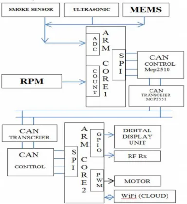
Block Diagram:
Fig. 1 Sensor based CAN bus Communication
First one known runs with ARM as master node and another as normal ARM data acquisition node to which sensors are
connected. Communications between two nodes are accomplished through High Speed CAN communication. Sensors connected are temperature, speed, and gas sensors. The master node collects all these information through CAN network and stores in three sessions. To acquire the results, respective session switches are provided at the master node. These results can be monitored on display.
II. Hardware Design
ARM core:
The ARM7 family includes the ARM7TDMI, ARM7TDMI-S, ARM720T & ARM7EJ-S processors. The ARM7TDMI core is
the industry’s most widely used 32-bit embedded RISC microprocessor solution. Optimized for cost and power-sensitive applications, the ARM7TDMI solution provides the low power consumption, small size, and high performance needed in portable, embedded applications. The ARM7TDMI-S core is the synthesizable version of the ARM7TDMI core, available in both VERILOG and VHDL, ready for compilation into processes supported by in-house or commercially available synthesis libraries. Optimized for flexibility and featuring an identical feature set to the hard macro cell, it improves time-to-market by reducing development time while allowing for increased design flexibility, and enabling >>98% fault coverage. The ARM720T hard macro cell contains the ARM7TDMI core, 8kb unified cache, and a Memory Management Unit (MMU) that allows the use of protected execution spaces and virtual memory. This macro cell is compatible with leading operating systems including Windows CE, Linux, palm OS, and SYMBIAN OS.
LPC 2148:
LPC2148 is a Microcontroller based Architecture. The ARM7TDMI-S is a general purpose 32-bit microprocessor, which offers high performance and very low power consumption. The ARM architecture is based on Reduced Instruction Set Computer (RISC) principles, and the instruction set and related decode mechanism are much simpler than those of micro programmed Complex Instruction Set Computers (CISC). This simplicity results in a high instruction throughput and impressive real-time interrupt response from a small and cost-effective processor core.
issue. The key idea behind Thumb is that of a super-reduced instruction set.
Essentially the ARM7TDMI-S processor has two instruction sets: The standard 32-bit ARM set, A 16-bit Thumb set.
The Thumb set’s 16-bit instruction length allows it to approach twice the density of standard ARM code while retaining most
of the ARM’s performance advantage over a traditional 16-bit processor using 16-bit registers. This is possible because Thumb code operates on the same 32-bit register set as ARM code. Thumb code is able to provide up to 65% of the code size of ARM, and 160% of the performance of an equivalent ARM processor connected to a 16-bit memory system.
Fig. 2 ARM7TDMI PCB board
CAN Bus:
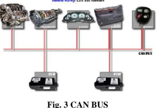
A controller area network (CAN bus) is a vehicle bus standard designed to allow microcontrollers and devices to communicate with each other in applications without a host computer. It is a message-based protocol, designed originally for automotive applications, but is also used in many other contexts.
Fig. 3 CAN BUS
CAN data transmission uses a lossless bit-wise arbitration method of contention resolution. This arbitration method requires all nodes on the CAN network to be synchronized to sample every bit on the CAN network at the same time. This is why some call CAN synchronous. Unfortunately the term synchronous is imprecise since the data is transmitted without a clock signal in an asynchronous format.
The CAN specifications use the terms "dominant" bits and "recessive" bits where dominant is a logical 0 (actively driven to a voltage by the transmitter) and recessive is a logical 1 (passively returned to a voltage by a resistor). The idle state is represented by the recessive level (Logical 1). If one node transmits a dominant bit and another node transmits a recessive bit then there is a collision and the dominant bit "wins". This means there is no delay to the higher priority message, and the node transmitting the lower priority message automatically attempts to re-transmit six bit clocks after the end of the dominant message. This makes CAN very suitable as a real time prioritized communications system.
The exact voltages for a logical 0 or 1 depend on the physical layer used, but the basic principle of CAN requires that each node listen to the data on the CAN network including the data that the transmitting node is transmitting. If a logical 1 is transmitted by all transmitting nodes at the same time, then a logical 1 is seen by all of the nodes, including both the transmitting node(s) and receiving node(s). If a logical 0 is transmitted by all transmitting node(s) at the same time, then a logical 0 is seen by all nodes. If a logical 0 is being transmitted by one or more nodes, and a logical 1 is being transmitted by one or more nodes, then a logical 0 is seen by all nodes including the node(s) transmitting the logical 1. When a node transmits a logical 1 but sees a logical 0, it realizes that there is a contention and it quits transmitting. By using this process, any node that transmits a logical 1 when another node transmits a logical 0 "drops out" or loses the arbitration. A node that loses arbitration requeues its message for later transmission and the CAN frame bit-stream continues without error until only one node is left transmitting. This means that the node that transmits the first 1 loses arbitration. Since the 11 (or 29 for CAN 2.0B) bit identifier is transmitted by all nodes at the start of the CAN frame, the node with the lowest identifier transmits more zero's at the start of the frame, and that is the node that wins the arbitration or has the highest priority.
WiFi Module:
A wireless access point (WAP) connects a group of wireless devices to an adjacent wired LAN. An access point resembles a network hub, relaying data between connected wireless devices in addition to a (usually) single connected wired device, most often an Ethernet hub or switch, allowing wireless devices to communicate with other wired devices.
Fig. 4 WiFi Module
Wireless adapters allow devices to connect to a wireless network. These adapters connect to devices using various external or internal interconnects such as PCI, miniPCI, USB, ExpressCard, Cardbus and PC Card. As of 2010, most newer laptop computers come equipped with built in internal adapters.
computer, as is the case with as Apple's AirPort, which is managed with the AirPort Utility on Mac OS X and iOS.
Wireless network bridges connect a wired network to a wireless network. A bridge differs from an access point: an access point connects wireless devices to a wired network at the data-link layer. Two wireless bridges may be used to connect two wired networks over a wireless link, useful in situations where a wired connection may be unavailable, such as between two separate homes.
Wireless range-extenders or wireless repeaters can extend the range of an existing wireless network. Strategically placed range-extenders can elongate a signal area or allow for the signal area to reach around barriers such as those pertaining in L-shaped corridors. Wireless devices connected through repeaters will suffer from an increased latency for each hop, as well as from a reduction in the maximum data throughput that is available. In addition, the effect of additional users using a network employing wireless range-extenders is to consume the available bandwidth faster than would be the case where but a single user migrates around a network employing extenders. For this reason, wireless range-extenders work best in networks supporting very low traffic throughput requirements, such as for cases where but a single user with a Wi-Fi equipped tablet migrates around the combined extended and non-extended portions of the total connected network. Additionally, a wireless device connected to any of the repeaters in the chain will have a data throughput that is also limited by the "weakest link" existing in the chain between where the connection originates and where the connection ends. Networks employing wireless extenders are also more prone to degradation from interference from neighboring access points that border portions of the extended network and that happen to occupy the same channel as the extended network.
LM35:
The LM35 series are precision integrated-circuit temperature sensors, whose output voltage is linearly proportional to the Celsius (Centigrade) temperature. The LM35 thus has an advantage over linear temperature sensors calibrated in ° Kelvin, as the user is not required to subtract a large constant voltage from its output to obtain convenient Centigrade scaling. The LM35 does not require any external calibration or trimming to provide typical accuracies of ±1⁄4°C
at room temperature and ±3⁄4°C over a full −55 to +150°C temperature range. Low cost is assured by trimming and
calibration at the wafer level. The LM35’s low output
impedance, linear output, and precise inherent calibration make interfacing to readout or control circuitry especially easy. It can be used with single power supplies, or with plus and minus
supplies. As it draws only 60 μA from its supply, it has very
low self-heating, less than 0.1°C in still air. The LM35 is rated to operate over a−55° to +150°C temperature range, while the
LM35C is rated for a −40° to +110°C range (−10° with
improved accuracy). The LM35 series is available packaged in hermetic TO-46 transistor packages, while the LM35C, LM35CA, and LM35D are also available in the plastic TO-92 transistor package. The LM35D is also available in an 8-lead surface mount small outline package and a plastic TO-220
package.
Features:
Calibrated directly in ° Celsius (Centigrade)
Linear + 10.0 mV/°C scale factor
0.5°C accuracy guarantee able (at +25°C)
Rated for full−55° to +150°C range
Suitable for remote applications
Low cost due to wafer-level trimming
Operates from 4 to 30 volts
Less than 60 μA current drain
Low self-heating, 0.08°C in still air
Nonlinearity only ±1⁄4°C typical
Low impedance output, 0.1ua for 1 mA load
Fig. 5 LM 35
The LM35 series are precision integrated-circuit temperature sensors, whose output voltage is linearly proportional to the Celsius (Centigrade) temperature. The LM35 thus has an advantage over linear temperature sensors calibrated in ° Kelvin, as the user is not required to subtract a large constant voltage from its output to obtain convenient Centigrade scaling. The LM35 does not require any external calibration or trimming to provide typical accuracies of ±¼°C at room temperature and ±¾°C over a full -55 to +150°C temperature range. Low cost is assured by trimming and calibration at the wafer level. The LM35's low output impedance, linear output, and precise inherent calibration make interfacing to readout or control circuitry especially easy. It can be used with single power supplies, or with plus and minus supplies. As it draws only 60 µA from its supply, it has very low self-heating, less than 0.1°C in still air. The LM35 is rated to operate over a -55° to +150°C temperature range, while the LM35C is rated for a -40° to +110°C range (-10° with improved accuracy). The LM35 series is available packaged in hermetic TO-46 transistor packages, while the LM35C, LM35CA, and LM35D are also available in the plastic TO-92 transistor package.
Driver Unit:
A relay is an electrically operated switch. Current flowing through the coil of the relay creates a magnetic field which attracts a lever and changes the switch contacts. The coil current can be on or off so relays have two switch positions and they are double throw (changeover) switches.
Relays allow one circuit to switch a second circuit which can be completely separate from the first. For example a low voltage battery circuit can use a relay to switch a 230V AC mains circuit. There is no electrical connection inside the relay between the two circuits the link is magnetic and mechanical. Relays are very simple devices. There are four major parts in every relay. They are
Armature that can be attracted by the electromagnet
Spring
Set of electrical contacts
Working:
When a current flows through the coil, the resulting magnetic field attracts an armature that is mechanically linked to a moving contact. The movement either makes or breaks a connection with a fixed contact. When the current to the coil is switched off, the armature is returned by a force approximately half as strong as the magnetic force to its relaxed position. Usually this is a spring, but gravity is also used commonly in industrial motor starters. Most relays are manufactured to operate quickly. In a low voltage application, this is to reduce noise. In a high voltage or high current application, this is to reduce arcing.
Fig. 6 Circuit symbol of a relay
The relay's switch connections are usually labeled COM, NC and NO:
COM = Common, always connect to this, it is the moving part of the switch.
NC = Normally Closed, COM is connected to this when the relay coil is off.
NO = Normally Open, COM is connected to this when the relay coil is on.
Alcohol Gas Sensor:
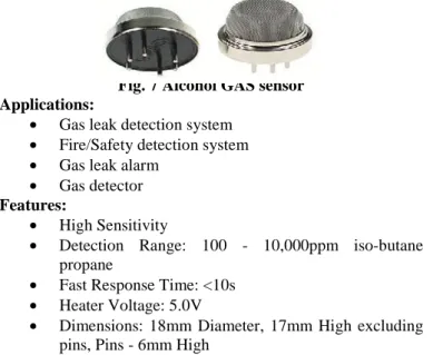
Ideal sensor for use to detect the presence of a dangerous LPG leak in your car or in a service station, storage tank environment. This unit can be easily incorporated into an alarm unit, to sound an alarm or give a visual indication of the LPG concentration. The sensor has excellent sensitivity combined with a quick response time. The sensor can also sense iso-butane, propane, LNG and cigarette smoke.
Fig. 7 Alcohol GAS sensor Applications:
Gas leak detection system
Fire/Safety detection system
Gas leak alarm
Gas detector
Features:
High Sensitivity
Detection Range: 100 - 10,000ppm iso-butane propane
Fast Response Time: <10s
Heater Voltage: 5.0V
Dimensions: 18mm Diameter, 17mm High excluding pins, Pins - 6mm High
Lcd Display:
Liquid crystal displays (LCDs) have materials which combine the properties of both liquids and crystals. Rather than having a melting point, they have a temperature range within which the molecules are almost as mobile as they would be in a liquid, but are grouped together in an ordered form similar to a crystal. An LCD consists of two glass panels, with the liquid crystal material sand witched in between them. The inner surface of the glass plates are coated with transparent electrodes which define the character, symbols or patterns to be displayed polymeric layers are present in between the electrodes and the liquid crystal, which makes the liquid crystal molecules to maintain a defined orientation angle. One each polarisers are pasted outside the two glass panels. These polarisers would rotate the light rays passing through them to a definite angle, in a particular direction. When the LCD is in the off state, light rays are rotated by the two polarisers and the liquid crystal, such that the light rays come out of the LCD without any orientation, and hence the LCD appears transparent. When sufficient voltage is applied to the electrodes, the liquid crystal molecules would be aligned in a specific direction. The light rays passing through the LCD would be rotated by the polarisers, which would result in
activating / highlighting the desired characters. The LCD’s are
lightweight with only a few millimeters thickness. Since the
LCD’s consume less power, they are compatible with low
power electronic circuits, and can be powered for long durations.
Fig. 8 LCD Display
Mems Sensor:
MEMS accelerometers are one of the simplest but also most applicable micro-electromechanical systems. They became indispensable in automobile industry, computer and audio-video technology. This seminar presents MEMS technology as a highly developing industry. Special attention is given to the capacitor accelerometers, how do they work and their applications. The seminar closes with quite extensively described MEMS fabrication.
An accelerometer is an electromechanical device that measures acceleration forces. These forces may be static, like the constant force of gravity pulling at our feet, or they could be dynamic - caused by moving or vibrating the accelerometer. There are many types of accelerometers developed and reported in the literature. The vast majority is based on piezoelectric crystals, but they are too big and too clumsy. People tried to develop something smaller, that could increase applicability and started searching in the field of
unique features and applications ranging from hard-disk protection on laptops to game controllers. More recently, the same sensor-core technology has become available in fully integrated, full-featured devices suitable for industrial applications. Micro machined accelerometers are a highly enabling technology with a huge commercial potential. They provide lower power, compact and robust sensing. Multiple sensors are often combined to provide multi-axis sensing and more accurate data
Mems Technology:
What could link an inkjet printer head, a video projector DLP system, a disposable bio-analysis chip and an airbag crash sensor - yes, they are all MEMS, but what is MEMS? Micro Electro Mechanical Systems or MEMS is a term coined around 1989 by Prof. R. Howe and others to describe an emerging research field, where mechanical
elements, like cantilevers or membranes had been manufactured at a scale more akin to microelectronics circuit than to lathe machining. It appears that these devices share the presence of features below 100m that are not machined using standard machining but using other techniques globally called micro-fabrication technology. Of course, this simple definition
would also include microelectronics, but there is a characteristic that electronic circuits do not share with MEMS.
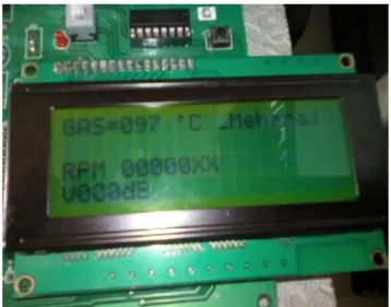
III. Result
The hardware circuit is as shown in the fig below. We have different sensors and their functionalities are also described below. We also have a module whose function is also described.
Fig. 9 Project Structure Smoke sensor:
Initially its value is 0 when it senses the gas it gives 1.
Fig. 10 Alcohol GAS sensor response
MEMs:
Initially its value is 0 when the object tilts it gives 1.
Fig. 11 MEMs sensor response Ultrasonic sensor:
Initially its value is 1 when it detects the object it controls the speed of the object i.e.0.
Fig. 12 Ultra Sonic Sensor Signal unit:
It will be at signals by using RF transceiver it will shows the zones so that we can be careful.
Signal unit Ultrasonic sensor
Mems Smoke
Fig. 13(a) Signal unit sensed SCHOOL ZONE
Conclusion
This project is implemented in two sections. First one known runs with ARM as master node and another as normal ARM data acquisition node to which sensors are connected. Communications between two nodes are accomplished through High Speed CAN communication. Sensors connected are temperature, speed, and Alcohol sensors. The master node collects all these information through CAN network and stores in three sessions. To acquire the results, respective session switches are provided at the master node. These results can be monitored on display.
References:
[1] Karl Henrik Johansson, Martin Törngren, and Lars Nielsen,
“Vehicle Application of Controller Area Network”.proc of The
Handbook of Networked and Embedded Control Systems Control Engineering, 2005, VI, pp.741-76
[2] Renjun Li, Chu Liu and Feng Luo, “A Design for
Automotive CAN Bus Monitoring System”, IEEE Vehicle
Power and Propulsion Conference (VPPC), September 3-5, 2008, Harbin,China
[3] CAN specification version 2.0. Robert Bosch GmbH, Stuttgart,Germany, 1991.
[4] Wilfried Voss, “A Comprehensible Guide to J1939”,
Published by Copperhill Technologies Corporation
[5] Steve Corrigan, “Introduction to the Controller Area Network”, Published by Texas Instruments Application
Report,SLOA101A,
August 2002–Revised July 2008
[6] O. González, M. Rodríguez, A. Ayala, J. Hernández and S.Rodríguez, “Application of PICs and microcontrollers in the measurement and control of parameters in industry”, Proc of
the International Journal of Electrical Engineering Education 41/3, pp.265-274, Feb 2001
[7] Microchip Technology Inc. DS41159E: PIC18FXX8 Data
Sheet Pat Richards, “A CAN physical layer discussion”,
Microchip Technology Inc. DS00228A
[8] Dogan Ibrahim, “Microcontroller based temperature monitoring and control”, ISBN: 0750655569, Elsevier Science
& Technology Books
[9] P.M. Knoll and B.B. Kosmowski, “Liquid crystal display
unit for reconfigurable instrument for automotive
applications”, Opto- Electronics Review, 10(1), 75 (2002) [10] MCP 2551 High speed CAN Transceiver Datasheet.
[11] National Semiconductor, “LM35 Precision Centigrade
Temperature Sensors Data sheet”, National Semiconductor
Corporation,