Abstract — Automatic multi-stored car parking system is very good substitute for car parking area in the era of miniaturization, where space has become a very big problem. It’s become a very crucial necessity to avoid the wastage of space in modern, big companies and apartments etc. For example, in a space where more than 100 cars need to be parked regularly, it’s a very difficult task to do so. This Automatic Car Parking allows any number of cars can be park according to requirement by enabling the parking of vehicles, floor after floor and thus reducing the space used. This makes the system modern and evens a space-saving one. This idea is developed using AVR ATMEGA 16 Microcontroller based on Zigbee Technology for Wireless Sensor Networks (WSN). WSN is seen as one of the most promising contemporary technologies for bridging the physical and virtual world thus, enabling them to interact. A WSN is composed of a number of sensor nodes, which are usually deployed in a region to observe particular phenomena in a geospatial domain. Sensor nodes are small stand alone embedded devices that are designed to perform specified simple computation and to send and receive data. They have attached them to a number of sensors, gathering data from the local environment that is being monitored.
Index Terms— Alfa Vizad RISC (AVR) Microcontroller, Institute of Electrical and Electronics Engineering (IEEE), ZigBee module, Wireless sensor networks (WSN), Wireless personal area Network (WPAN).
I. INTRODUCTION
With the rapid proliferation of vehicle availability and usage in recent years, finding a vacant car parking space is becoming more and more difficult, resulting in a number of practical conflicts. Parking problems are becoming ubiquitous and ever growing at an alarming rate in every major city. Wide usage of wireless technologies with the recent advances in wireless applications for parking, manifests that digital data dissemination could be the key to solve emerging parking problems. Wireless Sensor Network (WSN) technologies have attracted increased attention and are rapidly emerging due to their enormous application potential in diverse fields [4]. This field is expected to
Manuscript received September 15, 2012.
Mala Aggarwal, Electronics and Communication Engineering, B.B.S.B.E.C., Fatehgarh Sahib, Punjab, India.
Simmi Aggarwal, Computer Science, MDU Rohtak, Haryana, India.
R.S. Uppal, H.O.D., Computer Science,B.B.S.B.E.C., Fatehgarh Sahib, Punjab, India.
provide an efficient and cost-effective solution to the effluent car parking problems. This paper proposes a Smart Parking System based on wireless sensor network technology which provides advanced features like automated guidance. The paper describes the overall system architecture of our embedded system from hardware to software implementation in the view point of sensor networks. This paper also shows that the pre existing security surveillance (CCTVs) will be used as a sensing nodes to identify vacant parking space. The captured image will be processed through the AVR Microcontroller trial computer to store and update the occupancy status of available parking space vacancies in the database and the processed data will be transmitted via ZigBee to a central computer to store and update the occupancy status of available parking space vacancies in the database. The performance of this WSN based system can effectively satisfy the needs and requirements of existing parking hassles thereby minimizing the time consumed to find vacant parking lot, real time information rendering, and smart reservation mechanisms. ZigBee [1,2] defines the higher layer communication protocols built on the IEEE 802.15.4 standards for LR-PANs. ZigBee is a simple, low cost, and low power wireless communication technology used in embedded applications. ZigBee devices can form mesh networks connecting hundreds to thousands of devices together. ZigBee devices use very little power and can operate on a cell battery for many years. There are three types of ZigBee devices: Zig Bee coordinator, ZigBee router, and ZigBee end device. Zig-Bee coordinator initiates network formation, stores information, and can bridge networks together. ZigBee routers link groups of devices together and provide multi hop communication across devices. ZigBee end device consists of the sensors, actuators, and controllers that collects data and communicates only with the router or the coordinator. The ZigBee [3] standard is publicly available from June2005. 2.1.1 IEEE 802.15.4 Protocol.
II. IEEE802.15.4ZIGBEEPROTOCOL
The IEEE 802.15.4 is a part of the IEEE family of standards for the physical and link layers for Wireless Personal Area Networks (WPANs). The main focus of IEEE 802.15.4 is low data rate WPANs, with low complexity and low power consumption requirements. IEEE 802.15.4 uses device classification to reduce the complexity of the nodes. The standard classifies two types of devices to reduce complexity, a full function device (FFD) and a reduced function device
Zigbee Technology for Wireless Sensor
Networks (WSN) and application in automatic
car parking system
Volume 1, Issue 7, September 2012
(RFD). The RFD can only communicate with FFDs, but the FFD can communicate with both FFDs and RFDs. The IEEE 802.15.4 supports two Physical Layer (PHY) options. The 868/915MHz PHY known as low-band uses binary phase shift keying (BPSK) modulation whereas the 2.4 GHz PHY (high band) uses Offset Quadrature Phase Shift Keying (O-QPSK) modulation. The IEEE 802.15.4 standard also uses two types of channel access method depending upon network configuration. When non-beacon mode is enabled the network uses an un-slotted carrier sense multiple access with collision avoidance (CSMA-CA) channel access method. The beacon method uses an optional slotted CSMA-CA channel access method. The super frame structure is only used in beacon mode. In non beacon mode super frame structure is disabled and nodes compete for channel access via CSMA/CA. The super frame is divided into 16 slots, the first slot contains the transmitting beacon and the other 15 slots are used for node communication.
Coordinator node defines the structure of the super frame, with two sections: Connection Access Period (CAP) and Connection Free Period (CFP). The basic super frame structure is shown in figure 1. In a larger network, when the traffic volume is higher, most of the time slots are used for CAP, not for CFP [6]. Therefore this mode is not suitable for a network which involves a larger number of nodes.
Fig. 1: IEEE 802.15.4 Super frame Structure [7]
A non beacon network is more useable than the beacon enabled network. The Media Access Control (MAC) of the non-beacon mode is contention based CSMA/CA. Therefore typically most of the receiver nodes are continuously active. This requires a more robust power supply, but it allows for networks where nodes can receive and transmit data continuously. For larger networks like this vineyard monitoring system, the non beacon mode enabled network is more suitable. IEEE 802.15.4 networks can be separated into two main topologies, star and peer-to-peer.
Compared to the two topologies, the star topology has the most structured configuration. The Personal Area Network (PAN) coordinator node always sits in the centre of the network. All the other nodes need to communicate via the PAN coordinator node. The PAN Coordinator node relays messages to other nodes in the network. Direct intercommunication between other nodes is not allowed (figure 2).
Fig. 2: Star Network Topology
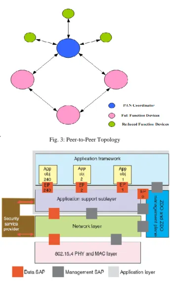
The peer-to-peer topology consists of three different types of nodes: PAN coordinator, full function node and reduced function nodes. In the peer-to-peer topology, an arbitrary array of connections can be created between full function devices and the PAN coordinator. Since a network layer is not defined in the standard, routing is not directly supported (refer to figure 1 and figure 3).
Fig. 3: Peer-to-Peer Topology
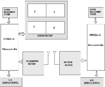
Fig. 4: ZigBee Stack Layer [9]
other devices. The ZigBee stack contains the networking layer, an application support sub-layer and a security service provider (SSP) [8].
III. IMPLEMENTATION OF CAR PARKING SYSTEM
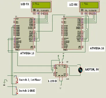
The implementation of automatic car parking system is shown in figure 5 which consists of the following parts.
Fig. 5: Automatic car parking system
ATMEGA-16 Microcontroller, LCD for Display system, Digital Sensors, Transmitter section, receiver section, Power supply management system. Power supply management system provides the 5V supply to the microcontroller. Digital sensor senses the cars and displays the corresponding floor information on the LCD display. Here are two LCD displays, one is for transmitter section and another is for receiver section. A display is provided at the ground floor which is basically a counter that displays number of cars in each floor. It informs whether the floors are fully filled with the cars or is it having place in a particular floor or not. There is facility of lift to carry the car to up and down. Movement of Lift is controlled by dc motor. In this project we have provided three floors of a building for car parking. Maximum storage capacity of each floor is given as ten. Storage capacity can be changed according to the requirement. When the lift reaches the first floor, the processor compares the filled amount to that of the already fed capacity of that floor, and if it finds that the first floor is fully filled, it goes to the second floor and thus the procedure stops here. As soon as a car is placed in a particular floor, the display counter at the ground floor increments as to indicate the floor capacity has decreased by one. After the lift places the car in a particular floor, it comes back to its normal position and that time, the motor that drives it, also stops.
IV. IMPLEMENTATION SCENARIOS
We have implemented the car parking for Ground floor to third floor. In the diagram the IR sensor is place by switch, 16 2 LCD display is used to display the information for Transmitter as well as Receiver. A lift mechanism is used in the implementation. If the status of Ground floor is full then lift moves towards first floor and returns to ground. Similarly if the first, second floors are full lift moves upward and returns to ground. A DC Motor is used for lift mechanism. ATMEGA 16 Microcontrollers works on the 5 V Power supply and dc motor works on 9 V. So, motor driver IC L 293 D is used to drive the motor and interfaced with ATMEGA 16 microcontroller.
Case1: Ground Floor car parking using one IR sensor, it can sense the status of Ground floor only it has the limitations to park the car on GND. If IR Sensor =1, Car parking is full and IR Sensor = 0 car parking has “VACANT SPACE”.
Fig. 6: Car parking for ground floor
Case 2: If the Ground floor is full, A lift mechanism is used to park the car on first floor which is implemented using motor as in the simulation diagram. If it rotates in clock wise direction means the lift is moving upward, if it rotates in anticlockwise direction, it means lift rotates in downward direction. Two IR sensors are used in this IR1 for ground floor and IR2 for First Floor.
Table I: Operation of First Floor Car Parking
IR1 IR2 Operation
0 0 VACANT SPACE
0 1 1 VACANT, 2 FULL 1 0 1 FULL, 2 VACANT
Volume 1, Issue 7, September 2012
Fig. 7: Car parking for first floor
Case 3: If the Ground floor is full, similar lift mechanism is used to park the car on first floor and second floor which is implemented using motor as in the simulation diagram. If it rotates in clock wise direction means the lift is moving upward, if it rotates in anticlockwise direction, it means lift rotates in downward direction. Three IR sensors are used in this IR1 for ground floor and IR2 for First Floor and IR3.
Fig. 8: Car parking for second floor
Table II: Operation of Second Floor Car Parking
IR1 IR2 IR3 Operation
0 0 0 VACANT SPACE
0 0 1 1 VACANT, 2 VACANT,3 FULL 0 1 0 1 VACANT, 2 FULL ,3 VACANT 0 1 1 1 VACANT, 2 FULL , 3 FULL 1 0 0 1 FULL, 2 VACANT, 3 VACANT 1 0 1 1 FULL, 2 VACANT, 3FULL 1 1 0 1 FULL, 2 FULL, 3 VACANT 1 1 1 ALL FULL
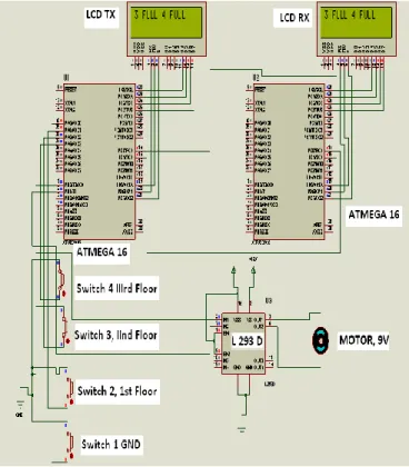
Case 4: If the Ground floor is full, similar lift mechanism is used to park the car on first floor an, second floor and third floor which is implemented using motor as in the simulation diagram. If it rotates in clock wise direction means the lift is moving upward, if it rotates in anticlockwise direction, it means lift rotates in downward direction. Three IR sensors are used in this IR1 for ground floor and IR2 for First Floor, IR 3 for second floor and IR4 for third floor.
Table III: Operation of Third Floor Car Parking
IR1 IR2 IR3 IR4 Operation
0 0 0 0 VACANT SPACE
0 0 0 1 1 VACANT, 2 VACANT,3
VACANT,4 FULL
0 0 1 0 1 VACANT, 2 VACANT ,3 FULL,4 VACANT
0 0 1 1 1 VACANT, 2 VACANT , 3 FULL,4 FULL
0 1 0 0 1 VACANT, 2 FULL, 3 VACANT,4 VACANT 0 1 0 1 1 VACANT, 2 FULL, 3
VACANT,4 FULL
0 1 1 0 1 VACANT , 2 FULL, 3 FULL,4 VACANT
0 1 1 1 1 VACANT , 2 FULL, 3 FULL,4 FULL
1 0 0 0 1 FULL,2 VACANT,3 VACANT,4 VACANT
1 0 0 1 1 FULL,2 VACANT,3 VACANT,4
1 0 1 0 1 FULL,2 FULL, VACANT,3,4 VACANT
1 0 1 1 1 FULL,2 VACANT,3 FULL,4 FULL
1 1 0 0 1 FULL,2 FULL,3 VACANT,4 VACANT
1 1 0 1 1 FULL,2 FULL,3 FULL, VACANT,4
1 1 1 0 1FULL, 2 FULL,3 FULL,4 VACANT
1 1 1 1 ALL FULL
Fig. 9: Car parking for third floor
V. SOFTWAREDEVELOPMENT
Microcontroller, when it is used to operate as a wireless network involves following steps [10]
Fig: 10 Steps for software development [10]
(1) Coding / Debugging- Coding or debugging is one in a high-level language (such as c or java). Compiler for a high-level language helps to reduce production time. To program the microcontrollers Win AVR [11] was used using C language. The source code has been commented to facilitate any occasional future improvement and maintenance. Win AVR is a suite of executable, open source software development tools for the Atmel AVR series of RISC microprocessors hosted on the Windows platform. It includes the GNU GCC compiler for C and C++. Win AVR contains all the tools for developing on the AVR. This includes AVR-gcc (compiler), AVR-gdb (debugger) etc.
(2) Compiling- After compiling the program, it is converted to machine level language in the form of o’s ans1’s.This file is called as the Hex file and is saved with the extension (.Hex). The compiler also generates errors in the program which should be removed for proper execution of the program.
(3) Burning- Burning the machine language (hex) file into the microcontroller’s program memory is achieved with a dedicated programmer, which attaches to a PC’s peripheral. PC’s serial port has been used for the purpose. For this purpose Ponyprog programmer was used to burn the machine language file into the microcontroller’s program memory. Ponyprog is serial device programmer software with a user-friendly GUI framework available for Windows95/98/ME/NT/2000/XP and Intel Linux. Its purpose is reading and writing every serial device. It supports I²C Bus, Micro wire, SPI EEPROM, and the Atmel AVR and Microchip PIC microcontroller. The microcontrollers were programmed in approximately two seconds with a high speed-programming mode. The program memory, which is of Flash type, has, just like the EEPROM, a limited lifespan. On AVR microcontroller family it may be reprogrammed up to a thousand times without any risk of data corruption Atmega16 Programmer (ISP) which is used to burn the program into AVR microcontrollers.
(4) Evaluation-If the system performs as desired by the user and performs all the tasks efficiently and effectively the software development phase is over and the project is ready to be installed in any of the industrial sites as a personal area network. If not, the entire process is repeated again to rectify the errors. One of the difficulties of programming microcontrollers is the limited amount of resources the programmer has to deal with. In PCs resources such as RAM and processing speed are basically limitless when compared to microcontrollers. In contrast to a PC, the code on microcontrollers should be as low on resources as possible, but being cost effective and power efficient makes it a better option. In the programming of the proposed system is used the following .c and .h file
(1) lcd.c -This c file contains the code for control of functionality of the attached LCD module. The code controls the initialization of the LCD, data writing on the LCD, and also the movement, characteristics and location of the cursor. It offers the facility to write data on the LCD character-by-character or string-wise. The command set used in the software is based on the command set used in the LCD based on Hitachi HD44780 ICs. This file contain InitLCD ( ),
LCDClear ( ), LCDWriteString ( ) and LCDWriteInit ( ).
Volume 1, Issue 7, September 2012
VI. CONCLUSION
Wireless car parking system implementation is really very challenging; we have implemented our system of car parking upto three floors. Zigbee transceiver module is used as wireless technology and the implementation of such system have following advantages:
Parking Space Monitoring: Monitoring Parking space from a remote location and controlling of pumps can be done. Better Utilization of space available: parking space better utilization efficiency saves time and more no of vehicles can be parked simultaneously.
Security Gates: Since through a specific access codes we could utilize the parking for a registered users. Deployment of a security barrier or tyre puncture strip if gate is breached. For over 25 years, Remote Control Technology has been a leader in innovative applications of wireless Radio Frequency (RF) remote control and telemetry devices. These Technologies is continually expanding its product offerings and services to meet emerging customer needs, and its implementation using wireless modules is the next future which will be implemented in malls, buildings and cities.
VII. REFERENCES
[1] ZigBee: Wireless control that simply works http://www.zigbee.org page (pp 1-15)
[2] Zig Bee Standards Overview, <http: // www. freescale.com/ web app /sps /site/ overview.jsp? nodeI d= 01J4Fs25657725. (pp 12-19, 65)
[3] Jennifer Yick, Biswanath Mukherjee, Dipak Ghosal (2009) Wireless sensor network survey * Department of Computer Science, University of California, Davis, CA95616, United State (pp 2,3,5)
[4] P. Vijay Kumar and Siddarth T.S, Asst. Prof. (Sr.G) ECE DEPARTMENT, SRM UNIVERSITY, Chennai, India, (2008) A PROTOTYPE PARKING SYSTEM USING WIRELESS SENSOR NETWORKSInternational Journal of Power Control Signal and Computation (IJPCSC) Vol. 1 No. 4 ISSN : 0976-268X (pp 1-10)
[5] A Thesis by T. A. S. Achala Perera (2011) ZigBee Wireless Soil Moisture Sensor Design for Vineyard Management System, A Thesis by T. A. S. Achala Perera
[6] Young Hun, S., et al. Performance evaluation of wireless networked control system using time-triggered IEEE 802.15.4. in ICCAS-SICE, 2009.
[7] Hyung Seok, K., S. Joo-Han, and L. Seok,(2007) Energy-Efficient Traffic Scheduling in IEEE 802.15.4 for Home Automation Networks. Consumer Electronics, IEEE Transactions on, 2007. 53(2): p. 369-374.
[8] Egan, D., April-May 2005 The emergence of ZigBee in building automation and industrial control. Computing & Control Engineering Journal, 16(2): p. 14-19.
[9] Garcia, R.R., 02/01/2006 Understanding the Zigbee stack. 02/01/2006(Freescale Semiconductor Inc.)
[10] Rajesh Singh, Akanksha, Shashank Mishra, Ankit Joshi / International Journal of Engineering Research and Applications (IJERA) ISSN: 2248-9622 www.ijera.com Vol. 2, Issue 3, May-Jun 2012, pp.133-138 WIRELESS PERSONAL AREA NETWORK NODE DESIGN AND SIMULATON OF ALCOHOL SENSOR USING ZIGBEE TRANSCEIVER MODULE.
[11] Singh, R.; Mishra, S. Year 2011 Temperature monitoring in wireless sensor network using Zigbee™ transceiver module‖ Year 2011 ICPCES – 2010 ISBN: 978-1-4244-8543-
[12 ]Young Wung Kim; Sang Jin Lee; Guk Hee Kim; Gi Joon Jeon; , Nov. 2009 "Wireless electronic nose network for real-time gas monitoring system," Robotic and Sensors Environments, 2009. ROSE 2009. IEEE International Workshop on , vol., no., pp.169-172, 6-7
[13] Zhao Xiaoqiang; Zhang Zuhou; , March 2010"Development of Remote Waste Gas Monitor System," Measuring Technology and Mechatronics Automation (ICMTMA), 2010 International Conference on, vol.1, no., pp.1105-1108, 13-14.
[14 ]Guo Xiu-cai; Zhao Jing; Zhang Xin-liang; , May 2010 ."The Research of Remote-Monitoring System of the Gas Based on Web," E-Business and E-Government (ICEE), 2010 International Conference on , vol., no., pp.2583-2586, 7-9
[15] Hua Fu; Tao Wang; Cui Yang; ,2009 "Gas monitoring system based on the multi-sensor information fusion," Electronic Measurement & Instruments, 2009. ICEMI' 09. 9th International Conference on , vol., no., pp.2-930-2-933, 16-19 Aug. 2009.
[16] CC2500 data sheet Single Chip Low Cost Low Power RF Transceiver 2008
[17] www, Wikipedia.com
[18] www. electrofriends.com
[19] www.datsheet.com
[20] Jae KyuSuhr · Ho Gi Jung · Kwang hyuk Bae Jaihie Kim (2010) “Automatic free parking space detection by using motion stereo-based 3D reconstruction”,: Machine Vision
and Applications 21:
[25] Pijush Kanti Babu,Kousik MandalJatindra Bimal Mukherjee, (2006)Coin Operated Automatic Car Parking System, A note on car parking. (pp 1,2, 6)
[26] Muhamad Ali maizidi book Edition 2nd, 2010, Microcontroller & Embedded system.
Mrs. Mala Aggarwal is currently pursuing M.Tech. in the stream of Electronics and Communication Engineering, in Baba Banda Singh Bahadur Engineering College in Fatehgarh Sahib, Punjab, India.
Mrs. Simmi Aggarwal is currently pursuing M.Tech. in the stream of Computer Science in Maharshi Dayanand University in Rohtak, Haryana, India.