Configuring IP
This chapter describes the Internet Protocol (IP) parameters on HP ProCurve routing switches and switches and how to configure them. After you add IP addresses and configure other IP parameters, see the following chapters for configuration information for the IP routing protocols:
• “Configuring RIP” on page 7-1 • “Configuring OSPF” on page 8-1 • “Configuring BGP4” on page 10-1
To configure and monitor IP, see the following sections:
• “Basic IP Parameters and Defaults – Routing Switches” on page 6-9 • “Basic IP Parameters and Defaults – HP 6208M-SX” on page 6-16 • “Configuring IP Parameters – Routing Switches” on page 6-18 • “Configuring IP Parameters – HP 6208M-SX” on page 6-73
• “Displaying IP Configuration Information and Statistics” on page 6-80
Basic Configuration
IP is enabled by default. Basic configuration consists of adding IP addresses and, for routing switches, enabling a route exchange protocol, such as Routing Information Protocol (RIP).
• If you are configuring a routing switch, see “Configuring IP Addresses” on page 6-18 to add IP addresses, then see one or more of the following to enable and configure the route exchange protocols:
• “Configuring RIP” on page 7-1 • “Configuring OSPF” on page 8-1 • “Configuring BGP4” on page 10-1
• If you are configuring a switch, see “Configuring the Management IP Address and Specifying the Default Gateway” on page 6-73 to add an IP address for management access through the network and to specify the default gateway.
The rest of this chapter describes IP and how to configure it in more detail. Use the information in this chapter if you need to change some of the IP parameters from their default values or you want to view configuration information or statistics.
Overview
The HP Procurve HP 6208M-SX switch and HP 9304M, HP 9308M, and HP 6308M-SX routing switches support Internet Protocol (IP) version 4. IP support on the HP 6208M-SX consists of basic services to support
management access and access to a default gateway. IP support on the routing switches includes all of the following, in addition to a highly configurable implementation of basic IP services including Address Resolution Protocol (ARP), ICMP Router Discovery Protocol (IRDP), and Reverse ARP (RARP):
• Route exchange protocols
• Routing Information Protocol (RIP) • Open Shortest Path First (OSPF)
• Border Gateway Protocol version 4 (BGP4) • Multicast protocols
• Internet Group Membership Protocol (IGMP) • Protocol Independent Multicast Dense (PIM-DM) • Protocol Independent Multicast Sparse (PIM-SM) • Distance Vector Multicast Routing Protocol (DVMRP) • Router redundancy protocols
• Virtual Router Redundancy Protocol Extended (VRRPE) • Virtual Router Redundancy Protocol (VRRP)
• Standby Router Protocol (SRP)
IP Interfaces
HP ProCurve devices allow you to configure IP addresses. On the routing switches, IP addresses are associated with individual interfaces. On the HP 6208M-SX, a single IP address serves as the management access address for the entire device.
All HP ProCurve devices support configuration and display of IP address in classical sub-net format (example: 192.168.1.1 255.255.255.0) and Classless Interdomain Routing (CIDR) format (example: 192.168.1.1/24). You can use either format when configuring IP address information. IP addresses are displayed in classical sub-net format by default but you can change the display format to CIDR. See “Changing the Network Mask Display to Prefix Format” on page 6-80.
Routing Switches
HP ProCurve routing switches allow you to configure IP addresses on the following types of interfaces: • Ethernet ports
• Virtual routing interfaces (used by VLANs to route among one another) • Loopback interfaces
Each IP address on a routing switch must be in a different sub-net. You can have only one interface that is in a given sub-net. For example, you can configure IP addresses 192.168.1.1/24 and 192.168.2.1/24 on the same routing switch, but you cannot configure 192.168.1.1/24 and 192.168.1.2/24 on the same routing switch. You can configure multiple IP addresses on the same interface.
The number of IP addresses you can configure on an individual interface depends on the routing switch model. To display the maximum number of IP addresses and other system parameters you can configure on a routing switch, see the “Configuring Basic Features” chapter of the Installation and Getting Started Guide.
You can use any of the IP addresses you configure on the routing switch for Telnet, Web management, or SNMP access.
The HP 6208M-SX Switch
You can configure an IP address on the HP 6208M-SX for management access to the switch. IP address is required for Telnet access, Web management access, and SNMP access.
You also can specify the default gateway for forwarding traffic to other sub-nets.
IP Packet Flow Through a Routing Switch
Figure 6.1 shows how an IP packet moves through an HP routing switch.
Figure 6.1 IP Packet flow through an HP routing switch
Figure 6.1 shows the following packet flow:
1. When the routing switch receives an IP packet, the routing switch checks for filters on the receiving interface.1 If a deny filter on the interface denies the packet, the routing switch discards the packet and performs no further processing, except generating a Syslog entry and SNMP message, if logging is enabled for the filter. 2. If the packet is not denied at the incoming interface, the routing switch looks in the session table for an entry
that has the same source IP address and TCP or UDP port as the packet. the session table contains a matching entry, the routing switch immediately forwards the packet, by addressing it to the destination IP
1.The filter can be an Access Control List (ACL) or an IP access policy. N
Y
Mult. Equal cost Paths
Outgoing Port
Load Balancing Algorithm
OSPF RIP
Static ARP Table Lowest Admin. Distance Y
N
Incoming
Port N
Y Fwding Cache Session
Table
PBR or IP acc policy
Lowest Metric N
Y
IP Route Table
ARP Cache
An
If
address and TCP or UDP port listed in the session table entry and sending the packet to a queue on the outgoing port(s) listed in the session table. The routing switch selects the queue based on the Quality of Service (QoS) level associated with the session table entry.
3. If the session table does not contain an entry that matches the packet’s source address and TCP or UDP port, the routing switch looks in the IP forwarding cache for an entry that matches the packet’s destination IP address. If the forwarding cache contains a matching entry, the routing switch forwards the packet to the IP address in the entry. The routing switch sends the packet to a queue on the outgoing port(s) listed in the forwarding cache. The routing switch selects the queue based on the Quality of Service (QoS) level associated with the forwarding cache entry.
4. If the IP forwarding cache does not have an entry for the packet, the routing switch checks the IP route table for a route to the packet’s destination. If the IP route table has a route, the routing switch makes an entry in the session table or the forwarding cache, and sends the route to a queue on the outgoing port(s).
• If the running-config contains a Policy-Based Routing (PBR) definition or an IP access policy for the packet, the software makes an entry in the session table. The routing switch uses the new session table entry to forward subsequent packets from the same source to the same destination.
• If the running-config does not contain a PBR definition or an IP access policy for the packet, the software creates a new entry in the forwarding cache. The routing switch uses the new cache entry to forward subsequent packets to the same destination.
The following sections describe the IP tables and caches: • ARP cache and static ARP table
• IP route table • IP forwarding cache • IP session table
The software enables you to display these tables. You also can change the capacity of the tables on an individual basis if needed by changing the memory allocation for the table.
ARP Cache and Static ARP Table
The ARP cache contains entries that map IP addresses to MAC addresses. Generally, the entries are for devices that are directly attached to the routing switch.
An exception is an ARP entry for an interface-based static IP route that goes to a destination that is one or more router hops away. For this type of entry, the MAC address is either the destination device’s MAC address or the MAC address of the router interface that answered an ARP request on behalf of the device, using proxy ARP. ARP Cache
The ARP cache can contain dynamic (learned) entries and static (user-configured) entries. The software places a dynamic entry in the ARP cache when the routing switch learns a device’s MAC address from an ARP request or ARP reply from the device.
The software can learn an entry when the switch or routing switch receives an ARP request from another IP forwarding device or an ARP reply. Here is an example of a dynamic entry:
IP Address MAC Address Type Age Port
1 207.95.6.102 0800.5afc.ea21 Dynamic 0 6
Each entry contains the destination device’s IP address and MAC address. Static ARP Table
In addition to the ARP cache, routing switches have a static ARP table. Entries in the static ARP table are user configured. You can add entries to the static ARP table regardless of whether the device the entry is for is connected to the routing switch.
NOTE: The routing switches have a static ARP table but the HP 6208M-SX does not.
Here is an example of a static ARP entry:
Index IP Address MAC Address Port
1 207.95.6.111 0800.093b.d210 1/1
Each entry lists the information you specified when you created the entry. To display ARP entries, see the following:
• “Displaying the ARP Cache” on page 6-85 – routing switch
• “Displaying the Static ARP Table” on page 6-87 – routing switch only • “Displaying ARP Entries” on page 6-101 – switch
To configure other ARP parameters, see the following:
• “Configuring ARP Parameters” on page 6-27 – routing switch only To increase the size of the ARP cache and static ARP table, see the following:
• For dynamic entries, see the “Configuring Basic Features” chapter of the Installation and Getting Started Guide. The ip-arp parameter controls the ARP cache size.
• Static entries, “Changing the Maximum Number of Entries the Static ARP Table Can Hold” on page 6-31 – routing switches only. The ip-static-arp parameter controls the static ARP table size.
IP Route Table
The IP route table contains paths to IP destinations.
NOTE: The HP 6208M-SX does not have an IP route table. The switch sends all packets addressed to another sub-net to the default gateway, which you specify when you configure the basic IP information on the switch. The IP route table can receive the paths from the following sources:
• A directly-connected destination, which means there are no router hops to the destination • A static IP route, which is a user-configured route
• A route learned through RIP • A route learned through OSPF • A route learned through BGP4
The IP route table contains the best path to a destination.
• When the software receives paths from more than one of the sources listed above, the software compares the administrative distance of each path and selects the path with the lowest administrative distance. The administrative distance is a protocol-independent value from 1 – 255.
• When the software receives two or more best paths from the same source and the paths have the same metric (cost), the software can load share traffic among the paths based on destination host or network address (based on the configuration).
Here is an example of an entry in the IP route table:
Destination NetMask Gateway Port Cost Type
1.1.0.0 255.255.0.0 99.1.1.2 1/1 2 R
Each IP route table entry contains the destination’s IP address and sub-net mask and the IP address of the next hop router interface to the destination. Each entry also indicates the port attached to the destination or the next hop to the destination, the route’s IP metric (cost), and the type. The type indicates how the IP route table received the route.
To display the IP route table, see the following:
• “Displaying the IP Route Table” on page 6-90 – routing switch only To configure a static IP route, see the following:
• “Configuring Static Routes” on page 6-36 – routing switch only To clear a route from the IP route table, see the following:
• “Clearing IP Routes” on page 6-93 – routing switch only
To increase the size of the IP route table for learned and static routes, see the “Configuring Basic Features” chapter of the Installation and Getting Started Guide:
• For learned routes, modify the ip-route parameter. • For static routes, modify the ip-static-route parameter. IP Forwarding Cache
The IP forwarding cache provides a fast-path mechanism for forwarding IP packets. The cache contains entries for IP destinations. When an HP ProCurve routing switch has completed processing and addressing for a packet and is ready to forward the packet, the device checks the IP forwarding cache for an entry to the packet’s destination.
• If the cache contains an entry with the destination IP address, the device uses the information in the entry to forward the packet out the ports listed in the entry. The destination IP address is the address of the packet’s final destination. The port numbers are the ports through which the destination can be reached.
• If the cache does not contain an entry and the traffic does not qualify for an entry in the session table instead, the software can create an entry in the forwarding cache.
Each entry in the IP forwarding cache has an age timer. If the entry remains unused for ten minutes, the software removes the entry. The age timer is not configurable.
NOTE: The HP 6208M-SX does not have an IP forwarding cache. Here is an example of an entry in the IP forwarding cache:
IP Address Next Hop MAC Type Port Vlan Pri
1 192.168.1.11 DIRECT 0000.0000.0000 PU n/a 0
Each IP forwarding cache entry contains the IP address of the destination, and the IP address and MAC address of the next-hop router interface to the destination. If the destination is actually an interface configured on the routing switch itself, as shown here, then next-hop information indicates this. The port through which the destination is reached is also listed, as well as the VLAN and Layer 4 QoS priority associated with the destination if applicable.
To display the IP forwarding cache, see “Displaying the Forwarding Cache” on page 6-88.
NOTE: You cannot add static entries to the IP forwarding cache, although chassis routing switches do have options to optimize the cache and increase the number of entries the cache can contain. See “Optimizing the IP Forwarding Cache” on page 6-60 and the “Configuring Basic Features” chapter of the Installation and Getting Started Guide.
To increase the size of the IP forwarding cache, see the “Configuring Basic Features” chapter of the Installation and Getting Started Guide. The ip-cache parameter controls the size of the IP forwarding cache.
Layer 4 Session Table
The Layer 4 session provides a fast path for forwarding packets. A session is an entry that contains complete Layer 3 and Layer 4 information for a flow of traffic. Layer 3 information includes the source and destination IP addresses. Layer 4 information includes the source and destination TCP and UDP ports. For comparison, the IP forwarding cache contains the Layer 3 destination address but does not contain the other source and destination address information of a Layer 4 session table entry.
The switch or routing switch selects the session table instead of the IP forwarding table for fast-path forwarding for the following features:
• Policy-Based Routing (PBR)
• Layer 4 Quality-of-Service (QoS) policies • IP access policies
To increase the size of the session table, see the “Configuring Basic Features” chapter of the Installation and Getting Started Guide. The ip-qos-session parameter controls the size of the session table.
IP Route Exchange Protocols
HP ProCurve routing switches support the following IP route exchange protocols: • Routing Information Protocol (RIP)
• Open Shortest Path First (OSPF)
• Border Gateway Protocol version 4 (BGP4)
All these protocols provide routes to the IP route table. You can use one or more of these protocols, in any combination. The protocols are disabled by default. For configuration information, see the following: • “Configuring RIP” on page 7-1
• “Configuring OSPF” on page 8-1 • “Configuring BGP4” on page 10-1
IP Multicast Protocols
HP ProCurve routing switches also support the following Internet Group Membership Protocol (IGMP) based IP multicast protocols:
• Protocol Independent Multicast – Dense mode (PIM-DM) • Protocol Independent Multicast – Sparse mode (PIM-SM) • Distance Vector Multicast Routing Protocol (DVMRP)
For configuration information, see “Configuring IP Multicast Protocols” on page 9-1.
NOTE: The HP 6208M-SX supports IGMP and can forward IP multicast packets. See the “Configuring Basic Features” chapter of the Installation and Getting Started Guide.
IP Interface Redundancy Protocols
You can configure an HP ProCurve routing switch to back up an IP interface configured on another HP ProCurve routing switch. If the link for the backed up interface becomes unavailable, the other routing switch can continue service for the interface. This feature is especially useful for providing a backup to a network’s default gateway. HP ProCurve routing switches support the following IP interface redundancy protocols:
• Virtual Router Redundancy Protocol (VRRP) – A standard router redundancy protocol based on RFC 2338. You can use VRRP to configure HP routing switches and third-party routers to back up IP interfaces on other HP routing switches or third-party routers.
• Virtual Router Redundancy Protocol Extended (VRRPE) – An HP extension to standard VRRP that adds additional features and overcomes limitations in standard VRRP. You can use VRRPE only on HP routing switches.
• Standby Router Protocol (SRP) – An HP router redundancy protocol developed before VRRP and VRRPE that provides some of the features of VRRP and some of the features of VRRPE. You can use SRP only on the HP 9304M, HP 9308M, and HP 6308M-SX routing switches.
For configuration information, see the following:
• Virtual Router Redundancy Protocol Extended (VRRPE) – see “Configuring VRRP and VRRPE” on page 12-1.
• Virtual Router Redundancy Protocol (VRRP) – see “Configuring VRRP and VRRPE” on page 12-1. • Standby Router Protocol (SRP) – see “Configuring SRP” on page 13-1
Network Address Translation
HP’s chassis routing switches support Network Address Translation (NAT). NAT enables private IP networks that use nonregistered IP addresses to connect to the Internet. Configure NAT on an HP routing switch that is placed at the border of an inside network and an outside network (such as the Internet). NAT translates the internal local addresses to globally unique IP addresses before sending packets to the outside network.
For configuration information, see “Network Address Translation” on page 11-1.
Access Control Lists and IP Access Policies
HP routing switches provide two mechanisms for filtering IP traffic: • Access Control Lists (ACLs)
• IP access policies
Both methods allow you to filter packets based on Layer 3 and Layer 4 source and destination information. ACLs also provide great flexibility by providing the input to various other filtering mechanisms such as route maps, which are used by BGP4. ACLs also provide the input for Policy-Based Routing (PBR), which allows you to selectively modify and route IP packets based on their source IP address.
IP access policies allow you to configure QoS based on sessions (Layer 4 traffic flows).
Only one of these filtering mechanisms can be enabled on an HP device at a time. HP devices can store forwarding information for both methods of filtering in the session table.
For configuration information, see the following: • “Using Access Control Lists (ACLs)” on page 3-1 • “Policies and Filters” on page C-1
Basic IP Parameters and Defaults – Routing Switches
IP is enabled by default. The following IP-based protocols are all disabled by default: • Route exchange protocols• Routing Information Protocol (RIP) – see “Configuring RIP” on page 7-1 • Open Shortest Path First (OSPF) – see “Configuring OSPF” on page 8-1
• Border Gateway Protocol version 4 (BGP4) – see “Configuring BGP4” on page 10-1 • Multicast protocols
• Internet Group Membership Protocol (IGMP) – see “Changing Global IP Multicast Parameters” on page 9-2
• Protocol Independent Multicast Dense (PIM-DM) – see “PIM Dense Overview” on page 9-4 • Protocol Independent Multicast Sparse (PIM-SM) – see “PIM Sparse Overview” on page 9-12 • Distance Vector Multicast Routing Protocol (DVMRP) – see “DVMRP Overview” on page 9-39 • Router redundancy protocols
• Virtual Router Redundancy Protocol Extended (VRRPE) – see “Configuring VRRP and VRRPE” on page 12-1.
• Virtual Router Redundancy Protocol (VRRP) – see “Configuring VRRP and VRRPE” on page 12-1. • Standby Router Protocol (SRP) – see “Configuring SRP” on page 13-1
The following tables list the routing switch IP parameters, their default values, and where to find configuration information.
NOTE: For information about parameters in other protocols based on IP, such as RIP, OSPF, and so on, see the configuration chapters for those protocols.
When Parameter Changes Take Effect
Most IP parameters described in this chapter are dynamic. They take effect immediately, as soon as you enter the CLI command or select the Web management interface option. You can verify that a dynamic change has taken effect by displaying the running-config. To display the running-config, enter the show running-config or write terminal command at any CLI prompt. (You cannot display the running-config from the Web management interface.)
To save a configuration change permanently so that the change remains in effect following a system reset or software reload, save the change to the startup-config file.
• To save configuration changes to the startup-config file, enter the write memory command from the Privileged EXEC level of any configuration level of the CLI.
• To save the configuration changes using the Web management interface, select the Save link at the bottom of the dialog. Select Yes when prompted to save the configuration change to the startup-config file on the device’s flash memory. You also can access the dialog for saving configuration changes by clicking on Command in the tree view, then clicking on Save to Flash.
Changes to memory allocation require you to reload the software after you save the changes to the startup-config file. When reloading the software is required to complete a configuration change described in this chapter, the procedure that describes the configuration change includes a step for reloading the software.
IP Global Parameters – Routing Switches
Table 6.1 lists the IP global parameters for routing switches.
Table 6.1: IP Global Parameters – routing switches
Parameter Description Default See page...
IP state The Internet Protocol, version 4 Enabled
Note: ou cannot disable IP.
n/a
IP address and mask notation
Format for displaying an IP address and its network mask information. You can enable one of the following:
• Class-based format; example: 192.168.1.1 255.255.255.0
• Classless Interdomain Routing (CIDR) format; example: 192.168.1.1/24
Class-based
Note: hanging this parameter affects the display of IP
addresses, but you can enter addresses in either format
regardless of the display setting.
6-80
Router ID The value that routers use to identify themselves to other routers when exchanging route information. OSPF and BGP4 use router IDs to identify routers. RIP does not use the router ID.
The lowest-numbered IP address configured on the lowest
numbered virtual routing interface (VE). If no VE is configured, then the lowest numbered IP address configured on the device.
6-24
Address Resolution Protocol (ARP)
A standard IP mechanism that routers use to learn the Media Access Control (MAC) address of a device on the network. The router sends the IP address of a device in the ARP request and receives the device’s MAC address in an ARP reply.
Enabled 6-27
ARP age The amount of time the device keeps a MAC address learned through ARP in the device’s ARP cache. The device resets the timer to zero each time the ARP entry is refreshed and removes the entry if the timer reaches the ARP age.
Ten minutes 6-28
Proxy ARP An IP mechanism a router can use to answer an ARP request on behalf of a host, by replying with the router’s own MAC address instead of the host’s.
Disabled 6-29
Static ARP entries
An ARP entry you place in the static ARP table. Static entries do not age out.
No entries 6-29
Time to Live (TTL)
The maximum number of routers (hops) through which a packet can pass before being discarded. Each router decreases a packet’s TTL by 1 before forwarding the packet. If decreasing the TTL causes the TTL to be 0, the router drops the packet instead of forwarding it.
64 hops 6-32
Y
Table 6.1: IP Global Parameters – routing switches (Continued)
Directed broadcast forwarding
A directed broadcast is a packet containing all ones (or in some cases, all zeros) in the host portion of the destination IP address. When a router forwards such a broadcast, it sends a copy of the packet out each of its enabled IP interfaces.
Note: You also can enable or disable this parameter on an individual interface basis. See Table 6.2 on page 6-14.
Disabled 6-32
Directed broadcast mode
The packet format the router treats as a directed broadcast. The following formats can be directed broadcast:
• All ones in the host portion of the packet’s destination address.
• All zeroes in the host portion of the packet’s destination address.
All ones
Note: f you enable all-zeroes directed broadcasts, all-ones directed broadcasts remain enabled. 6-34 Source-routed packet forwarding
A source-routed packet contains a list of IP addresses through which the packet must pass to reach its destination.
Enabled 6-33
ICMP Router Discovery Protocol (IRDP)
An IP protocol a router can use to advertise the IP addresses of its router interfaces to directly attached hosts. You can enable or disable the protocol, and change the following protocol parameters: • Forwarding method (broadcast or multicast) • Hold time
• Maximum advertisement interval • Minimum advertisement interval • Router preference level
Note: You also can enable or disable IRDP and configure the parameters on an individual interface basis. e Table 6.2 on page 6-14.
Disabled 6-62
Reverse ARP (RARP)
A IP mechanism a host can use to request an IP address from a directly attached router when the host boots.
Enabled 6-64
Static RARP entries
An IP address you place in the RARP table for RARP requests from hosts.
Note: You must enter the RARP entries manually. The routing switch does not have a mechanism for learning or dynamically generating RARP entries.
No entries 6-66
Maximum BootP relay hops
The maximum number of hops away a BootP server can be located from a router and still be used by the router’s clients for network booting.
Four 6-72
Parameter Description Default See page...
I
Table 6.1: IP Global Parameters – routing switches (Continued)
Domain name for Domain Name Server (DNS) resolver
A domain name (example: amaynes.router.com) you can use in place of an IP address for certain
operations such as IP pings, trace routes, and Telnet management connections to the router.
None configured 6-21
DNS default gateway addresses
A list of gateways attached to the router through which clients attached to the router can reach DNSs.
None configured 6-21
IP unicast cache performance mode
The amount of available IP cache that is set aside for IP unicast entries. When the router caches unicast forwarding entries, the cached entries provide an optimal path through the router because the router CPU does not need to process the packets for forwarding. nce a packet is processed, the forwarding information is placed in the cache for reuse.
Chassis devices provide an optional high performance mode for allocating additional cache space for unicast forwarding entries. Use this option when the router is handling a very large number of unicast flows (source plus destination pairs) and you want to ensure that more flows can remain in the cache at one time.
Standard 6-60
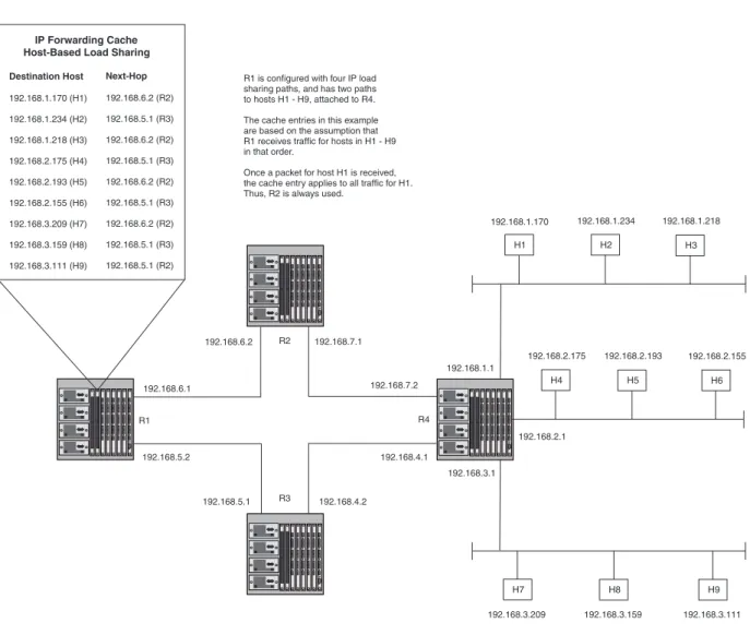
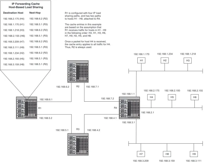
IP load sharing A feature that enables the router to balance traffic to a specific destination across multiple equal-cost paths. Load sharing uses a simple round-robin mechanism and is based on destination address.
Note: Load sharing is sometimes called Equal Cost Multi Path (ECMP).
Enabled 6-48
IP load sharing aggregation
A feature on Chassis devices that increases the capacity of the load sharing cache by aggregating destination addresses into networks. When IP load sharing aggregation is enabled, each cache entry is an aggregate network for multiple destination hosts. If IP load sharing aggregation not enabled, the device creates a separate load sharing cache entry for each destination host address.
Note: Load sharing aggregation is not available on Fixed-port devices. xed-port devices cache load sharing entries based on destination host addresses.
On Chassis devices, aggregated by network On Fixed-port devices, single host entries
6-58
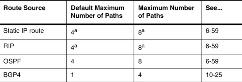
Maximum IP load sharing paths
The maximum number of equal-cost paths across which the router is allowed to distribute traffic.
Four 6-59
Parameter Description Default See page...
O
Table 6.1: IP Global Parameters – routing switches (Continued)
Origination of default routes
You can enable a router to originate default routes for the following route exchange protocols, on an individual protocol basis:
• RIP • OSPF • BGP4
Disabled 7-10 8-32 10-29
Default route aggregation
Optimizes forwarding cache space by aggregating cache entries for destinations to which the router forwards traffic using a default route. When you enable default route aggregation, the router makes a single cache entry for a destination network instead of multiple entries for the hosts on the network.
Separate cache entry for each destination host
6-61
Default network route
The router uses the default network route if the IP route table does not contain a route to the destination and also does not contain an explicit default route (0.0.0.0 0.0.0.0 or 0.0.0.0/0).
None configured 6-46
Static route An IP route you place in the IP route table. No entries 6-36 Source interface The IP address the router uses as the source address
for Telnet, RADIUS, or TACACS/TACACS+ packets originated by the router. The router can select the source address based on either of the following: • The lowest-numbered IP address on the
interface the packet is sent on.
• The lowest-numbered IP address on a specific interface. The address is used as the source for all packets of the specified type regardless of interface the packet is sent on.
The lowest-numbered IP address on the interface the packet is sent on.
6-25
IP Interface Parameters – Routing Switches
Table 6.2 lists the interface-level IP parameters for routing switches.
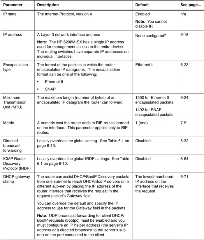
Table 6.2: IP Interface Parameters – routing switches
Parameter Description Default See page...
IP state The Internet Protocol, version 4 Enabled
Note: ou cannot disable IP.
n/a
IP address A Layer 3 network interface address
Note: The HP 6208M-SX has a single IP address used for management access to the entire device. The routing switches have separate IP addresses on individual interfaces.
None configureda 6-18
Encapsulation type
The format of the packets in which the router encapsulates IP datagrams. The encapsulation format can be one of the following:
• Ethernet II • SNAP
Ethernet II 6-23
Maximum Transmission Unit (MTU)
The maximum length (number of bytes) of an encapsulated IP datagram the router can forward.
1500 for Ethernet II encapsulated packets 1492 for SNAP encapsulated packets
6-24
Metric A numeric cost the router adds to RIP routes learned on the interface. This parameter applies only to RIP routes.
1 (one) 7-5
Directed broadcast forwarding
Locally overrides the global setting. See Table 6.1 on page 6-10.
Disabled 6-32
ICMP Router Discovery Protocol (IRDP)
Locally overrides the global IRDP settings. See Table 6.1 on page 6-10.
Disabled 6-64
DHCP gateway stamp
The router can assist DHCP/BootP Discovery packets from one sub-net to reach DHCP/BootP servers on a different sub-net by placing the IP address of the router interface that receives the request in the request packet’s Gateway field.
You can override the default and specify the IP address to use for the Gateway field in the packets.
Note: UDP broadcast forwarding for client DHCP/ BootP requests (bootpc) must be enabled and you must configure an IP helper address (the server’s IP address or a directed broadcast to the server’s sub net) on the port connected to the client.
The lowest-numbered IP address on the interface that receives the request
6-71 Y
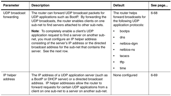
Table 6.2: IP Interface Parameters – routing switches (Continued)
UDP broadcast forwarding
The router can forward UDP broadcast packets for UDP applications such as BootP. By forwarding the UDP broadcasts, the router enables clients on one sub-net to find servers attached to other sub-nets.
Note: To completely enable a client’s UDP application request to find a server on another sub net, you must configure an IP helper address consisting of the server’s IP address or the directed broadcast address for the sub-net that contains the server. e the next row.
The router helps forward broadcasts for the following UDP application protocols: • bootps
• dns
• netbios-dgm • netbios-ns • tacacs • tftp • time
6-68
IP helper address
The IP address of a UDP application server (such as a BootP or DHCP server) or a directed broadcast address. IP helper addresses allow the router to forward requests for certain UDP applications from a client on one sub-net to a server on another sub-net.
None configured 6-69
Parameter Description Default See page...
Se
a.Some devices have a factory default, such as 209.157.22.154, used for troubleshooting during installation. For routing switches, the address is on port 1 (or 1/1).
Basic IP Parameters and Defaults – HP 6208M-SX
IP is enabled by default. The following tables list the switch IP parameters, their default values, and where to find configuration information.
NOTE: The HP 6208M-SX also provides IP multicast forwarding, which is enabled by default. For information about this feature, see the “Configuring Basic Features” chapter of the Installation and Getting Started Guide.
IP Global Parameters – HP 6208M-SX
Table 6.3 lists the IP global parameters for the switch.
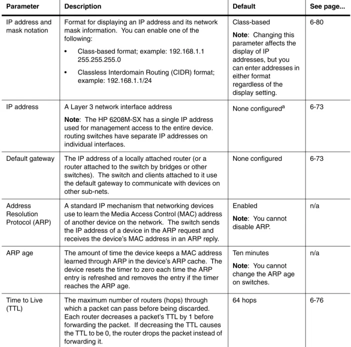
Table 6.3: IP Global Parameters – switch
Parameter Description Default See page...
IP address and mask notation
Format for displaying an IP address and its network mask information. You can enable one of the following:
• Class-based format; example: 192.168.1.1 255.255.255.0
• Classless Interdomain Routing (CIDR) format; example: 192.168.1.1/24
Class-based
Note: hanging this parameter affects the display of IP
addresses, but you can enter addresses in either format
regardless of the display setting.
6-80
IP address A Layer 3 network interface address
Note: The HP 6208M-SX has a single IP address used for management access to the entire device. routing switches have separate IP addresses on individual interfaces.
None configureda 6-73
Default gateway The IP address of a locally attached router (or a router attached to the switch by bridges or other switches). The switch and clients attached to it use the default gateway to communicate with devices on other sub-nets.
None configured 6-73
Address Resolution Protocol (ARP)
A standard IP mechanism that networking devices use to learn the Media Access Control (MAC) address of another device on the network. The switch sends the IP address of a device in the ARP request and receives the device’s MAC address in an ARP reply.
Enabled
Note: ou cannot disable ARP.
n/a
ARP age The amount of time the device keeps a MAC address learned through ARP in the device’s ARP cache. The device resets the timer to zero each time the ARP entry is refreshed and removes the entry if the timer reaches the ARP age.
Ten minutes
Note: ou cannot change the ARP age on switches.
n/a
Time to Live (TTL)
The maximum number of routers (hops) through which a packet can pass before being discarded. Each router decreases a packet’s TTL by 1 before forwarding the packet. If decreasing the TTL causes the TTL to be 0, the router drops the packet instead of forwarding it.
64 hops 6-76
C
Y
Table 6.3: IP Global Parameters – switch (Continued)
Domain name for Domain Name Server (DNS) resolver
A domain name (example: amaynes.router.com) you can use in place of an IP address for certain
operations such as IP pings, trace routes, and Telnet management connections to the router.
None configured 6-74
DNS default gateway addresses
A list of gateways attached to the router through which clients attached to the router can reach DNSs.
None configured 6-74
Source interface The IP address the switch uses as the source address for Telnet, RADIUS, or TACACS/TACACS+ packets originated by the router. e switch uses its management IP address as the source address for these packets.
The management IP address of the switch.
Note: his parameter is not configurable on the HP 6208M-SX.
n/a
DHCP gateway stamp
The device can assist DHCP/BootP Discovery packets from one sub-net to reach DHCP/BootP servers on a different sub-net by placing the IP address of the router interface that forwards the packet in the packet’s Gateway field.
You can specify up to 32 gateway lists. A gateway list contains up to eight gateway IP addresses. You activate DHCP assistance by associating a gateway list with a port.
When you configure multiple IP addresses in a gateway list, the switch inserts the addresses into the DHCP Discovery packets in a round robin fashion.
None configured 6-79
Parameter Description Default See page...
Th
T
a.Some devices have a factory default, such as 209.157.22.154, used for troubleshooting during installation. For routing switches, the address is on port 1 (or 1/1).
Interface IP Parameters – HP 6208M-SX
Table 6.4 lists the interface-level IP parameters for the HP 6208M-SX.
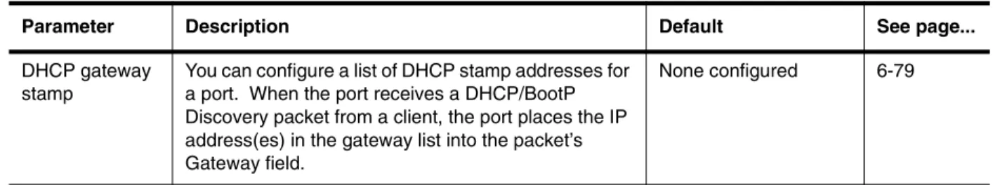
Table 6.4: Interface IP Parameters – switch
Parameter Description Default See page...
DHCP gateway stamp
You can configure a list of DHCP stamp addresses for a port. When the port receives a DHCP/BootP Discovery packet from a client, the port places the IP address(es) in the gateway list into the packet’s Gateway field.
Configuring IP Parameters – Routing Switches
The following sections describe how to configure IP parameters. Some parameters can be configured globally while others can be configured on individual interfaces. Some parameters can be configured globally and overridden for individual interfaces.
NOTE: This section describes how to configure IP parameters for routing switches. For IP configuration information for the HP 6208M-SX, see “Configuring IP Parameters – HP 6208M-SX” on page 6-73.
Configuring IP Addresses
You can configure an IP address on the following types of routing switch interfaces: • Ethernet port
• Virtual routing interface (also called a Virtual Ethernet or “VE”) • Loopback interface
By default, you can configure up to 24 IP addresses on each interface. On the HP 6308M-SX, you can increase this amount to up to 64 IP sub-net addresses per port by increasing the size of the subnet-per-interface table. See the “Configuring Basic Features” chapter of the Installation and Getting Started Guide.
HP ProCurve devices support both classical IP network masks (Class A, B, and C sub-net masks, and so on) and Classless Interdomain Routing (CIDR) network prefix masks.
• To enter a classical network mask, enter the mask in IP address format. For example, enter “209.157.22.99 255.255.255.0” for an IP address with a Class-C sub-net mask.
• To enter a prefix network mask, enter a forward slash ( / ) and the number of bits in the mask immediately after the IP address. For example, enter “209.157.22.99/24” for an IP address that has a network mask with 24 significant bits (ones).
By default, the CLI displays network masks in classical IP address format (example: 255.255.255.0). You can change the display to prefix format. See “Changing the Network Mask Display to Prefix Format” on page 6-80. Assigning an IP Address to an Ethernet Port
To assign an IP address to an Ethernet port, use either of the following methods.
USING THE CLI
To assign an IP address to port 1/1, enter the following commands: HP9300(config)# interface ethernet 1/1
HP9300(config-if-1/1)# ip address 192.45.6.1 255.255.255.0
Syntax: ip address <ip-addr> <ip-mask> [secondary] or
Syntax: ip address <ip-addr>/<mask-bits> [secondary]
Use the secondary parameter if you have already configured an IP address within the same sub-net on the interface.
NOTE: You also can enter the IP address and mask in CIDR format, as follows: HP9300(config-if-1/1)# ip address 192.45.6.1/24
USING THE WEB MANAGEMENT INTERFACE
To assign an IP address and mask to a router interface:
1. Log on to the device using a valid user name and password for read-write access. The System configuration dialog is displayed.
2. Select the IP Address link. The IP addresses already configured on the device are listed in a table. Select Add IP Address to display the following panel.
3. Select the port (and slot if applicable) on which you want to configure the address.
NOTE: This example shows the panel for configuring an address on a routing switch. On the HP 6208M-SX, the IP address is global and applies to all the switch’s ports. Thus, you do not need to select a port. 4. Enter the IP address and network mask.
5. If the port already has an IP address configured, select the Secondary checkbox. 6. Click the Add button to save the change to the device’s running-config file.
7. Select the Save link at the bottom of the dialog. Select Yes when prompted to save the configuration change to the startup-config file on the device’s flash memory.
NOTE: You also can access the dialog for saving configuration changes by clicking on Command in the tree view, then clicking on Save to Flash.
Assigning an IP Address to a Loopback Interface
Loopback interfaces are always up, regardless of the states of physical interfaces. They can add stability to the network because they are not subject to route flap problems that can occur due to unstable links between a routing switch and other devices. You can configure up to eight loopback interfaces on a routing switch. You can add up to 24 IP addresses to each loopback interface.
NOTE: If you configure the HP routing switch to use a loopback interface to communicate with a BGP4 neighbor, you also must configure a loopback interface on the neighbor and configure the neighbor to use that loopback interface to communicate with the HP routing switch. See “Adding a Loopback Interface” on page 10-13. To add a loopback interface, use one of the following methods.
USING THE CLI
To add a loopback interface, enter commands such as those shown in the following example: HP9300(config-bgp-router)# exit
HP9300(config-lbif-1)# ip address 10.0.0.1/24
Syntax: interface loopback <num> The <num> value can be from 1 – 8.
Syntax: [no] ip address <ip-addr> <ip-mask> [secondary] or
Syntax: [no] ip address <ip-addr>/<mask-bits> [secondary]
USING THE WEB MANAGEMENT INTERFACE
1. Log on to the device using a valid user name and password for read-write access. The System configuration panel is displayed.
2. Select the IP Address link to display a table listing the configured IP addresses. 3. Select the Loop Back link.
NOTE: If the device already has loopback interfaces, a table listing the interfaces is displayed. Click the Modify button to the right of the row describing an interface to change its configuration, or click the Add Loop Back link to display the Router Loop Back configuration panel.
4. Select the loopback interface number from the Loopback field’s pulldown menu. You can select from 1 – 8. 5. Select the status. The interface is enabled by default.
6. Click Add to add the new interface.
7. Click on Configure in the tree view to display the configuration options. 8. Click on IP to display the IP configuration options.
9. Select the Add IP Address link to display the Router IP Address panel.
10. Select the loopback interface from the Port field’s pulldown menu. For example, to select loopback interface 1, select “lb1”. (If you are configuring a Chassis device, you can have any slot number in the Slot field. Loopback interfaces are not associated with particular slots or physical ports.)
11. Enter the loopback interface’s IP address in the IP Address field. 12. Enter the network mask in the Subnet Mask field.
13. Click the Add button to save the change to the device’s running-config file.
14. Select the Save link at the bottom of the dialog. Select Yes when prompted to save the configuration change to the startup-config file on the device’s flash memory.
Assigning an IP Address to a Virtual Interface
A virtual interface is a logical port associated with a Layer 3 Virtual LAN (VLAN) configured on a routing switch. You can configure routing parameters on the virtual interface to enable the routing switch to route protocol traffic from one Layer 3 VLAN to the other, without using an external router.1
You can configure IP, IPX, or AppleTalk routing interface parameters on a virtual interface. This section describes how to configure an IP address on a virtual interface. Other sections in this chapter that describe how to configure interface parameters also apply to virtual interfaces.
NOTE: The routing switch uses the lowest MAC address on the device (the MAC address of port 1 or 1/1) as the MAC address for all ports within all virtual interfaces you configure on the device.
1.HP’s feature that allows routing between VLANs within the same device, without the need for external rout ers, is called Integrated Switch Routing (ISR). See “Integrated Switch Routing (ISR)” on page 16-3.
For more information about VLANs and how to configure them, see “Configuring VLANs” on page 16-1.
USING THE CLI
To add a virtual interface to a VLAN and configure an IP address on the interface, enter commands such as the following:
HP9300(config)# vlan 2 name IP-Subnet_1.1.2.0/24 HP9300(config-vlan-2)# untag e1 to 4
HP9300(config-vlan-2)# router-interface ve1 HP9300(config-vlan-2)# interface ve1
HP9300(config-vif-1)# ip address 1.1.2.1/24
The first two commands in this example create a Layer 3 protocol-based VLAN name “IP-Subnet_1.1.2.0/24” and add a range of untagged ports to the VLAN. The router-interface command creates virtual interface 1 as the routing interface for the VLAN. The last two commands change to the interface configuration level for the virtual interface and assign an IP address to the interface.
Syntax: router-interface ve <num>
Syntax: interface ve <num> The <num> value can be from 1 – 8.
Syntax: [no] ip address <ip-addr> <ip-mask> [secondary] or
Syntax: [no] ip address <ip-addr>/<mask-bits> [secondary]
Configuring Domain Name Server (DNS) Resolver
The Domain Name Server (DNS) resolver feature lets you use a host name to perform Telnet, ping, and traceroute commands. You can also define a DNS domain on the device and thereby recognize all hosts within that domain. After you define a domain name, the device automatically appends the appropriate domain to the host and forwards it to the domain name server.
For example, if the domain “newyork.com” is defined on a device and you want to initiate a ping to host “NYC01” on that domain, you need to reference only the host name in the command instead of the host name and its domain name. For example, you could enter either of the following commands to initiate the ping:
HP9300# ping nyc01
HP9300# ping nyc01.newyork.com Defining a DNS Entry
You can define up to four DNS servers for each DNS entry. The first entry serves as the primary default address. If a query to the primary address fails to be resolved after three attempts, the next gateway address is queried (also up to three times). This process continues for each defined gateway address until the query is resolved. The order in which the default gateway addresses are polled is the same as the order in which you enter them.
USING THE CLI
Suppose you want to define the domain name of newyork.com on a routing switch and then define four possible default DNS gateway addresses. To do so, enter the following commands:
HP9300(config)# ip dns domain-name newyork.com
HP9300(config)# ip dns server-address 209.157.22.199 205.96.7.15 208.95.7.25 201.98.7.15
Syntax: ip dns server-address <ip-addr> [<ip-addr>] [<ip-addr>] [<ip-addr>]
In this example, the first IP address in the ip dns server-address... command becomes the primary gateway address and all others are secondary addresses. Because IP address 201.98.7.15 is the last address listed, it is also the last address consulted to resolve a query.
USING THE WEB MANAGEMENT INTERFACE
1. Log on to the device using a valid user name and password for read-write access. The System configuration panel is displayed.
2. Do one of the following:
• On the HP 6208M-SX – Select the DNS link to display the DNS panel.
• On a routing switch – Click on the plus sign next to Configure in the tree view, then click on the plus sign next to IP, then select DNS to display the DNS panel.
3. Enter the domain name in the Domain Name field.
4. Enter an IP address for each device that will serve as a gateway to the domain name server.
NOTE: The first address entered will be the primary DNS gateway address. The other addresses will be used in chronological order, left to right, if the primary address is available.
5. Click the Apply button to save the change to the device’s running-config file.
6. Select the Save link at the bottom of the dialog. Select Yes when prompted to save the configuration change to the startup-config file on the device’s flash memory.
Using a DNS Name To Initiate a Trace Route
Suppose you want to trace the route from a routing switch to a remote server identified as NYC02 on domain newyork.com. Because the newyork.com domain is already defined on the routing switch, you need to enter only the host name, NYC02, as noted below.
USING THE CLI
HP9300# traceroute nyc02
Syntax: traceroute <host-ip-addr> [maxttl <value>] [minttl <value>] [numeric] [timeout <value>] [source-ip <ip addr>]
The only required parameter is the IP address of the host at the other end of the route. See the Command Line Interface Reference for information about the parameters.
After you enter the command, a message indicating that the DNS query is in process and the current gateway address (IP address of the domain name server) being queried appear on the screen:
Type Control-c to abort
Sending DNS Query to 209.157.22.199 Tracing Route to IP node 209.157.22.80
To ABORT Trace Route, Please use stop-traceroute command. Traced route to target IP node 209.157.22.80:
IP Address Round Trip Time1 Round Trip Time2
207.95.6.30 93 msec 121 msec
NOTE: In the above example, 209.157.22.199 is the IP address of the domain name server (default DNS gateway address), and 209.157.22.80 represents the IP address of the NYC02 host.
USING THE WEB MANAGEMENT INTERFACE
1. Log on to the device using a valid user name and password for read-only or read-write access. The System configuration panel is displayed.
2. Click on the plus sign next to Command in the tree view to list the command options. 3. Select the Trace Route link to display the Trace Route panel.
NOTE: You can use the host name only if you have already configured the DNS resolver for the domain that contains the host.
5. Optionally change the minimum and maximum TTLs and the Timeout.
6. Click on Start to begin the trace. The trace results are displayed below the Start and Abort buttons.
Configuring Packet Parameters
You can configure the following packet parameters on routing switches. These parameters control how the routing switch sends IP packets to other devices on an Ethernet network. The routing switch always places IP packets into Ethernet packets to forward them on an Ethernet port.
• Encapsulation type – The format for the Layer 2 packets within which the routing switch sends IP packets. • Maximum Transmission Unit (MTU) – The maximum length of IP packet that a Layer 2 packet can contain. IP
packets that are longer than the MTU are fragmented and sent in multiple Layer 2 packets. Changing the Encapsulation Type
The routing switch encapsulates IP packets into Layer 2 packets, to send the IP packets on the network. (A Layer 2 packet is also called a MAC layer packet or an Ethernet frame.) The source address of a Layer 2 packet is the MAC address of the routing switch interface sending the packet. The destination address can be one of the following:
• The MAC address of the IP packet’s destination. In this case, the destination device is directly connected to the routing switch.
• The MAC address of the next-hop gateway toward the packet’s destination. • An Ethernet broadcast address.
The entire IP packet, including the source and destination address and other control information and the data, is placed in the data portion of the Layer 2 packet. Typically, an Ethernet network uses one of two different formats of Layer 2 packet:
• Ethernet II
• Ethernet SNAP (also called IEEE 802.3)
The control portions of these packets differ slightly. All IP devices on an Ethernet network must use the same format. HP routing switches use Ethernet II by default. You can change the IP encapsulation to Ethernet SNAP on individual ports if needed.
NOTE: All devices connected to the routing switch port must use the same encapsulation type. To change the encapsulation type on a routing switch port, use either of the following methods.
USING THE CLI
To change the encapsulation type on interface 1/5 to Ethernet SNAP, enter the following commands: HP9300(config)# int e 1/5
HP9300(config-if-5)# ip encapsulation ethernet_snap
Syntax: ip encapsulation ethernet_snap | ethernet_ii
USING THE WEB MANAGEMENT INTERFACE
1. Log on to the device using a valid user name and password for read-write access. The System configuration panel is displayed.
2. Click on the plus sign next to Configure in the tree view to expand the list of configuration options. 3. Click on the plus sign next to IP in the tree view to expand the list of IP option links.
5. Click on the Modify button in the row for the port.
6. Select the encapsulation type from the Encapsulation pulldown menu. 7. Click the Add button to save the change to the device’s running-config file.
8. To configure settings for another port, select the port (and slot, if applicable) and go to step 6.
9. Select the Save link at the bottom of the dialog. Select Yes when prompted to save the configuration change to the startup-config file on the device’s flash memory.
Changing the Size of the Maximum Transmission Unit (MTU)
The Maximum Transmission Unit (MTU) is the maximum size an IP packet can be when encapsulated in a Layer 2 packet. If an IP packet is larger than the MTU allowed by the Layer 2 packet, the routing switch fragments the IP packet into multiple parts that will fit into the Layer 2 packets, and sends the parts of the fragmented IP packet separately, in different Layer 2 packets. The device that receives the multiple fragments of the IP packet reassembles the fragments into the original packet.
Since the MTU depends on the encapsulation type, and the encapsulation type can be configured on an individual port basis, the MTU also can be configured on an individual port basis.
The default MTU for Ethernet II packets is 1500 bytes. The default for SNAP packets is 1492 bytes. To change the MTU for a port, use either of the following methods.
USING THE CLI
To change the MTU for interface 1/5 to 1000, enter the following commands: HP9300(config)# int e 1/5
HP9300(config-if-5)# ip mtu 1000
Syntax: ip mtu <num>
The <num> parameter specifies the MTU. Ethernet II packets can hold IP packets from 572 – 1500 bytes long. Ethernet SNAP packets can hold IP packets from 572 – 1492 bytes long. The default MTU for Ethernet II packets is 1500. The default MTU for SNAP packets is 1492.
USING THE WEB MANAGEMENT INTERFACE
1. Log on to the device using a valid user name and password for read-write access. The System configuration panel is displayed.
2. Click on the plus sign next to Configure in the tree view to expand the list of configuration options. 3. Click on the plus sign next to IP in the tree view to expand the list of IP option links.
4. Click on the Interface link to display the interface table. 5. Click on the Modify button in the row for the port.
6. Enter an MTU value from 572 – 1492 if the interface is operating with Ethernet SNAP encapsulation. If the interface is operating with Ethernet II, enter a value from 572 – 1500.
7. Click the Add button to save the change to the device’s running-config file.
8. To configure settings for another port, select the port (and slot, if applicable) and go to step 6.
9. Select the Save link at the bottom of the dialog. Select Yes when prompted to save the configuration change to the startup-config file on the device’s flash memory.
Changing the Router ID
In most configurations, a routing switch has multiple IP addresses, usually configured on different interfaces. As a result, a routing switch’s identity to other devices varies depending on the interface to which the other device is attached. Some routing protocols, including Open Shortest Path First (OSPF) and Border Gateway Protocol version 4 (BGP4), identify a routing switch by just one of the IP addresses configured on the routing switch, regardless of the interfaces that connect the routing switches. This IP address is the router ID.
NOTE: Routing Information Protocol (RIP) does not use the router ID.
NOTE: If you change the router ID, all current BGP4 sessions are cleared. By default, the router ID on an HP routing switch is one of the following:
• If the routing switch has loopback interfaces, the default router ID is the IP address configured on the lowest numbered loopback interface configured on the routing switch. For example, if you configure loopback interfaces 1, 2, and 3 as follows, the default router ID is 9.9.9.9/24:
• Loopback interface 1, 9.9.9.9/24 • Loopback interface 2, 4.4.4.4/24 • Loopback interface 3, 1.1.1.1/24
• If the device does not have any loopback interfaces, the default router ID is the lowest numbered IP interface configured on the device.
If you prefer, you can explicitly set the router ID to any valid IP address. The IP address cannot be in use on another device in the network.
NOTE: HP routing switches use the same router ID for both OSPF and BGP4. If the routing switch is already configured for OSPF, you may want to use the router ID that is already in use on the routing switch rather than set a new one. To display the router ID, enter the show ip CLI command at any CLI level or select the IP->General links from the Configure tree in the Web management interface.
USING THE CLI
To change the router ID, enter a command such as the following: HP9300(config)# ip router-id 209.157.22.26
Syntax: ip router-id <ip-addr>
The <ip-addr> can be any valid, unique IP address.
NOTE: You can specify an IP address used for an interface on the HP routing switch, but do not specify an IP address in use by another device.
USING THE WEB MANAGEMENT INTERFACE
1. Log on to the device using a valid user name and password for read-write access. The System configuration panel is displayed.
2. Click on the plus sign next to Configure in the tree view to expand the list of configuration options. 3. Click on the plus sign next to IP in the tree view to expand the list of IP option links.
4. Click on the General link to display the IP configuration panel.
5. Edit the value in the Router ID field. Specify a valid IP address that is not in use on another device in the network.
6. Click the Apply button to save the change to the device’s running-config file.
7. Select the Save link at the bottom of the dialog. Select Yes when prompted to save the configuration change to the startup-config file on the device’s flash memory.
Specifying a Single Source Interface for Telnet, TACACS/TACACS+, or RADIUS
Packets
When the routing switch originates a Telnet, TACACS/TACACS+, or RADIUS packet, the source address of the packet is the lowest-numbered IP address on the interface that sends the packet. You can configure the routing switch to always the lowest-numbered IP address on a specific interface as the source addresses for these types
of packets. When you configure the routing switch to use a single source interface for all Telnet, TACACS/ TACACS+, or RADIUS packets, the routing switch uses the same IP address as the source for all packets of the specified type, regardless of the port(s) that actually sends the packets.
Identifying a single source IP address for Telnet, TACACS/TACACS+, or RADIUS packets provides the following benefits:
• If your Telnet, TACACS/TACACS+, or RADIUS server is configured to accept packets only from specific IP addresses, you can use this feature to simplify configuration of the server by configuring the device to always send the packets from the same link or source address.
• If you specify a loopback interface as the single source for Telnet, TACACS/TACACS+, or RADIUS packets, servers can receive the packets regardless of the states of individual links. Thus, if a link to the server becomes unavailable but the client or server can be reached through another link, the client or server still receives the packets, and the packets still have the source IP address of the loopback interface.
The software contains separate CLI commands for specifying the source interface for Telnet, TACACS/TACACS+, or RADIUS packets. You can configure a source interface for one or more of these types of packets separately. To specify an Ethernet port or a loopback or virtual interface as the source for all TACACS/TACACS+ packets from the device, use the following CLI method. The software uses the lowest-numbered IP address configured on the port or interface as the source IP address for TACACS/TACACS+ packets originated by the device.
USING THE CLI
The following sections show the syntax for specifying a single source IP address for Telnet, TACACS/TACACS+, and RADIUS packets.
Telnet Packets
To specify the lowest-numbered IP address configured on a virtual interface as the device’s source for all Telnet packets, enter commands such as the following:
HP9300(config)# int loopback 2
HP9300(config-lbif-2)# ip address 10.0.0.2/24 HP9300(config-lbif-2)# exit
HP9300(config)# ip telnet source-interface loopback 2
The commands in this example configure loopback interface 2, assign IP address 10.0.0.2/24 to the interface, then designate the interface as the source for all Telnet packets from the routing switch.
Syntax: ip telnet source-interface ethernet <portnum> | loopback <num> | ve <num>
The <num> parameter is a loopback interface or virtual interface number. If you specify an Ethernet port, the <portnum> is the port’s number (including the slot number, if you are configuring a chassis device).
The following commands configure an IP interface on an Ethernet port and designate the address port as the source for all Telnet packets from the routing switch.
HP9300(config)# interface ethernet 1/4
HP9300(config-if-1/4)# ip address 209.157.22.110/24 HP9300(config-if-1/4)# exit
HP9300(config)# ip telnet source-interface ethernet 1/4 TACACS/TACACS+ Packets
To specify the lowest-numbered IP address configured on a virtual interface as the device’s source for all TACACS/ TACACS+ packets, enter commands such as the following:
HP9300(config)# int ve 1
HP9300(config-vif-1)# ip address 10.0.0.3/24 HP9300(config-vif-1)# exit
HP9300(config)# ip tacacs source-interface ve 1
The commands in this example configure virtual interface 1, assign IP address 10.0.0.3/24 to the interface, then designate the interface as the source for all TACACS/TACACS+ packets from the routing switch.