WiiHopp
Sponsored by JumpSport
Team Members: Jeff Christian
Ben Hoselton
Derek Simon
2
Table of Contents
Introduction ... 4
Background ... 4
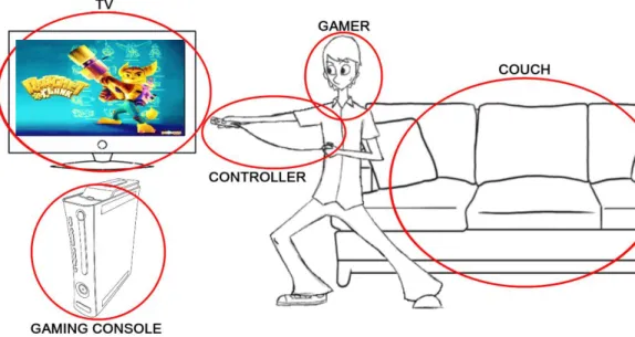
General System Design ... 4
Gaming Console ... 5
Controller ... 5
TV ... 7
Couch ... 7
Arduino... 7
Similar Products ... 8
Fitness Trampoline ... 8
DDR Pads ... 8
Wii Balance Board ... 9
Objectives ... 10
Concept Generation ... 12
Single Accelerometer ... 12
Nunchuck as Accelerometer ... 13
Multiple Accelerometers ... 13
Strain Gages ... 14
Buttons ... 14
Concept Selection ... 16
Method of Approach ... 17
Research ... 18
Wii Balance Board ... 18
DDR Pad ... 19
Accelerometer ... 21
Management Plan ... 23
Testing ... 26
Accelerometer ... 26
Buttons ... 30
Arduino... 34
3
Dynamic System Testing ... 37
Mario Kart 64 ... 38
Dance Dance Revolution ... 38
User Feedback ... 40
Building ... 40
Accelerometer ... 40
Accelerometer Protector ... 42
Buttons ... 43
Final Button Design ... 45
Recommendations and Conclusions ... 45
Button Size ... 45
Button Layout ... 46
Accelerometer Mount and Gyroscope ... 46
Get Working With Wii / Package Electronics ... 46
Manufacturing Process ... 47
Engineering Conclusions ... 48
Final Comments ... 49
References ... 50
Appendix A: QFD ... 52
Appendix B: Console Research... 53
Appendix C: TV Connection Types ... 55
Appendix D: Wii Mote Circuit Board ... 56
Figure 1. Wii Mote Printed Circuit Board, top view. ... 56
Figure 2. Wii Mote Printed Circuit Board, bottom view. ... 57
Chip listing: ... 57
Appendix E: Nunchuck Accelerometer Program ... 57
Appendix F: Wiimote Communication ... 64
Extension Controller Pinout ... 64
Nunchuck Data Format ... 64
I2C Protocol ... 65
Appendix G: Dynamic Testing/Expo Survey ... 68
4
Introduction
Childhood obesity is becoming a growing problem in the United States. According to the CDC, childhood obesity has more than tripled in the past 30 years [7]. It can lead to health problems previously reserved for adults, such as diabetes, high blood pressure, and high cholesterol. For the team WiiHopp project, we plan to turn a JumpSport mini-trampoline into a controller for the Nintendo Wii console. The hope is to help turn the problem of video games and the laziness surrounding them into an active solution to combat the problem of childhood obesity.
Our goal is to produce an add-on device for a mini-trampoline capable of interfacing with a gaming console. The device should be able to recognize typical trampoline motions, such as bouncing, stepping, and running along with bounce frequency and height. This will be done by integrating a series of sensors designing to interpret these motions. The device will then produce an output recognizable by the gaming system, thus allowing the user to use their trampoline to play their video games.
Background
General System Design
5
Gaming ConsoleThe game console is the piece of electronic equipment that does all of the processing and graphics computations necessary for the user to play a game. Its layout typically resembles that of a modern computer, consisting of a CPU, GPU, and RAM mounted to a motherboard. The console receives input from a controller and displays output on a TV. Nowadays, the controller-console connection is usually wireless. However, the console-TV connection is always wired. See the TV section below for more on the console-TV connection.
Consoles are categorized by their generation, with the latest being the 7th generation. The three current generation consoles are the Nintendo Wii, the PlayStation 3, and the XBOX 360, as seen below in Figure 2. For clarity, the terms gaming console and gaming system are interchangeable.
Figure 2. Current generation gaming consoles, from left to right: XBOX 360, PlayStation 3, and Nintendo Wii. [3]
Controller
The controller is the link between the gamer and the console. All game consoles utilize some sort of controller. Older consoles had wired controllers, but as of the current generation (7th) all major consoles now have wireless controllers. These are powered by either a pair of traditional AA batteries or a rechargeable battery pack [1]. PS3 and Wii use Bluetooth to connect wirelessly to their consoles, while XBOX 360 uses a proprietary radio frequency technology. The Bluetooth chip is the Wii controller is a Broadcom BCM2042 [2].
6
Each of the three modern consoles also has its own means of motion control. For the Wii, the motion sensing is built in, but for the other systems it is sold as an add-on (pictured below). They are called the PS3 Move and XBOX Kinect. In this document, the term “remote” will refer to a handheld motion-sensing device, while the term “controller” will refer to a device using buttons and joysticks to communicate.
New motion sensing control systems, as can be seen above, show that the PS3 and Wii use very similar systems consisting of a controller in one hand (left) and a motion sensing remote in the other. The remotes both contain 3-axis accelerometers. The Wii in particular uses an Analog Devices ADXL330 3-axis accelerometer1 [2]. The Wii Mote (Wii remote) detects its position through the use of a sensor bar. The sensor bar is placed above or below the TV and contains a series of infrared LEDs at a fixed spacing. Contained in the front of the Wii Mote is an infrared detector. Based on the orientation of the LEDs and the perceived distance between LEDs, the Wii Mote can determine where it is pointing. Note that this means of sensing only works when the Wii Mote is pointed towards the TV. Otherwise it must rely on its accelerometers for position detection.
The PS3 uses a similar yet more advanced system to accomplish the same goals. It uses a camera, called the PlayStation Eye, placed above the TV (in place of the sensor bar). Each remote has a glowing orb at the tip. The camera is used to locate the orb and can determine depth based on the orb’s size. Because the orb can be seen at all angles, this system allows the PS3 to maintain accurate position detection regardless of the orientation of the remote. In addition to a 3-axis accelerometer, the PS3 remote also contains a gyroscope to determine its rotation, as well as a magnetometer to determine its rotation relative to magnetic north. Data from all of these sensors is analyzed to determine the remote’s position and orientation in 3D space to within a millimeter.
The XBOX Kinect works quite differently. It utilizes two mounted cameras to identify the human body. The data from the two cameras is combined to create a 3D model of your body and the room in which you’re playing. It also has a RADAR system to determine your distance from the TV. Advanced
1
ADXL330 data sheet can be found at http://www.analog.com/static/imported-files/data_sheets/ADXL330.pdf
7
software is used to interpret this data and create a 3D skeleton of your body. This allows it to track your motions which are then used to control the game.
TV
In order to play a console, one must have a television or monitor to display the game. The TV is the primary means through which the gaming system interacts with the user. The user primarily interacts with the gaming system by pressing buttons, moving joysticks, and recently through certain full body motions recognized by the new motion control systems.
Consoles typically connect to a TV through composite-video cables, component-video cables, or HDMI (High Definition Multimedia Interface). Any display device, be it analog or digital, TV, monitor, or projector, will work with the console. The connection used depends upon user preference and the available connection types on the user’s TV. See Appendix A for a description of these connection types.
Couch
Sitting on a couch is the classic position for playing video games. However, as the new motion systems mature, household gaming is becoming more and more active. We hope that our trampoline controller will get players on their feet and bouncing, making the gaming experience more fun, more interactive, and healthier.
Arduino
Concept SelectionOur first choice for interfacing our controller with the Wii was through the Wiimote expansion port. This is a port in the back of the Wiimote into which extension controllers can be plugged, such as the Wii Nunchuck, classic controller, or Guitar Hero guitar. Our other options for interfacing with the Wii were to use the Gamecube ports or to create our own Bluetooth compatible device. The expansion port, however, has many advantages:
1. Maintains wireless – as opposed to using the Gamecube ports which are wired
2. Wiimote already has bluetooth built in – this simplifies our product and eliminates redundancy 3. Wiimote expansion port communicates through I2C, a simple and well-known protocol.
4. Possibility to power our extension from the Wiimote, thus eliminating the need for a battery pack.
5. For development purposes, we can have our extension controller disguise itself as different pre-existing controllers, allowing us to use it to try it out different games without having to develop our own software. This could not be done through the Gamecube ports.
Choosing Arduino
8
an Arduino with Wii controllers, and all of the code is readily available online, so we decided this was a good place to start.
We began by familiarizing ourselves with the Arduino IDE (Integrated Development Environment), programming language, and the use of buttons, LEDs, and sensors. We extended this into communicating between the Wii nunchuk and Arduino. The Arduino could read the Nunchuck’s acceleration and button values and perform calculations on them.
Similar Products
Fitness Trampoline
While we plan to integrate a fitness trampoline into our product, we are still in competition with existing mini trampolines. Trampolines like the JumpSport Rebounder, shown in Figure 5, are most commonly used for working out, either in a fitness class or with a workout video. We hope to maintain these uses while adding the ability to use the trampoline as a game controller.
Figure 6. Fitness Trampoline. The model pictured is a JumpSport Rebounder [6].
DDR Pads
Dance Dance Revolution (DDR) was a video game released in 1999. It began as an arcade game and grew in popularity once the game and the required dance pads were released for home game consoles. The DDR Pads are the simplest controllers we’ve examined, containing only buttons as input devices. Underneath the colorful surface of the gamepad exist three distinct layers: a top and bottom layer of
9
The foam has holes cut throughout it, so that when it is compressed by stepping on it, the top and bottom layers complete a circuit (button press). See Testing for details on the DDR Pad we disassembled.
Many people applauded the game’s incorporation of physical activity into gaming, as people playing at the higher difficulties can easily work up a sweat in a matter of minutes. Unfortunately, these gamepads are only usable with actual DDR games.
It should be noted that the DDR controller connection is the same as that of a Nintendo GameCube controller, which is also compatible with the Wii. This allows us to play any game on the Wii that can be played with a GameCube controller or a DDR pad.
Wii Balance Board
The Wii Balance Board was introduced in 2007along with the game Wii Fit. It is an attempt to incorporate more physical activity into gaming, with categories such as yoga, strength training, aerobics, and balance. While these are certainly healthy activities, we feel the balance board falls short in being able to deliver any type of full workout. Additionally, it is limited in the games with which it can be used. The balance board uses four strain gages, one in each corner, to measure the user’s weight and determine their distribution of weight. See Research for more information on the internal workings of the Wii Balance Board.
Although we have not been able to find another instance of a trampoline being used with a video game console, we have identified certain of its competitors. We hope that our product, when used in conjunction with a Wii, will replace a regular mini-trampoline used with a workout video. Other products, such as the Wii Balance Board and Dance Dance Revolution dance pads are designed to meld activity with gaming. Our product will accomplish this same goal through the arguably more fun medium of a trampoline.
10
Table 1. Pros and Cons of Similar Products
Fitness
Trampoline DDR Pads
Wii Balance Board
Disadvantages Doesn’t appeal to kids
Doesn’t appeal to adults
Not very intense (can’t jump or
run)
Workout
oriented
Can only be used with one type of
game
Limited use with other games
Only single player
Advantages Rugged design Multi-player Precise control
Variable intensity
Objectives
The overall goal of the project is to make a market ready trampoline that connects to a gaming console to give real time feedback of movement. The initial goal will be to get the trampoline to work with some existing games. Once this is completed, the trampolines outputs can then be used by software engineers to make games designed for trampoline jumping. The final product should meet the following engineering specifications.
I. Length of Assembly
We want the user to be able to pull the unit out of the box and have it ready to play within 30 minutes. This gives enough time to pull everything out of the box, bolt the legs of the trampoline together, and mount the sensory equipment. The final step will be to hook up the Wii trampoline to the Wii console which will be as easy as the press of a button.
II. Customer Survey on Use
We are requiring that all aspects of the device receive at least 80% positive feedback on use. We do not want to market an item that users do not want to use on a regular basis. The device should satisfy all customers in the customer description.
III. Customer Survey on Fun
We require that we have at least a 90% positive feedback on a survey of how fun the item is. We want our customer to be satisfied with the product.
IV. Energy Used by User
11
would be as low as possible so that anyone from any skill level can play with the device whether it is for fitness or fun.
V. Price
The price of the unit should be around $50 for the sensory equipment and the mounting system. This price does not include the price of the $300 dollar trampoline or the price of the $200 dollar Wii. The Wii Fit costs $100 which is like just having our sensory equipment and mounting system. The Wii and the trampoline already cost so much that a $50 add on is not a huge investment to mesh the two together
VI. Response Time
We need the device to be able to accurately relate input motion to a visual display as quickly as possible. The value of the upper limit came from the Wii Remote response time.
VII. Test Games
All devices testing should pass with at least 50% effectiveness on current games produced. We want the user to be able to use their current game collection with the device.
VIII. Test Movements
Since the device is going to be used by a wide range of users, our inputs must work accordingly. The device should be able to pick up all movements from our user range with 95% effectiveness.
IX. Customer Survey on Aesthetics
The device must produce 90% positive feedback for its looks. We want the customer to be able to leave the device in the living room or gym area all the time without the embarrassment of it looking sloppy.
X. Pass/Fail
12
Table 2. Project WiiHopp Formal Engineering Requirements For Risk L = Low, M = Medium, H = High
For Compliance A = Analysis, T = Test, S = Similarity to an Existing Design, I = Inspection Spec # Parameter Description Requirement or
Target (Units)
Tolerance Risk Compliance
1 Length of Assembly 30 minutes Max L T
2 Customer Survey on Use 80% positive Min H A
3 Customer Survey on Fun 90% positive Min H A
4 Energy Used by User 13 Calories/Min Max M T, S
5 Price $50 +/- $10 L A, S
6 Response Time 16 ms +/- 2 H A, T, S
7 Test Games 50% effective Min M T
8 Test Movements 95% effective Min H T
9 Customer Survey on looks 90% positive Min H A
10 Pass/Fail Pass M A, T, I, S
In summary, we hope to build on this newer generation of motion sensing controllers. We plan to use some of this latest generation motion sensing technology and adapt it to a trampoline. This will bring video games controllers and workouts to an all new level of interactivity.
Concept Generation
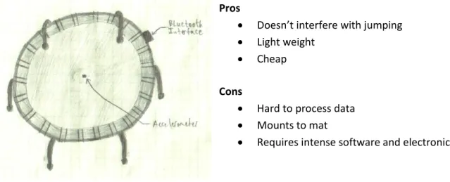
Single Accelerometer
This design uses a single accelerometer to take data then transfers it to the interface device which processes the data then sends a signal to the Wii via Bluetooth. This would allow for the jumping interface between the user jumping on the trampoline and the Wii game. We can also satisfy leaning, directional jumping, light and heavy jumping, as well as running with this one sensory device.
Pros
Doesn’t interfere with jumping
Light weight
Cheap
Cons
Hard to process data
Mounts to mat
Requires intense software and electronics
13
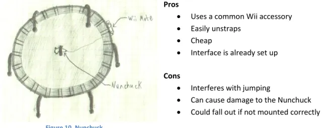
Nunchuck as Accelerometer
This design utilizes the equipment already made for Nintendo interface. The user would strap the Nunchuck to the underside of the trampoline then slide the Wii Mote into the remote holder. The Wii Mote is already set up to read the accelerometer data and interface with the Wii. This would satisfy all the same design requirements as the singular accelerometer would.
Pros
Uses a common Wii accessory
Easily unstraps
Cheap
Interface is already set up
Cons
Interferes with jumping
Can cause damage to the Nunchuck
Could fall out if not mounted correctly
Multiple Accelerometers
This design uses a multiple accelerometers located at different points on the mat. It would allow us to analyze the accelerations relative to other mat positions. With this we could map where the user is on the mat and potentially where they are in the air. This would satisfy the design requirements in the precious two concepts but allow for more accuracy.
Pros
Accurate mapping
Light weight
Doesn’t interfere with jumping
Cons
Super intense software and electronics
Difficult to calibrate
Hard to process data
Mounts to mat
Expensive
14
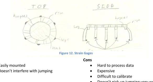
Strain Gages
This concept attaches strain gages to the legs of the trampoline. It would allow us to map the user’s position on the trampoline. This concept is very similar to the way the Wii balance board is made. Strain gages would be easily mounted but this could not be a standalone concept because we would not be able to correlate jumping to an output very easily.
Pros
Easily mounted
Doesn’t interfere with jumping
Cons
Hard to process data
Expensive
Difficult to calibrate
Doesn’t pick up jumping very well
Buttons
This concept adapts buttons to the surface of the trampoline mat. It would follow a similar construction to that of the DDR Pad, using conductive pads separated by a foam pad. However, it is a simple, straighforward, and cheap solution and allows the user to do a wide range of controlling.
15
Pros
Simple electronics
Already compatible with DDR games
Wide range of controls
Cons
Doesn’t take full advantage of bouncing
Complicates the trampoline mat
May make the mat less comfortable for regular bouncing
16
Concept Selection
After brainstorming for design concepts we must narrow our ideas down to the most feasible options. To do this we used a decision matrix with a list of the important requirements to our system. Please see table 3 below.
Table 3. Project WiiHopp Concept Selection Decision Matrix
Based on the decision matrix we found that the Nunchuck as an accelerometer and the button concepts definitely satisfied most of our requirements. Then, the other three concepts tied for third with a net score of zero. Concept A and C are similar to the ideas produced in concept B. Meaning they basically satisfy the same design requirements. Concept C provides slightly more accuracy than the other two options, but intensifies the problem. So based on this we are not going to pursue concepts A and C. Concept E is different than any of the other concepts and may satisfy some design requirements that the other concept might not be able to satisfy. For these reasons we do not want to throw this idea out just yet. We are going to continue research and development on this concept in anticipation of revising the decision matrix.
Selection Criteria
A Single Accelerometer
B Nunchuck as Accelerometer
C Multiple Accelerometers
D Buttons
E Strain Gages
Ease of testing 0 + - +
-Ease of integration 0 + 0 - +
Manufacturability 0 + 0 - +
Readability of Outputs + + + + 0
Range of Controls 0 0 + + 0
Software Intensity - 0 - +
-Electronics Intensity - 0 - +
-Trampoline Interference 0 - 0 - +
Cost + + + 0 0
Sum +'s 2 5 3 5 3
Sum 0's 5 3 3 1 3
Sum -'s 2 1 3 3 3
Net Scores 0 4 0 2 0
Rank 3rd 1st 3rd 2nd 3rd
Continue? No Yes No Yes Revise
17
Table 4. Project WiiHopp Console Selection Decision Matrix
Criterion Weight
Current Generation Consoles
Nintendo Wii PlayStation 3 Xbox 360
Rating Score Rating Score Rating Score
Price 3 10 30 5 15 4 12
Total Sales 7 10 70 5 35 6 42
2009 Sales 8 10 80 5 40 5 40
Audience Range 10 7 70 9 90 9 90
Sensory Equipment 4 5 20 10 40 7 28
3rd Party Compatibility 8 6 48 6 48 3 24
Fitness Oriented 6 8 48 3 18 6 36
Current Potential 8 7 56 7 56 2 16
Future Potential 8 10 80 8 64 5 40
Total 62 73 502 58 406 47 328
Table 4 is a decision matrix that we used to help us choose which console would be our primary focus to develop for during this project. The criterion weights vary from 1 to 10 and the ratings for each criterion also vary from 1 to 10. The higher the number, the better the console fulfills the criterion. The console with the highest score is the Nintendo Wii, followed by the PlayStation 3. The Xbox 360, according to our decision matrix, is the least desirable platform for development.
Method of Approach
In order to produce a video game controller, we plan to start by examining existing controllers. We are going to start with one of the oldest and simplest gaming systems, the Nintendo Entertainment System, and take it apart to figure out how its controller works. We then plan to move up to current generation controllers, such as the Wii Guitar. We’ll also examine our competitors’ products, like the Wii Balance Board and DDR dance pad to learn how they’ve used sensors with the Wii console.
18
I. Research
a. Disassemble II. Design
a. Decide on Basic sensors
III. Prototype (adjusting design based on how well the sensors work) a. Adapt to Wii
b. Get working on NES c. Get working on Wii IV. Test
a. Add more advance sensors (time permitting)
Research
Wii Balance Board
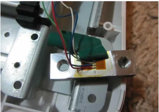
We disassembled the Wii Balance Board and discovered that it uses four strain gages to measure weight. One is located in each corner of the board. In addition, the strain gages are placed on finely machined steel bars which are put in bending in order to increase strain.
19
Table 5. Voltages measured between different wires on one of the strain gages. All values are in VDC. All
measurements made with an Omega multimeter.
White (VDC) Green (VDC) Blue (VDC) Red (VDC)
White -
Green 1.590 -
Blue 1.590 0.000 -
Red No Value 1.590 1.590 -
There seemed to be no readable signal between Red and White. The multimeter just read "1" or "-1." All other values were simply the voltage of a single AA battery (~1.5V) in the range 1.590±0.001 VDC. With Derek (148lb) standing on one of the strain gages we could measure a voltage increase of 0.002VDC.
DDR Pad
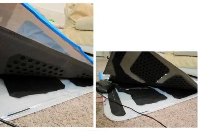
We cut open a DDR Pad to examine its internals and take some measurements. Our test setup can be seen below in Figure 15.
20
Seen in Figure 16 are three of the DDR Pad’s internal layers. The top is the colorful protective coating. The middle layer consists of the upper conductive sheet connected to a 4mm thick foam pad. (Foam thickness varies from manufacturer to manufacturer.) The bottom layer is the lower conductive sheet with a protective rubber pad below.
Figure 16. DDR Pad test setup
21
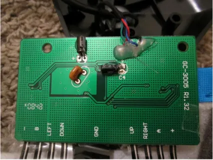
Figure 18. DDR Pad circuit board
The DDR Pad consists of 8 buttons: Plus, Minus, A, B, Up, Left, Right, and Down. These were conveniently labeled on the DDR Pad circuit board. We discovered that when any of the buttons are connected to the ground it responds as a button press. We measured 3.31VDC and 15mA between each of the buttons and ground. This voltage is reasonable, as the DDR Pad is supposed to receive an input voltage of 3.3VDC from the Wii.
Accelerometer
22
Figure 19. WiiHopp team member Derek Simon displaying accelerometer test setup
Figure 20. Close up of Wii Nunchuck attachment to trampoline
23
We were thrilled with these results, as it seems that one can clearly distinguish between different motions simply based on data from a single accelerometer. Each type of motion appears to create its own unique acceleration pattern. We are even able to sense leaning to a degree. When the gamer leans in one direction, he tilts the accelerometer. Although this does not change the magnitude of acceleration, it changes the relative direction of gravitational acceleration. This leads us to believe that we could possible sense leaning as well as bouncing with an accelerometer.
Management Plan
In order to stay on task in the design process we have put together a management plan that defines the responsibility of each team member.
Derek Simon is in charge of:
I. Gathering information about: a. JumpSport Trampoline b. Gaming Systems II. Documentation of progress on
III. Managing the sensory mounting system
Figure 23. Walking Figure 24. Running
Figure 21. Light bouncing Figure 22. Heavy bouncing
24
Ben Hoselton is in charge of:
I. Gathering information about: a. Sensory equipment b. Games
II. Manufacturing considerations III. Prototype fabrication
IV. Managing the sensory equipment system Jeff Christian is in charge of:
I. Gathering information about: a. Software
b. Modding II. Testing plans
III. Managing the software system
Also, in order to stay on track, we have a schedule that we are striving to fulfill. Winter Quarter
Finalize Problem Definition………..…..……….….………Jan. 25th Design Specifications……….…………..…….………..…….Feb. 1st Project Objectives……….……….…………...………….Feb. 3rd Concept Generation………..………..…….………Feb. 8th Concept Selection……….………..Feb. 10th Concept Design Review………..……….…....……..Feb. 15th Measure Sensory Outputs of Wii Mote……….………Feb. 17th Measure Sensory Outputs of Balance Board………..……….………..…….Feb. 22nd Measure Sensory Outputs of DDR Pad………..……….……….………Feb. 24th Static Calculations on Legs for Strain Gauges………..……….………..Mar. 1st Acceleration Measurements on Trampoline……….………..…Mar. 1st Design Specifications for Strain Gauges, Accelerometers, Etc……….……Mar. 3rd Buy Strain Gauges, Accelerometers, Etc………..……….……….Mar. 3rd Conceptual Design Report……….……….……..…..……Mar. 4th Conceptual Design Review……….……….………..…...……….Mar. 11th Spring Quarter
25
Writing PC Code to Analyze Accelerometers (ongoing)……….……..………Apr. 20st Calibrating/fine tuning DDR Type Buttons for Use on Trampoline………Apr. 27th Design Report……….………Apr. 28th Get Accelerometer working with Arduino….……….………..……May 4th Try fabric samples and tape……….May 4th Integrate DDR Type Buttons hardware to Arduino…………..………..May 11th Get emulator program working with button design……….….…May 11th Mounting single Accelerometer to mat…………..……..………..….….May 18st Integrating single Accelerometer hardware to Arduino……….…….May 18th Writing PC code to analyze single accelerometer (ongoing)……….……May 18th Get emulator program working with accelerometer design……….……….……..May 18th System Integration (Accelerometer and Buttons connected to Arduino)……...…..May 25th Writing PC Code that Analyzes all Systems Simultaneously (ongoing)…….…….……May 25th Get emulator program working with system………..……May 30th Critical Design Review………..………May 31st Project update report……….………..……June 2nd Fall Quarter
26
Testing
Accelerometer
Testing with the Nunchuck’s accelerometer has proved it is a worthy sensory device for use on the trampoline. We decided to mount the Nunchuck in a permanent location on the bottom of the mat so we could take more data and compile some programs to test its sensitivity in measuring jumping and leaning motions. A picture of the setup is shown below.
The system consists of a stretchy neoprene holder for the Nunchuck to keep it from slipping out, moving around, or getting crushed from a giant jump. The neoprene holder was then sewed to the bottom of the mat so that the accelerometer was in the middle of the mat. The Nunchuck is inserted into the neoprene holder and the extension is plugged into the Wii mote’s expansion port. The Wii mote interfaces wirelessly through Bluetooth communication to a computer. The computer can then run a program that accepts info from the Nunchuck and does a task. A schematic of the system is shown below.
27
We decided to use MatLab to write a test program since we found an existing interface online between the Wii mote and a PC running MatLab. Also, the MatLab language is widely used by mechanical engineers.
Using our initial data from the research section, we found that the X-axis of the accelerometer would be our jumping axis, the Z-axis would be our right and left directions (positive ΔZ would be left and negative ΔZ would be right), and the Y-axis would control our forward and reverse (positive ΔY is a forward motion and negative ΔY is a reverse motion). With this we developed a three dimensional interface between walking around on the trampoline and moving a ball on the screen. A screenshot of the play surface is shown below.
Figure 28. Screenshot of PC play surface
The details of the directional controls of the system are relatively simple. Basically, if the directional control acceleration is greater than the initial accelerations it moves in that direction (when you stand on the trampoline near an edge of the mat, gravity will act on the axis of the directional motion).
28
% Calibration
Wiimote.GetNunchukAccelState(); %gets initial accel state X1 = Wiimote.NunchukAccel.X %show in command window
Y1 = Wiimote.NunchukAccel.Y Z1 = Wiimote.NunchukAccel.Z
Then we can relate the change in the accelerations to the initial accelerations.
while (~isButtonPressed('HOME'))%exit program if HOME button pressed
Wiimote.GetNunchukAccelState();%continues to get accel state X = Wiimote.NunchukAccel.X;
Y = Wiimote.NunchukAccel.Y; Z = Wiimote.NunchukAccel.Z;
%Bi directional controls
if(Z>Z1+tolerance && Y>Y1+tolerance)%move left and up %controls to make ball move up and left
else(Z>Z1+tolerance && Y<Y1-tolerance) %move left and down %controls to make ball move down and left
else %accels to move in another direction...
This process is done throughout the other directions from hardest directional condition (directional) to easiest directional condition (singular directions). So that if the user trips a bi-directional control first it registers as a bi-bi-directional control, but if a singular bi-directional control came first in the order it would trip that control first and move in a singular direction.
The tolerance value is to set the sensitivity of the acceleration values. The difference has to be greater than some tolerance value. This allows the programmer to change how easy it is to make the ball move in the desired direction. A small tolerance means the user only needs to apply a small force to the mat to get the ball to move directionally, a large tolerance means the user has to jump on the mat to get the program to pick up a directional movement.
Now that we have covered the two dimensional directional controls we can introduce a jump to the system using the X-axis.
if(X < jump) % jump is the acceleration required for a jump (-20 m/s)
hide(obj); % hides previous circle
obj = drawCircle(l, s+j, p); % draws new circle a location j above the initial location and increases the size of the ball to give a 3 dimensional effect
pause(jumppause); % Air time hide(obj); % hides in air object
obj = drawCircle(l, s, o); % draws initial object pause(0.001);
else
% continue with next statement end
29
The jump statement can now be placed into each directional flag so that if a directional flag is raised, it will also check to see if a jumping flag is raised. This will allow for directional jumping. An example of this will not be shown (see the .m file in Appendix E for code).
The final step is to complete the program with a jumping flag so that if there are no directional flags raised, the object will still jump if a jumping flag is raised. Testing is simplified by increasing the tolerance to an unreachable amount and the accelerometer will only flag a jump. Testing of the directional controls can also be simplified by increasing the jump value to an unreachable acceleration and decreasing the tolerance to a value seen while leaning on a side of the mat.
The program will continue to run until the HOME button on the Wii mote is pressed. Pros
Works great for directional controlling and jumping
Doesn’t get stuck in loops
Allows user to set different tolerances for directional or jump movements Cons
Uses a simple flag system that allows a left before a right
o This causes problems with ball motion when jumping too hard on the
trampoline because initially a right jump is read as a left jump. This is due to the swinging motion of the mat as the accelerometer moves down.
The accelerometer test program is able to reliably interpret the user’s motions. Upon jumping or leaning, it will consistently respond by moving by ball (as seen in Figure 29) in the intended direction. Overall, our testing demonstrates that a mounted accelerometer will allow directional and jump controls.
Future Additions to Code
Calorie values could be calculated from the users mass and acceleration values. We can introduce a calories burned in game play to see if we can get accurate measurements.
Stopping at screen limits
o As of right now the ball will continue infinitely off the screen once it leaves the window
Smoother jumps and directional movements Next Step with Accelerometer Design
30
Buttons
Through further testing and concept generation, we have modified and improved our original button design. At first, the buttons were going to be placed on the mat, or jump surface itself, as shown in the concept generation section. After further consideration to the function of the system we are designing, it was decided that we would try and preserve the jump surface as much as possible. At first our idea was to move the buttons to the edge of the mat and arc them according to the mat’s circumference. In this design, the buttons appeared too small and hard to distinguish and they were still on the mat itself. This led us to our final design concept: placing the buttons off the mat and inserting them into the dense foam pads that cover the trampoline’s bungees. In this way the buttons will be large, clear, easy to step on, and the mat surface is perfectly preserved for the ultimate jumping experience.
The button assembly consists of a lower layer of very dense thick foam (trampoline bungee cover), a flexible plastic sheet used to hold the lower conductive layer, a thin foam of medium density with holes in it to allow contact between the upper and lower conductive layers, and a top conductive layer attached to another flexible plastic sheet for stability. This layered sandwich is what is inserted into the canvas flaps that cover the bungees of the trampoline. When stepped on, the two conductive layers connect and send a signal in the form of a button press to the Wii, Arduino, or computer.
This eventual button configuration sounds simple enough, but a great deal of testing went into material selection. The dense foam came with the trampoline and is almost ideal for the button design, so it has remained unchanged. The conductive layers took much iteration to come up with a final design. At first we considered using conductive cutouts from our DDR pad but we did not like the cheap and flimsy feel of the material, as well as the crinkling sound it made. Next, we tried using aluminum screen. This not only was not a very good conductor, it was very difficult to attach to the button assembly. It had trouble connecting through the holes, and it permanently deformed after repeated use. We have narrowed the material down to either a conductive copper tape or highly conductive EMF shielding fabric. These materials have extremely low resistance, are flexible, and are easy to attach to other materials. We first tested all of these conductive layer designs on the floor and connected their leads to LEDs. We chose our design based on which material types most consistently and stably lit up the LED. We discovered the need to keep the conductive material from creasing and sliding around. We settled on a linoleum type material that is tough, flexible, won’t fray or crack, and holds glue very well.
31
Lastly, we needed a foam layer with holes in it to allow the conductive layers to make contact. We tried using the foam from the DDR pad, but it was too thin and flimsy and would give us false connections. Next, we tried a car wash sponge but found it to be too thick, dense, and difficult to test. We have narrowed down our foam selection to two types: ½ inch craft foam of fairly low density and thin rubbery foam of medium density used to line toolboxes. Both foams work so we have not yet decided between these two foam types and are currently testing both. For the holes in the foam, we
are using a ½ inch leather punch to make rows and columns of holes in the foam. Each hole is about 1” apart in each row (edge to edge distance) and the columns are spaced in the same fashion.
We have successfully used these buttons on the trampoline and to play emulator games on the computer such as SNES’ Mega Man X and classic Super Mario Bros on the Wii.
Next Steps
The next step for the buttons is to finalize our material choice and build a complete set of 6 buttons. Once this is done we will run the wires around the trampoline and clean up the connection to the Arduino by soldering them to pin headers or using a known type of data connection such as USB. We have yet to decide on a suitable method for sealing the buttons. For our prototypes we have been taping the layers together, but we would like to sew them together for our final product.
We also plan to conduct static and dynamic tests of our different button designs in order to quantify their reliability. For static tests, we will attach each button to an LED that will turn on when the button is pressed. We’ll then load the button with weight, increasing the weight until it registers a button press. For a dynamic test, we will have one person play a DDR game while another person watches and tracks the accuracy of their dance steps. DDR games classify each step as either “perfect,” “great,” “good,” or “miss.” After a large number of button
Figure 30. Foam test sample with holes
32
presses (~100) we’ll examine the data to see if certain buttons have a higher hit rate than others and use that design in the rest of our buttons.
33
34
Arduino
We began specifically developing the Arduino as a Wiimote extension. We purchased an extension cable, cut it in half, and soldered it to a pin header in order to connect the Arduino to the Wiimote (Figure 36). We rewired the Arduino’s circuit board to contain 6 buttons (Figure 37). Once this was done, we made some modifications to existing code online until the computer was able to recognize the Arduino as any type of existing extension controller. Which type of extension controller is determined by certain variables in the Arduino code.
The Arduino code maps Arduino buttons to certain Classic Controller buttons. Using a Mac program called DarwiinRemote, we’ve been able to get a computer to connect to the Wiimote via Bluetooth and recognize the Arduino as a Nintendo Classic Controller extension. DarwiinRemote is a Mac program that allows one to connect a Wiimote (with extensions) to a computer over Bluetooth. It then maps the extension controller buttons to specific keyboard keys allowing the Wiimote to be used to play games on the computer. We’ve also used a Snes9x, a Super Nintendo emulator, to play SNES games using the Arduino. Snes9x maps keyboard keys to SNES controller buttons. Thus, in this setup, the Arduino buttons correspond to Classic Controller buttons, which are mapped to keyboard keys, which are mapped to SNES controller buttons.
Once all of these are set properly, play goes quite smoothly. There is no detectable lag in the Arduino’s output and all button presses are consistently recognized. We have tried this setup on an actual Wii but have had limited success. The Wii will only recognize the Arduino as Nunchuck extension, regardless of how it’s programmed to be recognized. As a Nunchuck, we
Figure 34. Arduino to Wiimote connection cable
35
can successfully send button and joystick values, but not accelerations. We plan to continue testing our controller on a computer and developing it for use with the Wii.
See Appendix F for details on the Wiimote expansion port, Wiimote extension signals, and I2C protocol.
Static Button Testing
In order to asses our different button designs, we designed a set of static and dynamic tests. For the static test, we wanted to measure the force required to activate a button press. The static test consisted of wiring each button to an LED and placing it on a scale. We slowly added weight to the button until the LED turned on, indicating a button press.
We repeated this process processing each button in both a forward foot position and a sideways foot position (Figure. 36 below), since these are the two ways in which we expect the buttons to be pressed, depending upon their position on the trampoline mat. We used actual human feet in order to most accurately simulate an in-game setup.
The results from these tests are seen below in Figures 37-39.
The most significant differences in the buttons we tested were in hole size and spacing of the foam layer. We tested combinations of large and small holes with sparse and dense spacing as defined below.
Table 6. Quantified button parameters
Small Hole Diameter Large Hole Diameter Sparse Dense
.375 in 0.50 in 1.5 buttons/in2 2 buttons/in2
It is worth noting that we had been using all of these buttons ahead of time, so we knew that all of the designs worked. With this test we sought to quantify what made certain buttons better than other
36
Figure 37. Static button force test results (forward foot placement)
Figure 38. Static button force test results (sideways foot placement)
Based on these test results, the each button appears to perform consistently. In other words, Button 1 is consistently requires the third greatest amount of force to activate. We decided to plot the average force required to activate each button, as seen below.
0 10 20 30 40 50 60 70 80 90 100
0 1 2 3 4 5 6 7 8 9 10
Fo rc e (l b f) Test # Button 0 Button 1 Button 2 Button 3 Button 4 Button 5 0 20 40 60 80 100 120 140 160
0 2 4 6 8 10
37
Figure 39. Analysis of static button tests. Each line represents the average value of force required to make each button connect
The results of this test were fascinating. It is clear that the buttons fall into two distinct groups. However, once we actually labeled each button with its appropriate hole layout, we arrived at an interesting result. The buttons with small holes took significantly more force than those with large holes. This is expected. But, this force paled in comparison to the force difference as a result of spacing between the holes.
In comparing, sideways and forward button presses, we found that the relative ranking between buttons was consistent. This was a reassuring result. However, the forces were not the same. On average, it took 1.4 times as much force to press the button when stepping sideways than when stepping forward. We attribute this difference to the fact that a sideways step is distributed over a greater surface area than a forward step (one’s heel is contacting the button in addition to the ball of their foot). This increase in surface area means that more force must be applied to achieve the same amount of pressure.
From these results, we conclude that while hole size is very significant, hole spacing is much less significant. They can be used together as coarse and fine adjustments to tune the buttons to the desired activation force. In our case, we decided a button sensitivity of 25 lbf was most desirable, and tuned the buttons accordingly.
Dynamic System Testing
Dynamic button tests were performed using a sample size of 9 players. We chose two different games to play, each of which highlighted a different component of the controller. The game Dance Dance Revolution (DDR) used all of the buttons on the trampoline while Mario Kart 64used the accelerometer.
0 10 20 30 40 50 60 70 80
1 1.2 1.4 1.6 1.8 2
38
Mario Kart 64For Mario Kart, each player raced one time with a traditional controller and then again using the trampoline. The time differences, in favor of the traditional controller, are displayed in the table below. The testing results confirm that the trampoline is a competitive and viable controller option.
Table 7. Increase in Mario Kart lap times while using trampoline as the controller. Since time differences are small, we see that the trampoline is a competitive alternative to a traditional controller.
Δtave 1.73 seconds/lap Last Lap Δtave 2.24 seconds/lap
On average, users raced 1.73 seconds slower per lap when playing on the trampoline than they did with a traditional controller. However, we attribute much of this difference to adjusting to the new controller scheme. Most people all familiar with a traditional video game controller, but no one has used the steering mechanism implemented in our trampoline, and thus, we expect a learning curve.
On average, players lap times decreased throughout the race. This was true with both the trampoline and traditional controllers. However, in comparing the time differences for only the last lap, we found that the trampoline produced times that were slower by 2.24 seconds. This is greater than the average difference for all laps. From this we conclude that improvement with the trampoline is slower than with a traditional controller. In other words, it takes longer to learn and adjust to the trampoline’s controller layout than to the traditional controller. However, we believe that with enough practice, the trampoline will prove to be a controller that is competitive with traditional controllers. As it is, the difference is on the order of a few seconds, which is minor enough to demonstrate that the trampoline is a viable controller alternative.
Dance Dance Revolution
39
Figure 40. Button accuracy for trampoline directional pad in DDR. Since accuracy is similar for each button, we conclude that all buttons are performing equally well.
Because the distribution of accuracy is very similar for each of the directional buttons, we conclude that all of the buttons are performing equally well. Additionally, below we have compared the percentage misses for each button. (Perfect, great , and good all qualify as hits with varying accuracy).
Figure 41. Percent of missed button presses in DDR. Since percentage misses is 5% or less for each button, this indicates that all buttons perform reliably.
Left Down
Up Right
0 10 20 30 40 50 60 70
% Perfect
% Great
% Good
% Miss
0.0 0.5 1.0 1.5 2.0 2.5 3.0 3.5 4.0 4.5 5.0 5.5
Left Down Up Right
%
M
40
This graph indicates that users were able to successfully press all buttons at least 95% of the time. Additionally, with numbers this small, we assume that most, if not all misses are due to user error and not the malfunctioning of our buttons.
We believe that button placement can explain the difference between the % Misses for each button. The Up button, with the lowest miss rate (<1%) is placed directly in front of the user and is easily visible to the player. The Left and Right buttons are also easily accessible, but are more in the player’s peripheral vision. This results in similar miss rates that are higher than that of the Up button. The Down button is located behind the player, making it difficult for him/her to see the button and know where he/she is stepping. Thus, the Down button produced the greatest number of misses.
The results of these tests lead us to believe that our trampoline controller functions reliably. Users are able to play various games with the controller and to achieve similar results to the traditional controller.
User Feedback
We prepared a survey for all users of our system. The results from the survey were generally very positive and we gained some valuable suggestions for future modifications. A summary of the quantitative results can be seen below. The entire survey can be seen in Appendix G.
Table 8. Average feedback scores from users. Scores are on a scale from 1 to 10, where 10 is best. Average
Overall Functionality 7.3 Lag/sensitivity 7.3
Ease of Use 7.2
Overall Enjoyment 8.9
Building
Our final product will consist of a trampoline outfitted with buttons and an accelerometer in the center of the mat. The buttons will be labeled on the pad surrounding the trampoline. Both the buttons and the accelerometer will connect to the Arduino which will interface with a Wiimote.
Accelerometer
41
design, including communication with the Arduino and mounting to the trampoline mat. It also reduced the danger of bottoming out and crushing the accelerometer, since the bare accelerometer is much slimmer than the Nunchuk.
In order to attach the accelerometer to the Arduino we have run a wire out to the center of the trampoline mat. The wire is threaded into the mat at 3 support points. The connection must be solid enough to withstand heavy bouncing without transferring any extra vibrations to the accelerometer. We have also given it enough slack (~4 inches) at the transition across the bungees in order to absorb bounces without being put in tension.
By default, the Arduino reads in XYZ accelerations as integers from 0 to 1023. In order to adjust for any offset in initial accelerations, we have added a button to zero the values. After the button is pressed, all accelerations are read relative to this zero reference point.
In order to send the accelerations as joystick values, they must be converted to integers between 0 and 63 with 31/32 being the center (no movement/no acceleration). We multiply the accelerations by the factors necessary to both reduce it to this range and ensure that the range of accelerations experienced on the trampoline spans the range of joystick values. With this conversion, the Arduino is plugged into the Wiimote disguising itself as a Classic Controller. The Wiimote is then connected to the computer through Bluetooth using a program called Wiiji. While there are many computer programs that can be used to simply connect a Wiimote, this one is unique in that it recognizes the Classic Controller’s joysticks as computer joysticks. The Wiimote-Arduino-accelerometer combination can then be used to play any game that will run on a computer. However, in order to simulate Wii games, we have been testing with games on a Nintendo64 emulator. Nintendo64 is an older generation gaming console from Nintendo. An emulator is a program that runs programs or games designed for a different system, thus allows use to test N64 games on a computer.
Using the accelerometer as a joystick only uses the X and Y accelerations. This leaves the Z acceleration to be mapped to another button. For example, when the user exceeds a certain value by jumping, the player’s character could be made to jump. This action could be changed to suit different games.
42
Figure 42. Mounted accelerometer with brass rods sewed into mat
For final manufacturing we are going to use a glue that cross threads into the trampoline surface then cover the accelerometer with a polypropylene surface. So the accelerometer would be glued then sandwiched into place so that it was protected from moving and from users. The next step would be to add some protection for the circuit board. Since the accelerometer is in the center of the mat, it is in danger of being crushed if someone bottoms out the trampoline. To protect the accelerometer we are going to add a foam donut that goes around the circuit board. When bottomed out, the accelerometer will not experience pressure because the force will be absorbed by the foam pad surrounding the accelerometer.
Accelerometer Protector
When bouncing on the trampoline, it is quite easy to bottom it out when jumping in the middle of the mat. The problem with this is the accelerometer has to be mounted directly in the center of the mat in order to detect leaning in all directions equally. We decided to make a foam ring to surround the accelerometer that protects it when the trampoline is bottomed out. This assembly can be seen in Figure 37. The ring is attached to the mat using a standard hot glue gun which worked unexpectedly well. After the ring was secured we tested it by jumping on the trampoline hard enough to bottom out the mat on a hard wood floor. We did this multiple times and the accelerometer remained unharmed, validating our design.
Brass rods
43
Figure 43. Mounted accelerometer with brass rods sewed into mat
Because the hot glue worked so well in attaching the protection ring, this gave us the idea that the accelerometer itself may be able to be hot glued directly to the mat as well. Our idea was to use super glue (which attached better to the accelerometer board than hot glue) to attach a thin foam pad directly to the accelerometer. Then we would use hot glue to glue the foam/accelerometer assembly to the mat itself in the same way we attached the protector ring.
Buttons
44
Figure 44. Current trampoline control layout.
Now that we have a few buttons that work relatively well, we need a way to quantify the quality of each button design so that we can choose the best design for our project. We came up with a couple of different tests for static and dynamic testing of the button assemblies. The static test can be accomplished with a shoe sole and some weights. We will place the button on a hard surface and connect it to our Arduino circuit that can read a button press. Then we will place the shoe sole on top of the button in different orientations and then place weights on the shoe sole until we received a button press through the Arduino.
The dynamic testing will be completed using the trampoline and a DDR game. We will play the DDR game with a certain button configuration then tally up the number of good and bad button presses. This will be done through the DDR game itself. At the end of the song the DDR game tells the user how many good and bad button presses they had. We will record this data with multiple users in order to get a fair reading of each button configuration. The DDR statistics window is shown below.
X-axis
Y-axis Accelerometer
45
Figure 45. DDR statistics shows perfect, great, good, ok, bad, and missed button presses.
Final Button Design
After reviewing the data from our static button test we rebuilt all of the buttons in a consistent manner using the top test result of densely spaced large holes. During the rebuild we also added electrical quick-releases to each button for ease of removal or repair. This was done not only so we could investigate a button problem but also so we could try different buttons in different positions on the mat to verify their sensitivity. Afterwards we tested all of the buttons again to make sure they were of the appropriate sensitivity. These results were then validated during our dynamic testing session where all buttons performed excellently and users did not notice any button performing worse than any other.
Recommendations and Conclusions
Button Size
46
Button Layout
Another suggestion we got from our users at the dynamic button testing was on the location of the buttons. DDR pads have users stand directly in the center of the mat, and directional buttons are directly in front or to the side of the user. D-pad and joystick controllers work the same way. Our controller has left and right in front of the users side (Refer to Figure 44). This button layout is not intuitive to most people and the DDR game involves constant looking at the screen. We found that most users did adjust accordingly as there is a learning curve to all new controllers but it was slower than we would have liked to see. We designed the button layout based on the existing pads in the trampoline we received from JumpSport, so we weren’t left with a whole lot of options with our lack of sewing skills. Our suggestion is to redesign the button layout to have left and right parallel with the TV and centered with respect to the user. This will give the user the most intuitive button layout. The A button could then be placed in between up and right, B button between up and left, 1 button between down and right, and the 2 button between down and left. This would allow for a lot of available buttons for menu selection and scrolling. Then game play could be achieved with the larger directional buttons or an occasional tap on a smaller A button. Figure 13 gives an example of a possible setup.
Accelerometer Mount and Gyroscope
We ran into issues with trying to mount things to the mount without inhibiting the use of the trampoline or damaging the material. Initially we sewed the accelerometer into the mat to hold it securely in place. This worked great for our proof of concept but we had trouble coming up with a mount design that could be easily manufactured. The hot glue on the accelerometer protector seemed to work well but we were not able to test this method. Hot glue may be a viable option for mounting but would have to be further analyzed.
A gyroscope may be a beneficial piece of hardware for the controller. An accelerometer works great for getting the jumping accelerations to figure out if the user is jumping, running, walking, etc., but a cheap accelerometer doesn’t allow for a large range while leaning on one side of the trampoline. A gyroscope may be a better piece of hardware for this aspect of the controller. If the user were jumping on the left side of the trampoline, the accelerometer outputs would make it hard to figure out that left were being pressed. A gyroscope on the other hand would show a rotation to the left then back to center. It would clearly show that the user was trying to control to the left.
Get Working With Wii / Package Electronics
47
writing a Wii Homebrew application in order to test the controller then eventually getting it to work with current games or even making new games specifically for the controller.
We used an Arduino microcontroller which is considered a general purpose
microcontroller. We are not experts on microcontrollers and don’t know where to start in order to find a microcontroller that satisfies exactly what we need it to do. This would be a crucial step to minimize costs on the product. The circuit board and wiring could also be minimized in order to save manufacturing costs as well as the total size of the unit. It would be nice to have the controller completely wireless, either by plugging the unit into a Wii mote or by
incorporating Bluetooth into the device so it communicates directly to the Wii. We didn’t look into power use of the unit either. The final unit should be battery powered and be able to power the device for as long as a Wii mote. The device could be powered by the Wii mote itself just like any other Wii extension.
Users told us that the stability bar was a must have for the controller. It allowed users to shift their weight faster in reaction to game motions. One suggestion for the bar is to add buttons directly to it so that the user does not need to hold the Wii mote for gameplay. For instance, the acceleration and brake buttons for Mario Kart could be incorporated in the bar so the user can keep a firm grip on the stability bar.
Manufacturing Process
Another important step in developing the product further is thinking towards the manufacturing process of the controller. The buttons need to be designed in a way that’s cheap and easy to manufacture. Manufacturability should be taken into consideration for the
mounting of the hardware and the packaging of the electronics. The whole product needs to be streamlined for manufacturing. One suggestion for the button design is the conductive material could be a conductive paint that could be sprayed or brushed on. The accelerometer and any other hardware mounted to the mount could be adhered with some type of hot glue.
48
Engineering Conclusions
After completion of a project it is important to re-evaluate the original design specifications. Table 2 is partially reproduced below for reference.
Table 2. Project WiiHopp Formal Engineering Requirements Spec # Parameter Description Requirement or Target
(Units)
Tolerance
1 Length of Assembly 30 minutes Max
2 Customer Survey on Use 80% positive Min
3 Customer Survey on Fun 90% positive Min
4 Energy Used by User 13 Calories/Min Max
5 Price $50 +/- $10
6 Response Time 16 ms +/- 2
7 Test Games 50% effective Min
8 Test Movements 95% effective Min
9 Customer Survey on looks 90% positive Min
10 Pass/Fail Pass
Upon evaluation of our final product we can conclude that some requirements were met, some were not, and some were found to be irrelevant, not available, or negligible.
Specification 1
This specification is irrelevant to our project as we did not focus on the manufacturability or packaging of a final design, but more on a proof of concept. We do believe, however, that this requirement can be met if our project continues along the same development path.
Specification 2 and 3
These requirements were met. Specification 4
In our project testing we did not asses heart rates of direct energy during the dynamic testing session, however, we proved that the product could be variable intensity and therefore can say that we met this target.
Specification 5
For the same reasons as Specification 1, we believe that this requirement can be met. Specification 6
49
Specification 7
Our system was designed to work with several games but can be made compatible with any game through software. We did not focus our project on software development so this requirement does not apply to our project.
Specification 8
As shown in our Dynamic system testing of buttons, users performed with an average missed button hit of only 5%. We can safely attribute this to user error though and state that this requirement is therefore satisfied.
Specification 9
This specification is irrelevant as we did not design our product to involve aesthetics or survey users on the overall system appearance.
Specification 10
The previously specified pass/fail requirements of wireless capabilities, and battery powered were achieved.
All of these engineering requirements were also validated through overall product functionality and user enjoyment.
Final Comments
The project was a total success! Based on the results from our user feedback, and our own use of the system, we believe that we have demonstrated and built a viable design for integrating a trampoline with a video game console. We receive user feedback such as, “Tons of fun!,” “great for the casual gamer,” and “Flat ground will never be good enough again!”