General Commands Reference Guide F
TRACE32 Online Help TRACE32 Directory TRACE32 Index
TRACE32 Documents ... General Commands ... General Commands Reference Guide F ... 1 FDX ... 8
Trace Methods 8
Trace Method FDX 9
FDX.METHOD Select communication channel 10
FDX.Arm Arm the trace 11
FDX.AutoArm Arm automatically 11
FDX.AutoFocus Calibrate AUTOFOCUS preprocessor 11
FDX.AutoInit Automatic initialization 11
FDX.AutoTEST Continuous measurement 11
FDX.BookMark Set a bookmark in trace listing 11 FDX.Chart Display trace contents graphically 11
FDX.Chart.DistriB Distribution display 12
FDX.Chart.Func Function activity chart 12
FDX.Chart.GROUP Group activity chart 12
FDX.Chart.Line Graphical HLL lines analysis 12
FDX.Chart.sYmbol Symbol analysis 12
FDX.Chart.TASK Task activity chart 12
FDX.Chart.TASKFunc Task related function run-time analysis (legacy) 12 FDX.Chart.TASKSRV Service routine run-time analysis 13
FDX.Chart.TASKState Task state analysis 13
FDX.Chart.VarState Variable activity chart 13 FDX.CLEAR Clear FDX communication buffers 13
FDX.CLOSE Close FDX files 13
FDX.ComPare Compare trace contents 13
FDX.DISable Disable the trace 13
FDX.DISableChannel Disable FDX communication 14
FDX.DRAW Visualization of trace data 14
FDX.ENableChannel Enable FDX communication 14 FDX.EXPORT Export trace data for processing in other applications 14 FDX.FILE Load a file into the file trace buffer 14
FDX.FindChange Search for changes in trace flow 14 FDX.GOTO Move cursor to specified trace record 15
FDX.InChannel Inchannel state display 15
FDX.Init Initialize trace 15
FDX.List List trace contents 15
FDX.ListNesting Detailed function nesting 15 FDX.LOAD Load trace file for off-line processing 15
FDX.Mode Set the trace operation mode 15
FDX.OFF Switch off 15
FDX.Out tbd. 16
FDX.PROfileChart Profile charts 16
FDX.PROfileChart.DIStance Time interval for a single event 16 FDX.PROfileChart.DURation Time between two events 16 FDX.PROfileChart.GROUP Group profile chart 16
FDX.PROfileChart.Rate Event frequency 16
FDX.PROTOcol.Chart Graphic display for user-defined protocol 16 FDX.PROTOcol.Draw Graphic display for user-defined protocol 17 FDX.PROTOcol.EXPORT Export trace buffer for user-defined protocol 17 FDX.PROTOcol.Find Find in trace buffer for user-defined protocol 17 FDX.PROTOcol.List Display trace buffer for user-defined protocol 17 FDX.PROTOcol.STATistic Display statistics for user-defined protocol 17
FDX.Rate Select sampling rate 17
FDX.REF Set reference point 17
FDX.RESet Reset command 18
FDX.SAVE Save trace for postprocessing in TRACE32 18 FDX.SelfArm Automatic restart of trace recording 18
FDX.SIZE Define buffer size 18
FDX.SnapShot Restart trace capturing once 18 FDX.state Display trace configuration window 18
FDX.STATistic Statistic analysis 18
FDX.STATistic.DIStance Time interval for a single event 18 FDX.STATistic.DistriB Distribution analysis 19 FDX.STATistic.DURation Time between two events 19 FDX.STATistic.Func Function runtime analysis 19 FDX.STATistic.GROUP Group run-time analysis 19 FDX.STATistic.Ignore Ignore false records in statistic 19 FDX.STATistic.InterruptIsFunction Define statistics interrupt processing 19
FDX.STATistic.Line HLL-Line analysis 19
FDX.STATistic.LINKage Per caller statistic of function 20 FDX.STATistic.Measure Analyze the performance of a single signal 20 FDX.STATistic.PreFetch Prefetch detection 20 FDX.STATistic.Sort Specify sorting criterion for statistic commands 20
FDX.STATistic.TASK Task activity statistic 20 FDX.STATistic.TASKFunc Task specific function run-time analysis 20 FDX.STATistic.TASKKernel Task analysis with kernel markers (flat) 21 FDX.STATistic.TASKSRV Analysis of time in OS service routines 21 FDX.STATistic.TASKState Performance analysis 21 FDX.STATistic.TASKTREE Tree display of task specific functions 21 FDX.STATistic.TREE Tree display of function run-time analysis 21
FDX.STATistic.Use Use records 21
FDX.TimeStamp Configure timestamps for LOGGER 21
FDX.Timing Waveform of trace buffer 22
FDX.TraceChannel tbd. 22
FDX.TRACK Set tracking record 22
FDX.View Display single record 22
FDX.ZERO tbd. 22
FIFO ... 23
FIFO Display on-chip trace FIFO 23
FLAG ... 24
Flag System of TRACE32-ICE 24
Applications 25
Problems 25
Flag System of TRACE32-FIRE 26
Applications 26
Problems 26
FLAG.Delete Delete flags 26
FLAG.Init Initialization 27
FLAG.List Display flags 27
FLAG.ListFunc Code-coverage functions 28
FLAG.ListModul Code-coverage modules 31
FLAG.ListVar Code-coverage variables 33
FLAG.OFF Switch-off flag system 35
FLAG.ON Switch-on flag system 36
FLAG.RESet Reset 36
FLAG.Set Set 36
FLAG.SetSec Mark sections 37
FLAG.state State 37
FLASH ... 39
FLASH.AUTO Auto programming of FLASH 40
FLASH.BSDLaccess Enables FLASH access via boundary scan 41 FLASH.CFI Generate FLASH declaration by CFI 42
FLASH.CHANGETYPE Changes the FLASH type 46
FLASH.CreateALIAS Create address alias 52 FLASH.Delete Delete entry in FLASH definition table 53
FLASH.Erase Erase FLASH 54
FLASH.List Display FLASH definition table 55
FLASH.LOCK Lock FLASH 56
FLASH.MultiProgram Simultaneous programming of flash sectors 57 FLASH.OFFSET Change FLASH control address 57
FLASH.Program Program FLASH 58
FLASH.ReProgram Re-program FLASH 59
FLASH.RESet Reset FLASH definition table 60
FLASH.state FLASH programming dialog 61
FLASH.TARGET Define target controlled algorithm 62 FLASH.TARGET2 Define second target controlled algorithm 69
FLASH.UNLOCK Unlock FLASH 70
FLASH.UNSECUREerase Unsecure a device 72
FLASHFILE ... 73 FLASHFILE NAND flash and serial flash devices 73 FLASHFILE.BSDLaccess Enables FLASH access via boundary scan 73 FLASHFILE.BSDLFLASHTYPE Define FLASH type 74
FLASHFILE.CONFIG Configure NAND FLASH 74
NAND FLASH 74
Serial FLASH 75
FLASHFILE.COPY Copy to NAND FLASH 75
FLASHFILE.COPYSPARE Copy to spare area of NAND FLASH 76
FLASHFILE.DUMP Dump NAND FLASH 77
FLASHFILE.Erase Erase NAND FLASH 78
FLASHFILE.GETBADBLOCK Get the bad block addresses 79
FLASHFILE.GETID Get NAND FLASH ID 79
FLASHFILE.GETONFI Display ONFI 80
FLASHFILE.LOAD Load files to NAND FLASH 81
FLASHFILE.LOAD.binary Write NAND FLASH 81
FLASHFILE.LOAD.Elf Load ELF file 84
FLASHFILE.LOAD.IntelHex Load an intel hex file 84 FLASHFILE.LOAD.Srecord Load an “Srecord” file 85 FLASHFILE.LOADALL Load to main area and spare area 85 FLASHFILE.LOADECC Load ECC file to spare area 86 FLASHFILE.LOADSPARE Write NAND FLASH spare area 88
FLASHFILE.LOCK Lock the FLASH device 88
FLASHFILE.MSYSDLL Access an M-Systems DiskOnChip flash device 89 FLASHFILE.RESet Reset NAND FLASH configuration 89
FLASHFILE.SAVE Read NAND FLASH 90
FLASHFILE.SAVEECC.BCH Save ECC with BCH algorithm 91 FLASHFILE.SAVEECC.hamming Save ECC with Hamming algorithm 93 FLASHFILE.SAVEECC.ReedSolomon Save ECC with Reed-S. algorithm 94 FLASHFILE.SAVESPARE Read NAND FLASH spare area 95
FLASHFILE.Set Modify FLASH data 95
FLASHFILE.state tbd. 96
FLASHFILE.TARGET Define target controlled algorithm 97
FLASHFILE.UNLOCK Unlock FLASH device 99
FPU ... 100
FPU Access to the FPU registers 100
FPU.OFF FPU access off 100
FPU.ON FPU access on 101
FPU.RESet Reset command 101
FPU.Set Modify FPU registers 101
FPU.TARGET Define FPU access agent 102
FPU.view Display FPU registers 102
Frame ... 103
Frame Display the call hierarchy 103
Frame.CONFIG Fine-tune stack unwinding 103
Frame.CONFIG.Asm Frame back-trace mode 103
Frame.CONFIG.EABI Use chained frame pointers 104 Frame.CONFIG.EPILOG Use epilog code for frame display 104 Frame.CONFIG.PROLOG Use prolog code for frame display 105 Frame.CONFIG.RELOAD Generate frame information again 105 Frame.CONFIG.sYmbol Use symbol code for frame display 106
Frame.COPY Copy to TRACE32 registers 106
Frame.Down Go down in stack nesting 107
Frame.GOTO Change source code view temporarily 107 Frame.Init Initialize the processor registers 108
Frame.REDO Recover from UNDO registers 111
Frame.SkipFunc Change view to previous/subsequent function 112 Frame.SkipLine Change view to previous/subsequent hll line 113
Frame.SWAP Swap TRACE32 registers 113
Frame.TASK Change view to specified task 113
Frame.UNDO Recover previous registers 115
Frame.Up Go up in stack nesting 115
Usage:
(B) command only available for ICD (E) command only available for ICE (F) command only available for FIRE
General Commands Reference Guide F
Version 24-May-2016
10-Jan-16 New commands Frame.CONFIG.EABI and FLASH.TARGET2. 11-Nov-15 Added description and example for FLASHFILE.LOAD.Elf.
10-Oct-14 Added descriptions, screenshots, and illustrations for FLASHFILE.SAVEECC, FLASHFILE.SAVEECC.BCH, FLASHFILE.SAVEECC.hamming,
FDX
Trace Methods
The command Trace is a general command for trace configuration and trace display. It is available for all kind of trace methods provided by TRACE32. The following trace methods are available:
The currently used trace method is displayed under METHOD in the Trace.state window.
• Analyzer • ART • FDX
• Integrator • LA • LOGGER
• Onchip • Probe • PORT
Trace Method FDX
The trace method FDX is mainly used for TRACE32-ICD without a trace extension.
Problem description: A TRACE32-ICD debugger is used to test and integrate an application program on the target. Now a problem occurs, that could easily be solved if more information about the program history would be available.
Usually a TRACE32-ICD trace extension can be used to get more information about the program history. But not all targets allow the operation of such a trace. For these targets TRACE32 is offering a software trace. The software trace however needs RAM from the target and is influencing the real-time behavior.
To operate a software trace, TRACE32 provides:
• a general trace format for a software trace located in the target RAM.
• configuration and display commands for the software trace in the TRACE32 software (command: FDX).
• predefined algorithms to operate the software trace from the target program.
To use the software trace basic knowledge of the target hardware and the processor architecture is required.
Implementation of the trace memory
The user reserves a part of the target RAM, that can be used for the trace information.
Max. trace size Any desired.
Sampling The trace memory is filled either by an algorithm predefined by LAUTERBACH or by a user-defined algorithm.
The algorithm can either be called by an interrupt or the code has to be instrumented.
Influence on the real-time behavior
Yes, how much depends on the implementation of the sampling algorithm.
Selective tracing Possible by the sampling algorithm. Fastest sampling
rate
FDX.METHOD
Select communication channel
If a <method> is specified, the command defines the low level communication channel. Without <method>, the command displays the currently selected <method> in the TRACE32 message line.
BufferE and DCC are methods where the CPU does not need to be stopped to transfer data. These modes require a hardware support from the CPU. The BUFFER methods require a buffer at the target side. The host is accessing these buffers by memory access to its addresses.
The DCC channel is a real-time debug communication channel which needs to be supported by the CPU. DCC, DCC3, DCC4D require a 4-byte wide channel. DCC7 and DCC8 require a 8-byte wide channel. BufferC and BufferS require a stopped CPU to transfer data that’s why this methods are very slow compared to the other methods.
Format: FDX.METHOD [<method>]
<method>: BufferE | BufferC | BufferS | DCC3 | DCC | DCC4D | DCC7 | DCC8
BufferE Transfers the data via Dual Port Memory access. This method requires a buffer at the target side and a special CPU feature that allow to read memory while CPU is running
BufferC Transfers the data after the CPU is stopped.
BufferS Transfers the data when the CPU has reached a SPOT breakpoint
DCC3 4-byte wide channel, where the first byte defines if the last 3 bytes are used.
DCC 4-byte wide channel (e.g. ARM family)
DCC4D 4-byte wide channel without FDX high level protocol, every package is 4 byte wide
DCC7 8-byte wide channel, where the first byte defines if the last 8 bytes are used.
FDX.Arm
Arm the trace
see command <trace>.Arm in 'General Commands Reference Guide T' (general_ref_t.pdf, page 89)
FDX.AutoArm
Arm automatically
see command <trace>.AutoArm in 'General Commands Reference Guide T' (general_ref_t.pdf, page 90)
FDX.AutoFocus
Calibrate AUTOFOCUS preprocessor
see command <trace>.AutoFocus in 'General Commands Reference Guide T' (general_ref_t.pdf, page 90)
FDX.AutoInit
Automatic initialization
see command <trace>.AutoInit in 'General Commands Reference Guide T' (general_ref_t.pdf, page 94)
FDX.AutoTEST
Continuous measurement
see command <trace>.AutoTEST in 'General Commands Reference Guide T' (general_ref_t.pdf, page 95)
FDX.BookMark
Set a bookmark in trace listing
see command <trace>.BookMark in 'General Commands Reference Guide T' (general_ref_t.pdf, page 97)
FDX.Chart
Display trace contents graphically
FDX.Chart.DistriB
Distribution display
see command <trace>.Chart.DistriB in 'General Commands Reference Guide T' (general_ref_t.pdf, page 105)
FDX.Chart.Func
Function activity chart
see command <trace>.Chart.Func in 'General Commands Reference Guide T' (general_ref_t.pdf, page 107)
FDX.Chart.GROUP
Group activity chart
see command <trace>.Chart.GROUP in 'General Commands Reference Guide T' (general_ref_t.pdf, page 108)
FDX.Chart.Line
Graphical HLL lines analysis
see command <trace>.Chart.Line in 'General Commands Reference Guide T' (general_ref_t.pdf, page 109)
FDX.Chart.sYmbol
Symbol analysis
see command <trace>.Chart.sYmbol in 'General Commands Reference Guide T' (general_ref_t.pdf, page 111)
FDX.Chart.TASK
Task activity chart
see command <trace>.Chart.TASK in 'General Commands Reference Guide T' (general_ref_t.pdf, page 115)
FDX.Chart.TASKFunc
Task related function run-time analysis (legacy)
see command <trace>.Chart.TASKFunc in 'General Commands Reference Guide T' (general_ref_t.pdf, page 116)
FDX.Chart.TASKSRV
Service routine run-time analysis
see command <trace>.Chart.TASKSRV in 'General Commands Reference Guide T' (general_ref_t.pdf, page 117)
FDX.Chart.TASKState
Task state analysis
see command <trace>.Chart.TASKState in 'General Commands Reference Guide T' (general_ref_t.pdf, page 118)
FDX.Chart.VarState
Variable activity chart
see command <trace>.Chart.VarState in 'General Commands Reference Guide T' (general_ref_t.pdf, page 119)
FDX.CLEAR
Clear FDX communication buffers
see command <trace>.CLEAR in 'General Commands Reference Guide T' (general_ref_t.pdf, page 121)
FDX.CLOSE
Close FDX files
see command <trace>.CLOSE in 'General Commands Reference Guide T' (general_ref_t.pdf, page 122)
FDX.ComPare
Compare trace contents
see command <trace>.ComPare in 'General Commands Reference Guide T' (general_ref_t.pdf, page 123)
FDX.DISable
Disable the trace
FDX.DISableChannel
Disable FDX communication
see command <trace>.DISableChannel in 'General Commands Reference Guide T' (general_ref_t.pdf, page 125)
FDX.DRAW
Visualization of trace data
see command <trace>.DRAW in 'General Commands Reference Guide T' (general_ref_t.pdf, page 129)
FDX.ENableChannel
Enable FDX communication
see command <trace>.ENableChannel in 'General Commands Reference Guide T' (general_ref_t.pdf, page 147)
FDX.EXPORT
Export trace data for processing in other applications
see command <trace>.EXPORT in 'General Commands Reference Guide T' (general_ref_t.pdf, page 148)
FDX.FILE
Load a file into the file trace buffer
see command <trace>.FILE in 'General Commands Reference Guide T' (general_ref_t.pdf, page 159)
FDX.Find
Find specified entry in trace
see command <trace>.Find in 'General Commands Reference Guide T' (general_ref_t.pdf, page 161)
FDX.FindAll
Find all specified entries in trace
see command <trace>.FindAll in 'General Commands Reference Guide T' (general_ref_t.pdf, page 164)
FDX.GOTO
Move cursor to specified trace record
see command <trace>.GOTO in 'General Commands Reference Guide T' (general_ref_t.pdf, page 169)
FDX.InChannel
Inchannel state display
see command <trace>.InChannel in 'General Commands Reference Guide T' (general_ref_t.pdf, page 178)
FDX.Init
Initialize trace
see command <trace>.Init in 'General Commands Reference Guide T' (general_ref_t.pdf, page 178)
FDX.List
List trace contents
see command <trace>.List in 'General Commands Reference Guide T' (general_ref_t.pdf, page 182)
FDX.ListNesting
Detailed function nesting
see command <trace>.ListNesting in 'General Commands Reference Guide T' (general_ref_t.pdf, page 193)
FDX.LOAD
Load trace file for off-line processing
see command <trace>.LOAD in 'General Commands Reference Guide T' (general_ref_t.pdf, page 194)
FDX.Mode
Set the trace operation mode
see command <trace>.Mode in 'General Commands Reference Guide T' (general_ref_t.pdf, page 200)
FDX.Out
tbd.
see command <trace>.Out in 'General Commands Reference Guide T' (general_ref_t.pdf, page 204)
FDX.PROfileChart
Profile charts
see command <trace>.PROfileChart in 'General Commands Reference Guide T' (general_ref_t.pdf, page 208)
FDX.PROfileChart.DIStance
Time interval for a single event
see command <trace>.PROfileChart.DIStance in 'General Commands Reference Guide T' (general_ref_t.pdf, page 209)
FDX.PROfileChart.DURation
Time between two events
see command <trace>.PROfileChart.DURation in 'General Commands Reference Guide T' (general_ref_t.pdf, page 210)
FDX.PROfileChart.GROUP
Group profile chart
see command <trace>.PROfileChart.GROUP in 'General Commands Reference Guide T' (general_ref_t.pdf, page 215)
FDX.PROfileChart.Rate
Event frequency
see command <trace>.PROfileChart.Rate in 'General Commands Reference Guide T' (general_ref_t.pdf, page 216)
FDX.PROTOcol.Chart
Graphic display for user-defined protocol
see command <trace>.PROTOcol.Chart in 'General Commands Reference Guide T' (general_ref_t.pdf, page 224)
FDX.PROTOcol.Draw
Graphic display for user-defined protocol
see command <trace>.PROTOcol.Draw in 'General Commands Reference Guide T' (general_ref_t.pdf, page 226)
FDX.PROTOcol.EXPORT
Export trace buffer for user-defined protocol
see command <trace>.PROTOcol.EXPORT in 'General Commands Reference Guide T' (general_ref_t.pdf, page 227)
FDX.PROTOcol.Find
Find in trace buffer for user-defined protocol
see command <trace>.PROTOcol.Find in 'General Commands Reference Guide T' (general_ref_t.pdf, page 228)
FDX.PROTOcol.List
Display trace buffer for user-defined protocol
see command <trace>.PROTOcol.List in 'General Commands Reference Guide T' (general_ref_t.pdf, page 229)
FDX.PROTOcol.STATistic
Display statistics for user-defined protocol
see command <trace>.PROTOcol.STATistic in 'General Commands Reference Guide T' (general_ref_t.pdf, page 232)
FDX.Rate
Select sampling rate
see command <trace>.Rate in 'General Commands Reference Guide T' (general_ref_t.pdf, page 237)
FDX.REF
Set reference point
FDX.RESet
Reset command
see command <trace>.RESet in 'General Commands Reference Guide T' (general_ref_t.pdf, page 239)
FDX.SAVE
Save trace for postprocessing in TRACE32
see command <trace>.SAVE in 'General Commands Reference Guide T' (general_ref_t.pdf, page 240)
FDX.SelfArm
Automatic restart of trace recording
see command <trace>.SelfArm in 'General Commands Reference Guide T' (general_ref_t.pdf, page 245)
FDX.SIZE
Define buffer size
see command <trace>.SIZE in 'General Commands Reference Guide T' (general_ref_t.pdf, page 255)
FDX.SnapShot
Restart trace capturing once
see command <trace>.SnapShot in 'General Commands Reference Guide T' (general_ref_t.pdf, page 257)
FDX.state
Display trace configuration window
see command <trace>.state in 'General Commands Reference Guide T' (general_ref_t.pdf, page 260)
FDX.STATistic
Statistic analysis
see command <trace>.STATistic in 'General Commands Reference Guide T' (general_ref_t.pdf, page 263)
FDX.STATistic.DistriB
Distribution analysis
see command <trace>.STATistic.DistriB in 'General Commands Reference Guide T' (general_ref_t.pdf, page 277)
FDX.STATistic.DURation
Time between two events
see command <trace>.STATistic.DURation in 'General Commands Reference Guide T' (general_ref_t.pdf, page 280)
FDX.STATistic.Func
Function runtime analysis
see command <trace>.STATistic.Func in 'General Commands Reference Guide T' (general_ref_t.pdf, page 285)
FDX.STATistic.GROUP
Group run-time analysis
see command <trace>.STATistic.GROUP in 'General Commands Reference Guide T' (general_ref_t.pdf, page 310)
FDX.STATistic.Ignore
Ignore false records in statistic
see command <trace>.STATistic.Ignore in 'General Commands Reference Guide T' (general_ref_t.pdf, page 311)
FDX.STATistic.InterruptIsFunction
Define statistics interrupt processing
see command <trace>.STATistic.InterruptIsFunction in 'General Commands Reference Guide T' (general_ref_t.pdf, page 313)
FDX.STATistic.Line
HLL-Line analysis
see command <trace>.STATistic.Line in 'General Commands Reference Guide T' (general_ref_t.pdf, page 317)
FDX.STATistic.LINKage
Per caller statistic of function
see command <trace>.STATistic.LINKage in 'General Commands Reference Guide T' (general_ref_t.pdf, page 320)
FDX.STATistic.Measure
Analyze the performance of a single signal
see command <trace>.STATistic.Measure in 'General Commands Reference Guide T' (general_ref_t.pdf, page 322)
FDX.STATistic.PreFetch
Prefetch detection
see command <trace>.STATistic.PreFetch in 'General Commands Reference Guide T' (general_ref_t.pdf, page 327)
FDX.STATistic.Sort
Specify sorting criterion for statistic commands
see command <trace>.STATistic.Sort in 'General Commands Reference Guide T' (general_ref_t.pdf, page 330)
FDX.STATistic.sYmbol
Flat run-time analysis
see command <trace>.STATistic.sYmbol in 'General Commands Reference Guide T' (general_ref_t.pdf, page 338)
FDX.STATistic.TASK
Task activity statistic
see command <trace>.STATistic.TASK in 'General Commands Reference Guide T' (general_ref_t.pdf, page 344)
FDX.STATistic.TASKFunc
Task specific function run-time analysis
see command <trace>.STATistic.TASKFunc in 'General Commands Reference Guide T' (general_ref_t.pdf, page 351)
FDX.STATistic.TASKKernel
Task analysis with kernel markers (flat)
see command <trace>.STATistic.TASKKernel in 'General Commands Reference Guide T' (general_ref_t.pdf, page 359)
FDX.STATistic.TASKSRV
Analysis of time in OS service routines
see command <trace>.STATistic.TASKSRV in 'General Commands Reference Guide T' (general_ref_t.pdf, page 362)
FDX.STATistic.TASKState
Performance analysis
see command <trace>.STATistic.TASKState in 'General Commands Reference Guide T' (general_ref_t.pdf, page 363)
FDX.STATistic.TASKTREE
Tree display of task specific functions
see command <trace>.STATistic.TASKTREE in 'General Commands Reference Guide T' (general_ref_t.pdf, page 367)
FDX.STATistic.TREE
Tree display of function run-time analysis
see command <trace>.STATistic.TREE in 'General Commands Reference Guide T' (general_ref_t.pdf, page 369)
FDX.STATistic.Use
Use records
see command <trace>.STATistic.Use in 'General Commands Reference Guide T' (general_ref_t.pdf, page 370)
FDX.TimeStamp
Configure timestamps for LOGGER
see command <trace>.TimeStamp in 'General Commands Reference Guide T' (general_ref_t.pdf, page 384)
FDX.Timing
Waveform of trace buffer
see command <trace>.Timing in 'General Commands Reference Guide T' (general_ref_t.pdf, page 385)
FDX.TraceChannel
tbd.
see command <trace>.TraceChannel in 'General Commands Reference Guide T' (general_ref_t.pdf, page 389)
FDX.TRACK
Set tracking record
see command <trace>.TRACK in 'General Commands Reference Guide T' (general_ref_t.pdf, page 391)
FDX.View
Display single record
see command <trace>.View in 'General Commands Reference Guide T' (general_ref_t.pdf, page 396)
FDX.ZERO
tbd.
FIFO
FIFO
Display on-chip trace FIFO
Shows the raw data of the on-chip trace fifo (where applicable). Format: FIFO
FLAG
See also
■ FLAG.Delete ■ FLAG.Init ■ FLAG.List ■ FLAG.ListFunc ■ FLAG.ListModul ■ FLAG.ListVar ■ FLAG.OFF ■ FLAG.ON ■ FLAG.RESet ■ FLAG.Set ■ FLAG.SetSec ■ FLAG.state
Flag System of TRACE32-ICE
The flag system is an excellent tool for the analysis of complex software systems. Flag memory is divided into 4 KByte blocks, and can be mapped into the CPU’s entire external bus address range. A read-flag, as well as a write-flag is available for each address. The read-flag is set at memory read and OP-FETCH cycles (prefetch too), whereas the write-flag is set for all write-to memory operations. After power-up, or execution of the MAP.RESet command, no flag memory is mapped. Flag memory is activated by means of the MAP.Flag or MAP.Ram command. It can, however, also be mapped-to using the FLAG.Set command if the Map option is selected.
Before restarting a program all flag-memory cells should be reset (FLAG.Delete or FLAG.Init commands). Evaluating which cells were accessed can be done by means of the FLAG.List command. However, the flag memory state is displayed whenever any DATA command is executed.
If no flag memory cells are changed, the flag system will be enabled or disabled by using the FLAG.ON or FLAG.OFF options.
The flag memory is dual-ported so that analysis can also be carried out during real-time emulation.
W R DATA BREAK
Flag logic CPU
RBW trigger Trigger
FLAG system and READ-BEFORE-WRITE trigger
Applications
1. Stack depth
2. Code coverage analysis
3. Checking variables (READ/WRITE) 4. Unused variables (WRITE-ONLY)
5. Uninitialized variable triggering (READ ONLY/ READ-BEFORE-WRITE)
Problems
The flag system is not able to decide if the prefetch is executed or not. Therefore short skips are not detected as not executed code and prefetches at function end sets some flag bits in the next function. The analyzer base code coverage (command COVerage) can make a 'C1' code coverage without this problem. Data flags are not correctly set, when the CPU cache function is activated (disable for data analysis).
Flag System of TRACE32-FIRE
TRACE32-FIRE provides a memory based Flag system:
• A read-flag is set at a memory read or opfetch cycle to an address. • A write-flag is set for all write-to memory operations.
After power-up, or execution of the MAP.RESet command, no flag memory is mapped. Since the same memory is used for READFLAG and WRITEFLAG, only one flag type can be used at a time.
• READFLAG memory is activated by means of the MAP.ReadFlag command. • WRITEFLAG memory is activated by means of the MAP.WriteFlag command.
Since the same memory is used also for hardware breakpoints/address selectors, setting hardware breakpoints or trigger programming is not possible while READFLAG or WRITEFLAG is mapped.
Before restarting a program all flag-memory cells should be reset by the FLAG.Delete command. Evaluating which cells were accessed can be done by means of the FLAG.List command. The flag memory is dual-ported so that analysis can also be carried out during real-time emulation.
Applications
1. Stack depth
2. Code coverage analysis 3. Checking variables
Problems
The flag system is not able to decide if the prefetch is executed or not. Therefore short skips are not detected as not executed code and prefetches at function end sets some flag bits in the next function. The analyzer base code coverage (command COVerage) can make a 'C1' code coverage without this problem. Data flags are not correctly set, when the CPU cache function is activated (disable for data analysis).
64 bit FIRE RAM 32 bit as
READFLAG memory or
WRITEFLAG memory or
ADDRESS SELECTOR/BREAK memory
FIRE / ICE only
FLAG.Delete
Delete flags
TRACE32-ICE only:
See also
■ FLAG.state
▲ ’FLAG System’ in ’ICE User’s Guide’
ICE only
FLAG.Init
Initialization
The whole flag memory will be deleted.
See also
■ FLAG.state
Format: FLAG.Delete [<address> | <addressrange>] [/<option> …]
<option>: Read (E) Write (E)
FLAG.Delete ; delete all flags
FLAG.Delete /Read ; delete only all read flags FLAG.Delete 0x0--0x0ffff /Write ; delete write flags selective
Debugger / FIRE only
FLAG.List
Display flags
Options may be used simultaneously, e.g. READ and NOWRITE. If no option is selected then the whole flag information will be displayed without condition.
Display flags window:
See also
■
Format: FLAG.List [<address> | <addressrange>] [/<option> …]
<option>: Read (E) Write (E) NoRead (E) NoWrite (E) FLAG.Delete Go … … Break FLAG.List
; delete the whole flag memory ; activate the flag system ; start the program
; stop the program
; list the flag distribution
FLAG.List /Read /NoWrite ; list read-only areas
FLAG.List /Write /NoRead ; list initialized, but unused variables FLAG.List /NoRead ; list unused variables
E::FLAG.List C C:0000645E--00006461 \\MWC\splimit+4E24 C:00006462--00006469 w \\MWC\splimit+4E28 C:0000646A--00006471 rw \\MWC\splimit+4E30 C:00006472--0000648D \\MWC\environ_ C:0000648E--00006495 rw \\MWC\I_a_arena_ C:00006496--00006771 \\MWC\I_a_block_+4 C:00006772--0000FF03 w C:0000FF04--0000FF0B rw C:0000FF0C--0001FFFF w C:00020000--00413FFF noRam
FIRE / ICE only
FLAG.ListFunc
Code-coverage functions
Graphic and numeric display of the code coverage of HLL functions. More detailed information is generated by a short click (left mouse button) in the data section of the window.
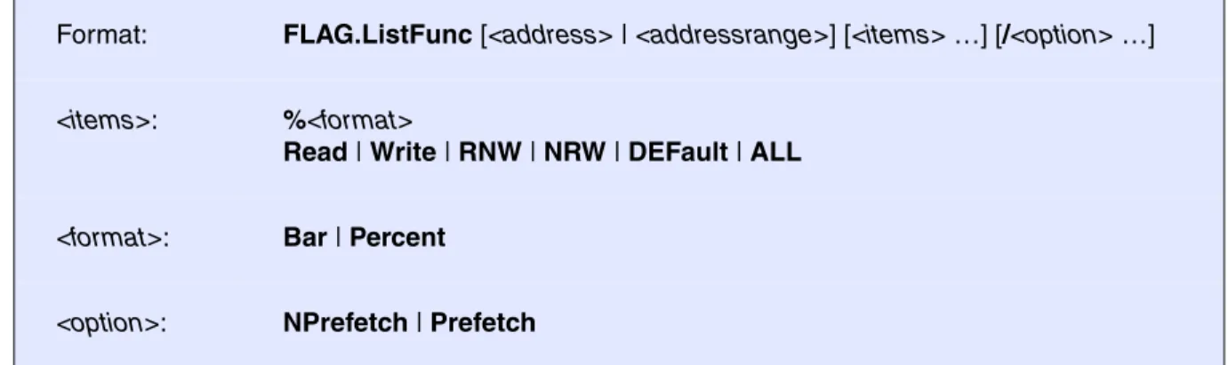
Format: FLAG.ListFunc [<address> | <addressrange>] [<items> …] [/<option> …]
<items>: %<format>
Read | Write | RNW | NRW | DEFault | ALL
<format>: Bar | Percent
<option>: NPrefetch | Prefetch
Read Generates a field output with consideration of the read flag information only.
Write Generates a field output with consideration of the write flag information only.
RNW Generates a field output for the supervised address range where the read-only condition is fulfilled.
NRW Generates a field output over the write-only information.
DEFault The defined default fields will be shown. The default is the 4 field types in graphical format and then in percent format. This configuration could be changed with the command SETUP.FLIST.
ALL All possible fields in all formats will be shown.
Bar Switches the output format to graphical value display. All following items will be displayed in this format. Bar is the default output format.
Percent Switches the output format to percent value display.
NPrefetch CPU accesses, which overlap the previous or next function (prefetch, cache or burst), are not displayed. The prefetch distance differs on the CPU type.
Is also default option.
Prefetch CPU accesses, which overlap the previous or next function (prefetch, cache or burst), are displayed. The prefetch distance differs on the CPU type.
The command SETUP.FLIST defines the default output of the flag list symbol commands.
Code-Coverage of CPU accesses, which overlap the previous or next function (prefetch, cache or burst), are not displayed in this example.
E::w.flag.lf
symbolname read write read only write only
\\MCC\mcc\func0 \\MCC\mcc\func1 \MCC\mcc\func1g \\MCC\mcc\func2 \\MCC\mcc\func3 \\MCC\mcc\func4
\\MCC\mcc\func5 function prefetched
\\MCC\mcc\func6 function fully executed
\\MCC\mcc\func7 \\MCC\mcc\func8 \\MCC\mcc\func9 \MCC\mcc\func10
\MCC\mcc\func11 function partly executed
MCC\mcc\func11a function not accessed
\MCC\mcc\func12 \MCC\mcc\func13
E::w.flag.lf /np
symbolname read write read only write only
\\MCC\mcc\func0 - function to short for analysis
\\MCC\mcc\func1 \MCC\mcc\func1g
\\MCC\mcc\func2 function code modified !!!
\\MCC\mcc\func3 \\MCC\mcc\func4
\\MCC\mcc\func5 function not accessed
\\MCC\mcc\func6
\\MCC\mcc\func7 function fully executed
\\MCC\mcc\func8 \\MCC\mcc\func9 \MCC\mcc\func10 \MCC\mcc\func11 MCC\mcc\func11a \MCC\mcc\func12 \MCC\mcc\func13
More detailed information is generated by a short click in the data section of the window.
See also
■ FLAG.state
▲ ’FLAG System’ in ’ICE User’s Guide’
E::w.d.l SD:5E72--0005F27 /m rf wrCBAWRSHP addr/line source
r H 401 switch ( x ) { case 1: H 404 x = x+1; H 405 x = x*2; H 406 return x*x; case 2: H 408 return x+x; case 3: H 410 return x-x; case 4: r H 412 x = x+1; r H 413 x = x*2; r H 414 return x*x; case 5: break; case 6: H 418 return x+x; default: break;
FIRE / ICE only
FLAG.ListModul
Code-coverage modules
Graphic and numeric display of the code coverage of the modules. More detailed information is generated by a short click in the data section of the window.
Format: FLAG.ListModul [<address> | <addressrange>] [<items> …] [/<option> …]
<items>: %<format>
Read | Write | RNW | NRW | DEFault | ALL
<format>: Bar | Percent
<option>: NPrefetch | Prefetch
Read Generates a field output with consideration of the read flag information only.
Write Generates a field output with consideration of the write flag information only.
RNW Generates a field output for the supervised address range where the read-only condition is fulfilled.
NRW Generates a field output over the write-only information.
DEFault The defined default fields will be shown. The default is the 4 field types in graphical format and then in percent format. This configuration could be changed with the command SETUP.FLIST.
ALL All possible fields in all formats will be shown.
Bar Switches the output format to graphical value display. All following items will be displayed in this format. Bar is the default output format.
Percent Switches the output format to percent value display.
NPrefetch CPU accesses, which overlap the previous or next function (prefetch, cache or burst), are not displayed. The prefetch distance differs on the CPU type.
Is also default option.
Prefetch CPU accesses, which overlap the previous or next function (prefetch, cache or burst), are displayed. The prefetch distance differs on the CPU type.
The command SETUP.FLIST defines the default output of the flag list symbol commands.
See also
■ FLAG.state
▲ ’FLAG System’ in ’ICE User’s Guide’
E::w.flag.lm
symbolname read write read only write only
\\MCC\entry \\MCC\mcc \\MCC\ADD \\MCC\LMUL \\MCC\FPK \\MCC\MEMSET \\MCC\csys \\MCC\outchr \\MCC\op_dadd \\MCC\op_dmul \\MCC\op_dtof \\MCC\op_fadd \\MCC\op_ftod \\MCC\dadd \\MCC\dpk \\MCC\ipk
FIRE / ICE only
FLAG.ListVar
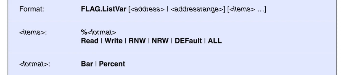
Code-coverage variables
Graphic and numeric display of the code coverage of HLL-variables.
Format: FLAG.ListVar [<address> | <addressrange>] [<items> …]
<items>: %<format>
Read | Write | RNW | NRW | DEFault | ALL
<format>: Bar | Percent
Read Generates a field output with consideration of the read flag information only. Write Generates a field output with consideration of the write flag information only. RNW Generates a field output for the supervised address range where the
read-only condition is fulfilled.
NRW Generates a field output over the write-only information.
DEFault The defined default fields will be shown. The default is the 4 field types in graphical format and then in percent format. This configuration could be changed with the command SETUP.FLIST.
ALL All possible fields in all formats will be shown.
Bar Switches the output format to graphical value display. All following items will be displayed in this format. Bar is the default output format.
Percent Switches the output format to percent value display.
NPrefetch CPU accesses, which overlap the previous or next function (prefetch, cache or burst), are not displayed. The prefetch distance differs on the CPU type. Prefetch CPU accesses, which overlap the previous or next function (prefetch,
cache or burst), are displayed. The prefetch distance differs on the CPU type.
The command SETUP.FLIST defines the default output of the flag list symbol commands.
More detailed information is generated when a short click in the data section of the window was done:
See also
■ FLAG.state
▲ ’FLAG System’ in ’ICE User’s Guide’
E::w.flag.lv
symbolname read write read only write only
\\MCC\vppulong
\\MCC\ast fully used data set
\\MCC\vbfield data part.
\\MCC\vshort not used
\\MCC\vdarray
\\MCC\def uninitialized data set
\\MCC\funcptr \\MCC\vpuint
E::w.d.p %var v.range(vbfield) /m rf
wrCBAWRSHP address data value symbol
wr SD:002554 FF vbfield.a / .b / .c / .d \\MCC\vbf wr SD:002555 FF vbfield.d / .e \\MCC\vbfield+1 wr SD:002556 F8 vbfield.e \\MCC\vbfield+2 wr SD:002557 00 vbfield \\MCC\vbfield+3 wr SD:002558 FF vbfield.f \\MCC\vbfield+4 wr SD:002559 FF vbfield.f / .g \\MCC\vbfield+5
wr SD:00255A FF vbfield.h \\MCC\vbfield+6
wr SD:00255B FF vbfield.h / .i \\MCC\vbfield+7
w SD:00255C FF vbfield.j \\MCC\vbfield+8
w SD:00255D FF vbfield.j \\MCC\vbfield+9
wr SD:00255E E0 vbfield.k / .l \\MCC\vbfield+0A
SD:00255F 00 vbfield \\MCC\vbfield+0B w SD:002560 FF vbfield.m \\MCC\vbfield+0C w SD:002561 FF vbfield.m \\MCC\vbfield+0D SD:002562 00 \\MCC\vbfield+0E SD:002563 00 \\MCC\vbfield+0F w SD:002564 FF vbfield.n = -1 \\MCC\vbfield+10 w SD:002565 FF \\MCC\vbfield+11 w SD:002566 FF \\MCC\vbfield+12
ICE only
FLAG.OFF
Switch-off flag system
The flag system would be switched off. The program activity doesn't influence the flag information. This command is not possible on real-time emulation.
See also
■ FLAG.state
▲ ’FLAG System’ in ’ICE User’s Guide’
ICE only
FLAG.ON
Switch-on flag system
The flag system would be switched on. Every program and data cycle sets the corresponding flag bit. This command is blocked if real-time emulation is running.
See also
■ FLAG.state
▲ ’FLAG System’ in ’ICE User’s Guide’
FIRE / ICE only
FLAG.RESet
Reset
The whole flag memory will be deleted and released (Unmapped).
See also
■ FLAG.state
Format: FLAG.OFF
Format: FLAG.ON
FIRE / ICE only
FLAG.Set
Set
This command is used to manually set flags before starting real-time emulation. Flag setting is needed to prevent read-before-write triggering on code and initialized data areas. See FLAG.SetSec. In EPROM based embedded controller systems the write flags should be set in the whole EPROM area (To detect malfunction set the write breakpoint too and protect against write).
Map
This option forces mapping of flag memory if necessary.
See also
■ FLAG.state
▲ ’FLAG System’ in ’ICE User’s Guide’
ICE only
FLAG.SetSec
Mark sections
If the object files loaded has correct information about initialized data and code areas, the presetting of the write flag should be done by this command instead of FLAG.Set. Presetting of the write flag prevents from read-before-write (RBW) triggering on code or initialized data access.
See also
■ FLAG.state
Format: FLAG.Set <address> | <addressrange> [/<option> …]
<option>: Read Write Map
flag.s 0x0--0x0ffff /w ; set write flags
ICE only
FLAG.state
State
The state of the flag system is shown. The commands FLAG.Init and FLAG.RESet are executable by mouse-clicking.
See also
■ FLAG.Delete ■ FLAG.Init ■ FLAG.List ■ FLAG.ListFunc ■ FLAG.ListModul ■ FLAG.ListVar ■ FLAG.OFF ■ FLAG.ON ■ FLAG.RESet ■ FLAG.Set ■ FLAG.SetSec
▲ ’FLAG System’ in ’ICE User’s Guide’ Format: FLAG.state
E::w.flag
state commands
OFF Init
FLASH
External FLASH memories and on-chip FLASH memories of microcontrollers can be programmed and erased by the FLASH command group.
An up-to date list of all supported FLASHs you will find at the LAUTERBACH home page under: http://www.lauterbach.com/ylist.html. The list is also available under “List of Supported FLASH Devices” (flashlist.pdf).
For further information please refer to “Onchip/NOR FLASH Programming User’s Guide” (norflash.pdf). The FLASH.Create command allows to define the layout of the FLASH memories on the target. After activating the programming option any memory modification command of TRACE32 will issue a FLASH programming sequence for the devices. Parallel programming of multiple FLASH devices is supported. The programming can be done in two different modes:
• TRACE32 software based
• target controlled (an extra FLASH programming routine is used)
The TRACE32 software based programming needs no programming algorithm running on the target and no target RAM, but is slow (typical about 1 to 5 KByte/s). An exception are buffered FLASH chips (like Intel FlashFile devices) which can be programmed at rates of more than 100 KByte/s.
Target controlled FLASH algorithms are called by TRACE32 with appropriate parameters to program a memory. The advantage of this method is the higher programming speed and more flexibility in the implementation of the programming algorithm.
LAUTERBACH provides ready to run binary files for target controlled FLASH programming. These files are available for most common architectures on the TRACE32 software CD under:
~~\demo\<cpu>\flash
The FLASH algorithms are organized by <bus_width>. The name of the FLASH algorithm corresponds to the <family_code>. To get the <family_code> refer to the FLASH.Create command or to the LAUTERBACH home page under http://www.lauterbach.com/ylist.html.
E.g. the algorithm to program a Am29LV640 at a 16 bit bus with an ARM core working in little endian mode can be found under ~~\demo\arm\flash\word\am29lv100.bin
In production environments, it is recommended to use target controlled FLASH programming and to load the FLASH data in binary format (Data.LOAD.Binary) to get the highest possible programming speed.
See also
■ FLASH.AUTO ■ FLASH.BSDLaccess ■ FLASH.CFI ■ FLASH.CHANGETYPE ■ FLASH.CLocK ■ FLASH.Create ■ FLASH.CreateALIAS ■ FLASH.Delete ■ FLASH.Erase ■ FLASH.List ■ FLASH.LOCK ■ FLASH.MultiProgram ■ FLASH.OFFSET ■ FLASH.Program ■ FLASH.ReProgram ■ FLASH.RESet ■ FLASH.state ■ FLASH.TARGET ■ FLASH.TARGET2 ■ FLASH.UNLOCK ■ FLASH.UNSECUREerase
FLASH.AUTO
Auto programming of FLASH
Activates the auto programming mode for the selected FLASH memory unit or address range or for all defined devices.
The auto programming mode can be used: • to patch code in FLASH.
• to set software breakpoints into FLASH.
Format: FLASH.AUTO [<unit> | <address_range> | ALL | off | CANCEL |
/CENSORSHIP]
<unit> Activate the auto programming mode for all sectors of the specified unit. ALL Activate the auto programming mode for all FLASH sectors.
off With parameter “off” or without argument the auto programming mode is terminated. Terminating the auto programming mode lets you program only the modified sectors.
CANCEL Abort without programming pending changes.
CENSORSHIP CPU specific option: Allows you to program the range where the FLASH security bytes are located.
NOTE: The FLASH.AUTO off and FLASH.ReProgram off commands automatically erase the modified sectors before writing them.
• Consequently, do not use FLASH.Erase when using the auto or reprog programming mode.
• If you do, you will lose the advantage of reprogramming only modified sectors, which will result in a loss of performance.
See also
■ FLASH.state
▲ ’Programming Commands’ in ’Onchip/NOR FLASH Programming User’s Guide’
FLASH.BSDLaccess
Enables FLASH access via boundary scan
Enables or disables FLASH memory access via boundary scan. The boundary scan chain must be configured with BSDL.FLASH.IFDefine and BSDL.FLASH.IFMap.
See also
■ FLASH.state
▲ ’FLASH Programming via Boundary Scan’ in ’Onchip/NOR FLASH Programming User’s Guide’ ; (--)
FLASH.AUTO ALL
Data.LOAD.Binary data.bin FLASH.AUTO off
Data.LOAD.Binary data.bin /DIFF
IF FOUND()
PRINT "Not ok!" ELSE
PRINT "FLASH ok!"
; No FLASH.Erase!
; Activate all FLASHs for programming ; load binary file
; Erase and program all modified ; sectors
; compare the contents of the FLASH ; with the file contents
; FOUND() returns TRUE if a ; difference was found
FLASH.CFI
Generate FLASH declaration by CFI
Generate FLASH declaration by using the CFI information stored in an off-chip FLASH device.
CFI (Common FLASH memory Interface) is an open standard, that specifies how FLASH identification information can be provided by FLASH devices. The identification information includes the memory size, block configuration, voltage and timing information etc.
Without any parameters a CFI dialog is opened.
Format 1
If Format 1 is used, a FLASH declaration for TRACE32 tool based FLASH programming is generated. Format 1: FLASH.CFI [[<unit_number>] <address> | <range> <bus_width>]
Format 2: FLASH.CFI [<unit_number>] <address> | <range> <bus_width> /TARGET \ <code_address> <data_address> <buffer_size> [/DualPort]
Format 3: FLASH.CFI [<unit_number>] <address> | <range> <bus_width> /TARGET2 \ <code_address> <data_address> <buffer_size> [/DualPort]
<bus_width> Byte | Word | Long | Quad
DualPort Dual-port can be used for target controlled FLASH programming only. For an explanation of the DualPort option, see FLASH.TARGET.
FLASH.RESet ; reset all FLASH declarations FLASH.CFI 0xc0000000 Long ; perform FLASH declaration by CFI FLASH.List ; display the FLASH declaration
AREA.view ; display the monitoring of the TRACE32 ; FLASH declaration commands
If several FLASH devices of the same type are used in serial, a FLASH.CFI for each FLASH device has to be used.
Format 2
If Format 2 is used, a FLASH declaration for target controlled FLASH programming is generated. FLASH.RESet ; reset all FLASH declarations
FLASH.CFI 0xc0000000 Long ; perform FLASH declaration by CFI FLASH.CFI 0xc2000000 Long ; perform FLASH declaration by CFI FLASH.List ; display the FLASH declaration
AREA.view ; display the monitoring of the TRACE32 ; FLASH declaration commands
; reset all FLASH declarations
FLASH.RESet
; FLASH.CFI <addr> <bus_width> /TARGET <code_address> <data_address> ; <buffer_size>
FLASH.CFI 0xc0000000 Long /TARGET 0x1000 0x2000 0x1000
; display flash programming dialog to check settings
FLASH.state
; display the FLASH declaration
FLASH.List
; display the monitoring of the TRACE32 FLASH declaration commands
Format 3
If Format 3 is used, a second FLASH declaration for target controlled FLASH programming is generated. This is needed for example to program processor internal and processor external NOR flash or HyperFlash together.
…
; script to set up onchip flash configuration
DO ~~/demo/tricore/flash/tc29x.cmm CPU=TC298TF PREPAREONLY DUALPORT=1
; configure external bus interface
…
; perform flash declaration for external NOR flash by CFI
FLASH.CFI 0xA4000000 Long /TARGET2 0xC0000000 0xD0000000 0x2000 /DUALPORT
; check configuration
FLASH.state FLASH.List
See also
■ FLASH.List ■ FLASH.state ■ FLASH.TARGET ■ FLASH.TARGET2 ❏ FLASH.CFI.SIZE()
▲ ’Standard Approach’ in ’Onchip/NOR FLASH Programming User’s Guide’ ▲ ’Release Information’ in ’Release History’
FLASH.CHANGETYPE
Changes the FLASH type
Changes the FLASH type (FLASH Family Code) for the specified range. All other options remain unchanged.
See also
■ FLASH.state
▲ ’Special Features for Onchip FLASHs’ in ’Onchip/NOR FLASH Programming User’s Guide’ ▲ ’Release Information’ in ’Release History’
Format: FLASH.CHANGETYPE <unit> <address_range> ALL | off
<unit> Change the FLASH type of the specified unit. ALL Changes the FLASH type of all FLASH sectors.
off (no effect)
;For the specified address range, change current type to type 'TARGET' FLASH.CHANGETYPE 0xA0018000--0xA001BFFF TARGET
FLASH.CLocK
Setup input clock for processor internal flash
The command is used to set up the FLASH module input clock for processor internal flash (target-controlled on-chip FLASH programming only).
See also
■ FLASH.state ❏ FLASH.CLocK.Frequency() Format: FLASH.CLocK <freq> | AUTO
FLASH.CLocK AUTO ; the FLASH programming algorithm measures ; the input clock before programming or ; erasing the FLASH
FLASH.Create
Define FLASH
Declaration of FLASH memories. Internal FLASH memories:
• are defined automatically. The address ranges of internal FLASH memory will be calculated when executing a FLASH.Erase or FLASH.Program command.
• have to be defined by the user. Ready-to-run batch scripts are available on the TRACE32 software CD in the directory files\demo\<cpu>\flash. The name of the batch script corresponds to the processor name.
If the FLASH has sectors of different size (boot block devices) one FLASH.Create command has to be entered for each sector size.
Format: FLASH.Create <unit_number> <physical_range> <sector_size> <family_code> <bus_width>
<family_ code>:
I28F001B | I28F200B | … | TARGET [/<option>] | EEPROM | NOP [/<option>]
<bus_width>: Byte | Word | Long | Quad
<option>: AutoInc | EraseALIAS | BootModeHeaDer | KEEP <address_range> | OTP | INFO <string>
A <unit_number> has to be declared for each device. If the processor has on-chip FLASH that is defined automatically by TRACE32, the unit numbers 1 … n are already in use for the on-chip FLASH. Please use the
FLASH.List command to check the next free unit number.
<sector_size> If no <sector_size> is specified then one sector occupying the full <physical_range> will be assumed.
<family_code> The family_code determines the programming algorithm. The FLASH types and the corresponding family_codes are listed under “List of Supported FLASH Devices” (flashlist.pdf).
<bus_width> The bus_width parameter defines the external data bus size (8-bit, 16-bit, 32-bit, 64-bit). Default: 8-bit. If the data bus size is wider than the bus size of the FLASH device, it will be assumed that FLASH devices of the same type are in parallel.
AutoInc Increments the FLASH.CREATE extra argument for every created sector by 1. See Example.
The AutoInc option is only available for TARGET and NOP and a few other FLASH family codes.
EraseALIAS <address_range>
The EraseALIAS option allows you to apply the commands
FLASH.Auto.off and FLASH.ReProgram.off to non-contiguous physical sectors.
The EraseALIAS option is, for example, used for a processor-internal FLASH with visible ECC sectors.
KEEP
<address_range>
Does not delete the specified address range when the commands FLASH.Erase and FLASH.ReProgram are executed. See Example. But, after the FLASH.ReProgram command has been executed, the specified address range can be overwritten.
BootModeHeaDer <address_range>
Only available for the TriCore debugger. See Example.
Does not delete the TriCore boot mode header when the commands FLASH.Erase and FLASH.ReProgram are executed.
But, after the FLASH.ReProgram command has been executed, the TriCore boot mode header can be overwritten.
OTP States in a declaration that the specified range is an OTP sector (One Time Programmable). See Example.
All regular FLASH erase and FLASH programming commands have no effect on the OTP sector. In the FLASH.List window, the state column displays “nop” for this OTP sector.
To activate the FLASH programming mode for an OTP sector, use the FLASH.Program ... /OTP command. In the FLASH.List window, the state column displays “otp” for this OTP sector.
INFO <string> Adds a user-defined comment to the extra column of the FLASH.List window (max. length 64 characters). See Example.
Example:
Definition for an Am29LV640 in 16 bit mode on a 16 bit bus. The FLASH provides 128 sectors each with 64 KByte:
Example:
Definition for 2 Intel 28F128J3 in 16 bit mode, 2 FLASHs in parallel on a 32 bit bus. Each FLASH provides 128 sectors with 128 KByte. Since the FLASHs are in parallel the sector size used with the FLASH.Create command is 2 x 128 KByte:
Example:
Definition for an Am29DL322DB in 8 bit mode on a 8 bit bus (FLASH sectors of different size - bottom boot block device). The 8 boot blocks have a size of 8 KByte, the 63 main blocks have a size of 64 KBytes:
You will find an up-to-date list of all supported FLASHs at the LAUTERBACH website under:
http://www.lauterbach.com/ylist.html. The list is also available under “List of Supported FLASH Devices” (flashlist.pdf).
The family_code TARGET must be selected if target controlled FLASH programming is used. The definitions for target based FLASH programming are done via the FLASH.Target command.
EEPROM can be used to declare an EEPROM area. When activated write accesses result in EEPROM programming sequences. This is useful if both FLASH and EEPROM areas are used by the download file. If no data accesses are allowed to a specific memory area, the option NOP can be used, to prevent any access when data transfer commands are used.
Compatible types are supported even if they are not explicitly listed. (Please note that not all FLASH types have been tested in all configurations).
It is recommended to use Long or Word option for load or memory copy command, corresponding to the bus_width defined with the FLASH.Create command.
On some ATMEL flash types the data written must be aligned to the flash page size. Use binary file format or copy from virtual memory if possible (refer to Data.Load <file> /VM for more information). TRACE32 software based programming is not working on all FLASHs.
FLASH.RESet
FLASH.Create 1. 0x0--0x7FFFFF 0x10000 AM29LV100 Word
FLASH.RESet
FLASH.Create 1. 0x0--0x1FFFFFF 0x40000 I28F200J3 Long
FLASH.RESet
FLASH.Create 1. 0x0--0xFFFF 0x2000 AM29LV100B Byte
Example for /AutoInc, /KEEP, /OTP, and /INFO
Example for /BootModeHeaDer
The BootModeHeaDer option is only available for TriCore. Example for a TriCore internal FLASH:
See also
■ FLASH.state
▲ ’FLASH Declaration in Detail’ in ’Onchip/NOR FLASH Programming User’s Guide’ ▲ ’Release Information’ in ’Release History’
FLASH.RESet
FLASH.Create 0x1000000--0x100FFFF 0x4000 TARGET Long 0. \
/AutoInc /KEEP 0x1003FFC--0x1003FFF FLASH.Create 0x0400000--0x0403FFF 0x4000 TARGET Long 0x500 \
/OTP /INFO "UTEST sector"
FLASH.List
FLASH.Create 1. 0xA0000000--0xA0003FFF TARGET Long \
/BootModeHeaDer 0xA0000000--0xA000001F A user-defined comment is added by /INFO
FLASH.CreateALIAS
Create address alias
All FLASH write cycles to <address_range> are performed to the address range starting with <alias_address>.
This command is useful when the on-chip FLASH is mapped to different addresses, for example: • At address 0x0C000000--0x0C01FFFF for uncached accesses
• At address 0x08000000--0x0801FFFFF for cached accesses
Due to this, a compiler may generate bootcode for the uncached address range and application code for the cached address range. This situation complicates the programming of the on-chip FLASH. With the command FLASH.CreateALIAS flash programming is only executed in the uncached address range. The command FLASH.CreateALIAS might also be useful for mirrored FLASH address ranges.
Format: FLASH.CreateALIAS <address_range> <alias_address>
;reset FLASH definition table FLASH.RESet
;declare FLASH sectors
FLASH.Create 1. 0x0C000000--0x0C00FFFF 0x4000 TARGET Long FLASH.Create 2. 0x0C010000--0x0C01FFFF 0x4000 TARGET Long
;all FLASH write cycles to the address range 0x08000000--0x0801FFFF ;(cached) are actually performed to the address range
;0x0C000000--0x0C01FFFF (not cached)
FLASH.CreateALIAS 0x08000000--0x0801FFFF 0x0C000000
;define the target controlled FLASH algorithm FLASH.TARGET 0x1FFFE000 0x20000000 0x1000 \
~~/demo/arm/flash/long/xmc4000.bin ;open the window
The alias is also displayed in the listing of the FLASH declarations, see FLASH.List window:
See also
■ FLASH.state
▲ ’Special Features for Onchip FLASHs’ in ’Onchip/NOR FLASH Programming User’s Guide’
FLASH.Delete
Delete entry in FLASH definition table
The specified FLASH entry is removed from the definition table. Use the command FLASH.RESet to clear the whole list and the entire FLASH target configuration.
See also
A Cached address range.
B Destination address for uncached memory.
Format: FLASH.Delete <unit> | <address_range> | ALL | off
<unit> Delete the specified unit.
ALL Deletes all FLASH entries from the definition table.
off (no effect)
FLASH.Delete 2. ; delete unit 2 from the definition table. ; A unit can consist of multiple flash ; sectors.
FLASH.Delete 0x2000--0xffff ; delete the specified flash sectors. ; from the definition table.
FLASH.Delete ALL ; delete all flash sectors from the ; definition table.
A
FLASH.Erase
Erase FLASH
Erases the selected FLASH memory unit or address range or all defined devices.
See also
■ FLASH.state
▲ ’TRACE32 Tool-based Programming’ in ’Tips to Solve NOR FLASH Programming Problems’ ▲ ’Programming Commands’ in ’Onchip/NOR FLASH Programming User’s Guide’
Format: FLASH.Erase <unit> | <address_range> | ALL | off
<unit> Erase the specified unit.
ALL Erase all FLASH sectors of a FLASH memory.
off (no effect)
FLASH.Erase 1. ; erase unit 1 from the FLASH memory. FLASH.Erase 0x0--0x1FFFF ; erase the specified FLASH sectors
; from the FLASH memory. FLASH.Erase ALL ; erase all flash sectors
FLASH.List
Display FLASH definition table
Displays the address range, family code, bus width, state (if programming or auto is activated), and the unit number of defined FLASH memories. For a description of the columns in the FLASH.List window, see table below.
Description of Columns in the FLASH.List Window
• address: Address range of a sector.
• type: FLASH family code. An ALIAS entry is created with FLASH.CreateALIAS. • width: Data bus width (Byte, Word, Long, Quad).
• state
- program: FLASH programming for the selected sector is activated by FLASH.Program. - reprog: FLASH programming for the selected sector is activated by FLASH.ReProgram. - pending: The contents in the virtual host memory differs from the real FLASH contents.
FLASH will be programmed by FLASH.AUTO.off or FLASH.ReProgram.off.
- nop: Sectors that are not affected by FLASH.Program, FLASH.AUTO, or FLASH.ReProgram. - otp: OTP sector programming is enabled by FLASH.Program... /OTP.
• unit: A unit consists of multiple sectors. Each row stands for one sector. Related sectors have the same unit number.
• extra: Displays the extra value and the options created with FLASH.Create, including user-defined comments.
See also
■ FLASH.CFI ■ FLASH.state ❏ FLASH.List.STATE.PENDING() ▲ ’FLASH Functions’ in ’General Functions’
Format: FLASH.List
Unit 1. consists of multiple sectors. Each row stands
FLASH.LOCK
Lock FLASH
Lock the selected sectors of a FLASH device.
See also
■ FLASH.state ■ FLASH.UNLOCK
▲ ’TRACE32 Tool-based Programming’ in ’Tips to Solve NOR FLASH Programming Problems’ Format: FLASH.LOCK <unit> | <address_range> | ALL | off
<unit> Lock the specified unit. ALL Lock all FLASH sectors.
off (no effect)
FLASH.LOCK 1. ; lock unit 1. in the FLASH memory. FLASH.LOCK 0x0--0x1FFFF ; lock the specified range
; in the FLASH memory. FLASH.LOCK ALL ; lock all FLASH sectors