Implementation of
JPEG 2000 Using Spiht Algorithm
K. RameshbabuProfessor & Head,
Department of Electronics & Communication, HITAM, Hyderabad
Email: [email protected]
S. Janardhana Rao Professor,
Electronics & Communication, HITAM, Hyderabad Email: : [email protected]
Abstract — The JPEG 2000 standard for still image compression provides rich set of features, including lossless and lossy compression, region of interest coding, and progressive transmission. JPEG 2000 provides lower bit rates at the same rate distortion and subjective quality levels as the older JPEG standards. The features were realized using two techniques namely the Discrete Wavelet Transform (DWT), and Hardware architecture for the proposed process was developed, realized in VHDL, and synthesized for implementation on FPGA XILINX Spartan 3E.
Key Words — Lifting Scheme, FPGA, JPEG 2000 image compression, SPIHT Algorithm, VHDL.
I. I
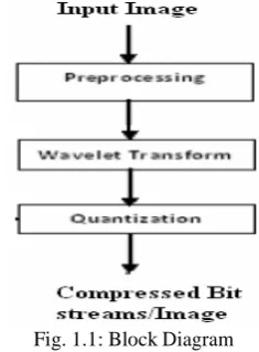
NTRODUCTIONThe JPEG 2000 standard for still image compression provides rich set of features, including lossless and lossy compression, region of interest coding, and progressive transmission. JPEG2000 provides lower bit rates at the same rate distortion and subjective quality levels as the older JPEG standards. There are several stages involved in the compression of an image. In preprocessing stage, the encoder transforms the input sample data to a nominal dynamic range so that it is approximately centered about zero. If the input sample data is signed, then assume they are centered at zero. JPEG2000 optionally allows for an inter-component to be applied to the image after it has been level-shifted. This transform helps decor relate the separate components for multi-component images. Then, a discrete wavelet transform on each tile to decompose it into a number of wavelet sub bands at different levels and resolutions. In JPEG2000, the lifting-based DWT implementation is applied. DWT is an important process to generate bit streams with resolutions, and decompose the spatial correlation. The output of this stage is a set of transformed coefficients. The wavelet coefficients in each sub band are scalar quantized using SPIHT concept. A purpose for quantization is that fewer bits will be used to encode the transformed coefficients.
A majority of today’s Internet bandwidth is estimated to be used for images and video. Recent multimedia applications for handheld and portable devices place a limit on the available wireless bandwidth. The bandwidth is limited even with new connection standards. JPEG image compression that is in widespread use today took several years for it to be perfected. Wavelet based techniques such as JPEG2000 for image compression has a lot more to offer than conventional methods in terms of compression ratio. Currently wavelet implementations are still under development lifecycle and are being perfected.
Flexible energy-efficient hardware implementations that can handle multimedia functions such as image processing, coding and decoding are critical, especially in hand-held portable multimedia wireless devices.
Fig. 1.1: Block Diagram
II. F
UNDAMENTALS OFD
IGITALI
MAGEDigital image is defined as a two dimensional function f(x, y), where x and y are spatial (plane) coordinates, and the amplitude of f at any pair of coordinates (x, y) is called intensity or grey level of the image at that point. The field of digital image processing refers to processing digital images by means of a digital computer. The digital image is composed of a finite number of elements, each of which has a particular location and value. The elements are referred to as picture elements, image elements, pels, and pixels. Pixel is the term most widely used.
1.1 Image Compression
Digital Image compression addresses the problem of reducing the amount of data required to represent a digital image. The underlying basis of the reduction process is removal of redundant data. From the mathematical viewpoint, this amounts to transforming a 2D pixel array into a statically uncorrelated data set. The data redundancy is not an abstract concept but a mathematically quantifiable entity. If n1 and n2 denote the number of information-carrying units in two data sets that represent the same information, the relative data redundancy
R
D of the first data set (the one characterized by n1) can be1
defined as,
R
D=
1
−
C
Rn1
C
R =n2
In image compression, three basic data redundancies can be identified and exploited: Coding redundancy, interpixel redundancy, and phychovisal redundancy. Image compression is achieved when one or more of these redundancies are reduced or eliminated.
The image compression is mainly used for image transmission and storage. Image transmission applications are in broadcast television; remote sensing via satellite, aircraft, radar, or sonar; teleconferencing; computer communications; and facsimile transmission. Image storage is required most commonly for educational and business documents, medical images that arise in computer tomography (CT), magnetic resonance imaging (MRI) and digital radiology, motion pictures, satellite images, weather maps, geological surveys, and so on.
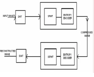
Fig. 2.1 Block Diagram
III. L
IFTINGS
CHEMEThe wavelet transform of image is implemented using the lifting scheme [3]. The lifting operation consists of three steps. First, the input signal x[n] is down sampled into the even position signal xe (n) and the odd position signal xo(n) , then modifying these values using alternating prediction and updating steps.
Fig 3.1 The Lifting Scheme.
IV. S
PHITA
LGORITHMEmbedded zero tree wavelet (EZW) coding, introduced by J. M. Shapiro, is a very effective and computationally simple technique for image compression. Here we offer an alternative explanation of the principles of its operation, so that the reasons for its excellent performance can be better understood. These principles are partial ordering by magnitude with a set partitioning sorting algorithm, ordered bit plane transmission, and exploitation of self-similarity across different scales of an image wavelet transform. Moreover, we present a new and different implementation based on set partitioning in hierarchical trees (SPIHT), which provides even better performance than our previously reported extension of EZW that surpassed the performance of the original EZW. The image coding results, calculated from actual file sizes and images reconstructed by the decoding algorithm, are either comparable to or surpass previous results obtained through much more sophisticated and computationally complex methods. In addition, the new coding and decoding procedures are extremely fast, and they can be made even faster, with only small loss in performance.
4.1. Progressive Image Transmission
After converting the image pixels into wavelet coefficient SPIHT [10] is applied. We assume, the original image is defined by a set of pixel values
p
i, j, where (i, j)x
e(n)
=
x[2n]
andx
o(n)
=
x[2n
+
1]
the pixel coordinates. The wavelet transform is actuallyA prediction step consists of predicting each odd sample as a linear combination of the even samples and subtracting it from the odd sample to form the prediction error.
oddj+1,i= oddj,i- P( evenj,i)
An update step consists of updating the even samples by adding them to a linear combination of the prediction error to form the updated sequence.
evenj+1,i= evenj,i+ U( oddj+1,i)
The prediction and update may be evaluated in several steps until the forward transform is completed. The block diagram of forward lifting and inverse lifting is shown in figure 3.1
done to the array given by,
c(i, j)
=
DWT{ p(i, j)}
.Where c (i, j) is the wavelet coefficients.
In SPIHT, initially, the decoder sets the reconstruction vector
c
)
to zero and updates its components according to the coded message. After receiving the value (approximate or exact) of some coefficients, the decoder can obtain a reconstructed image by taking inverse wavelet transform,p
ˆ
(i, j)
=
IDWT{c(i, j)}
called as“progressive transmission”.
2
1
N
2 DMSE( p−pˆ)= 1
N p−pˆ 2
=N1
∑∑
i j( pi, j−pˆi , j) the decoder is used to partition
T
m, into new subsetsT
m,l and the significance test is then applied to the new subsets. Where N is the number of image pixels.p
i , j is the This set division process continues until the magnitude testis done to all single coordinate significant subsets in order Original pixel value and
p
ˆ
i, j is the reconstructed pixelto identify each significant coefficient. value. Furthermore, we use the fact that the Euclidean
norm is invariant to the unitary transformation
To reduce the number of magnitude comparisons (message bits) we define a set partitioning rule that uses an expected ordering in the hierarchy defined by the subband
DMSE( p−pˆ)=DMSE(c−cˆ)=
∑∑
(ci , j−cˆi , j) i jpyramid. The objective is to create new partitions such that subsets expected to be insignificant contain a large
From the above the equation, it is clear that if the exact value of the transform coefficient
c
i , jis sent to the2
number of elements, and subsets expected to be significant contain only one element.
To make clear the relationship between magnitude comparisons and message bits, we use the function decoder, then the MSE decreases by
c
i , j/ N
. Thismeans that the coefficients with larger magnitude should
be transmitted first because they have a larger content of
S
n(T )
=
1;Max
{c
(i, j )∈Tmi, j
}
≥
2
ninformation. This is the progressive transmission method.
Extending this approach, we can see that the information 0; otherwise.
in the value of
c
i, j can also be ranked according to its to indicate the significance of a set of coordinatesT
. Tobinary representation, and the most significant bits should simplify the notation of single pixel sets, we write be transmitted first. This idea is used, for example, in the
bit-plane method for progressive transmission. Following,
S
n({(i, j)})
asS
n(i, j)
.we present a progressive transmission scheme that incorporates these two concepts: ordering the coefficients by magnitude and transmitting the most significant bits first. To simplify the exposition, we first assume that the ordering information is explicitly transmitted to the decoder. Later, we show a much more efficient method to code the ordering information.
4.2. Set Partitioning Sorting Algorithm
One of the main features of the proposed coding method is that the ordering data is not explicitly transmitted. Instead, it is based on the fact that the execution path of any algorithm is defined by the results of the comparisons on its branching points. So, if the encoder and decoder have the same sorting algorithm, then the decoder can duplicate the encoder’s execution path if it receives the results of the magnitude comparisons, and the ordering information can be recovered from the execution path.
One important fact used in the design of the sorting algorithm is that we do not need to sort all coefficients. Actually, we need an algorithm that simply selects the
4.3 Spatial Orientation Trees
A tree structure, called spatial orientation tree, naturally defines the spatial relationship on the hierarchical pyramid. Fig.5.4 shows how our spatial orientation tree is defined in a pyramid constructed with recursive four-subband splitting. Each node of the tree corresponds to a pixel and is identified by the pixel coordinate. Its direct descendants (offspring) correspond to the pixels of the same spatial orientation in the next finer level of the pyramid. The tree is defined in such a way that each node has either no offspring (the leaves) or four offspring, which always form a group of 2 x 2 adjacent pixels.
In Fig. 5.4, the arrows are oriented from the parent node to its four offspring. The pixels in the highest level of the pyramid are the tree roots and are also grouped in 2 x 2 adjacent pixels. However, their offspring branching rule is different, and in each group, one of them (indicated by the star in Fig. 5.4) has no descendants.
The following sets of coordinates are used to present the new coding method:
coefficients such that
2
n≤
c
i , j<
2
n+1, with nO (i, j): set of coordinates of all offspring of node (i, j); D (i, j ) : set of coordinates of all descendants of the node
decremented in each pass. Given n, if
c
i , j≥
2
n+1then H: set of coordinates of all spatial orientation tree roots(nodes in the highest pyramid level); we say that a coefficient is significant; otherwise it is
called insignificant. The sorting algorithm divides the set
L(i, j ) = D(i, j ) - O(i, j )
For instance, except at the highest and lowest pyramid of pixels into partitioning subsets
T
mmagnitude test
and performs the levels, we have:
O(i, j) = {(2i, 2j),(2i, 2j+1),(2i+1, 2j),(2i+1, 2j+1)} We use parts of the spatial orientation trees as the
Max
{ c(i, j )∈Tm
i, j}≥2 n
partitioning subsets in the sorting algorithm. The set partition rules are simply the following.
If the decoder receives a“no’’to that answer (the subset is insignificant), then it knows that all coefficients in
T
m, are insignificant. If the answer is “yes” (the subset is significant), then a certain rule shared by the encoder andI)The initial partition is formed with the sets ((i, j ) ) and D(i, j ), for all (i, j)∈H.
3)If L(i, j) is significant, then it is partitioned into the four sets D(k, I), with (k, I)∈O(i, j )
Fig 4.1 Examples of parent-offspring dependencies in the Spatial-orientation tree
4.4 Optimized Embedded Coding
A strict definition of the embedded coding scheme is: if two files produced by the encoder have size M and N bits, with M > N, then the file with size N is identical to the first N bits of the file with size M.
Let's see how this abstract definition is used in practice. Suppose you need to compress an image for three remote users. Each one have different needs of image reproduction quality, and you find that those qualities can be obtained with the image compressed to at least 8 Kb, 30 Kb, and 80 Kb, respectively. If you use a non-embedded encoder (like JPEG), to save in transmission costs (or time) you must prepare one file for each user. On the other hand, if you use an embedded encoder (like SPIHT) then you can compress the image to a single 80 Kb file, and then send the first 8 Kb of the file to the first user, the first 30 Kb to the second user, and the whole file to the third user.
Surprisingly, with SPIHT all three users would get (for the same file size) an image quality comparable or superior to the most sophisticated non-embedded encoders available today. SPIHT achieves this feat by optimizing the embedded coding process and always coding the most important information first
A. L
OSSLESSC
OMPRESSIONSPIHT codes the individual bits of the image wavelet transform coefficients following a bit-plane sequence. Thus, it is capable of recovering the image perfectly (every single bit of it) by coding all bits of the transform. However, the wavelet transform yields perfect reconstruction only if its numbers are stored as infinite-precision numbers. In practice it is frequently possible to recover the image perfectly using rounding after recovery, but this is not the most efficient approach.
A codec that uses this transformation to yield efficient progressive transmission up to lossless recovery is among the SPIHT .A surprising result obtained with this codec is that for lossless compression it is as efficient as the most effective lossless encoders (lossless JPEG is definitely not among them). In other words, the property that SPIHT yields progressive transmission with practically no penalty
in compression efficiency applies to lossless compression too.
A. Rate or Distortion Specification
Almost all image compression methods developed so far do not have precise rate control. For some methods you specify a target rate, and the program tries to give something that is not too far from what you wanted. For others you specify a "quality factor" and wait to see if the size of the file fits your needs.
The embedded property of SPIHT allows exact bit rate control, without any penalty in performance (no bits wasted with padding or whatever). The same property also allows exact mean squared-error (MSE) distortion control. Even though the MSE is not the best measure of image quality, it is far superior to other criteria used for quality specification.
B. encoding/decoding speed
A straightforward consequence of the compression simplicity is the greater coding/decoding speed. The SPIHT algorithm is nearly symmetric, i.e., the time to encode is nearly equal to the time to decode. (Complex compression algorithms tend to have encoding times much larger than the decoding times.)
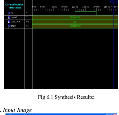
1.
Simulation ResultsFig 6.1 Synthesis Results:
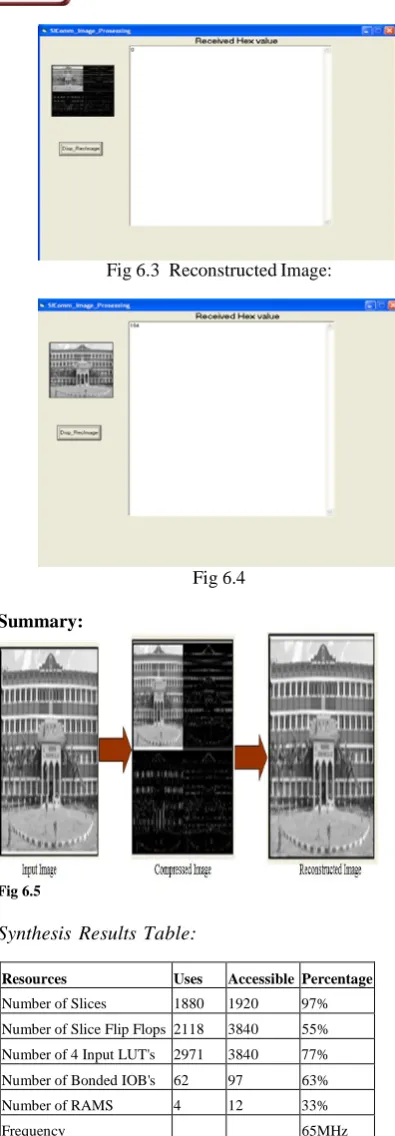
2. Input Image
operations per sample, leading to a reduced chip area and power consumption .it can be said that the original design criteria has been considered and an effective and feasible architecture has been designed.
R
EFERENCESSummary:
Fig 6.3 Reconstructed Image:
Fig 6.4
[1] Ajith Boopardikar, Wavelet Theory and Application,TMH [2] I.Daubechies W. Sweldens,“Factoring wavelet transforms into
lifting schemes,” J. Fourier Anal. Appl.,vol. 4, pp. 247–269, 1998.
[3] W. Sweldens, “The lifting scheme: A new philosophy in biorthogonal wavelet constructions,”in Proc. SPIE, vol. 2569, 1995, [3]
[4] JPEG2000 Committee Drafts[Online]. [5] Available:http://www.jpeg.org/CDs15444.htm
[6] JPEG2000 Verification Model 8.5 (Technical Description), Sept. 13,2000.
[7] K. Andra, C. Chakrabarti, and T. Acharya,“A VLSI architecture for lifting based wavelet transform,” inProc. IEEE Workshop SignlProces. Syst., Oct. 2000, pp70–79.
[8] Real-time image compression based on wavelet vector quantization, algorithm and VLSI architecture ,Hatami, S. Sharifi, S. Ahmadi, H. Kamarei, M. Dept. of Electr. & Comput. Eng., Univ. of Tehran, Iran; IEEE
Trans,May 2005.
[9] Fourier Analysis- http://www.sunlightd.com/Fourier/
[10] A VLSI Architecture for Lifting-Based Forward and Inverse Wavelet Transform
[11] Kishore Andra, Chaitali Chakrabarti, Member, IEEE, and Tinku Acharya, Senior Member, IEEE, IEEE Trans. on Signal
Processing, vol. 50,No.4, April 2002.
[12] K. K. Parhi and T. Nishitani,“VLSI architectures for discrete wavelet transforms,”IEEE Trans. VLSI Syst., vol. 1, pp. 191–
202, June 1993.
[13] M. Ferretti and D. Rizzo,“A parallel architecture for the 2-D discrete wavelet transform with integer lifting scheme,”J. VLSI Signal Processing, vol. 28, pp. 165–185, July 2001.
[14] Discrete Wavelet Transform
http://en.wikipedia.org/wiki/Discrete_wavelet_transform
A
UTHOR’
SP
ROFILEFig 6.5
Synthesis Results Table:
Resources Uses Accessible Percentage
Number of Slices 1880 1920 97% Number of Slice Flip Flops 2118 3840 55% Number of 4 Input LUT's 2971 3840 77% Number of Bonded IOB's 62 97 63%
Number of RAMS 4 12 33%
Frequency 65MHz
C
ONCLUSIONThe architecture has been implemented using VHDL; The VHDL description has been done at register level and is ready to become synthesized. The model has been verified with a set of text data. the derived architecture has many advantages especially the reduction in the number of
Dr. K.Ramesh Babu
S.Janardhana Rao
Professor ECE, Hyderabad Institute of Technology and Management, Hyderabad. He has AMIE ECE, Institute of Engineers Kolkata (2003), ALCCs Computer Science & Engineering from IETE New Delhi–(2009) & Master of Technology: Electronics & Communications Engineering–