16
Optimization the process parameter of FDM 3D
printer using Taguchi method for improving the
tensile strength
Mahesh Saini
M.Tech. Student, UIET MDU Rohtak
ABSTRACT
FDM is the three – dimensional or “ Additive Manufacturing ” process. FDM directly fabricated the 3D product from computer aided design ( CAD ) software. The quality of FDM manufacture 3D parts depend on the several process parameters like raster angle, layer thickness, temperature, infill density, shell thickness, air gap etc. among these parameters material, temperature and infill density most significant for improve the tensile strength of product. So this work focus on enhance the tensile strength FDM 3D printer manufacture product by optimizing the three parameters such as infill density, material and temperature at 3 level using Taguchi method. Acrylonitrile Butadiene styrene (ABS) material, Polyethylene Terephthalate Glycol (PETG) material and bi- material (combination of 50% ABS and 50% PETG ) material is used for fabricated the ASTM D638 type iv testing specimen. The variable parameter such as infill density, temperature and material density varies 30% to 50%, 2200c to 2600c and 1.04 kg/m3 to 1.23 kg/m3 respectively. The tensile strength of these specimen have been tested using UNITEK 94100 UTM machine. The five test have been performed on each specimen. We find the PEGT material at 40% infill density and 2400c having more strength that is 39.5 Mpa. Taguchi ‟s 33
design of experiment for orthogonal array L9 is used for optimization the parameters. Finally conclude the infill density is most influence factor for enhance the tensile strength instead temperature. Tensile strength increase with the infill density up to 40% beyond the this limit its decrease with increase the infill density.
INTRODUCTION
3D printing is discovered in1976. 3D printing is “Additive” manufacturing process. In which add the material layer by layer in prescribed manner until the part is complete. In which slice the part in CAD software and fed the material by extruded nozzle in layer by layer on the printer bed.
3D printing allows to manufactured the complicated moving and prototype parts [1]. The trend of new manufacturing technology improve and slowly change with the manual or conventional manufacturing [2]. FDM 3D modeling is the technology that use similar to manual or conventional injection moulding manufacturing process. The different thing in FDM, moulding is omitted in the process and flat surface is replaced on moulding which is made by glass or steel. In FDM technology molten polymer metal is extruded on flat bed by hot end nozzle in layer by layer manner according to programmeming of CAD software [3]. FDM is most versatile use in prototype technology to manufacture the complicated functional part in short time [4]. Generally it was used to plastic polymer prototype, tools and moving functional parts without geometrical intricate limitation [5].Many types of material are available for this manufacturing technology such as, acrylonitrile butadiene styrene (ABS), polycarbonate (PC), polylactic acid (PLA), Polyethylene Terephthalate Glycol (PETG) and PCABS blend.
17 sintering (SLS), stereo-lithography (SLA) and inkject moulding (IJM). These are technology are differ from each other in the way of layer deposition and in types of material use that can be fabricated in the manufacturing process safely. FDM is most versatile additive manufacturing process that provides functional parts and prototype in many thermoplastic polymer due to its capability to produce complicated geometrical parts neatly and safely with eco- friendly environment. FDM was invented by Stratasys Inc. in 1990s in USA [11-14].
METHODOLOGY A. Materials and Method:
The material is used in this study is acrylonitrile butadiene styrene (ABS), Polyethylene Terephthalate Glycol
(PETG) and combined or bi- material ( 50% of ABS + 50% of PETG) of 1.75mm diameter. In Bi-material specimen 50% layer makes by Acrylonitrile butadiene styrene (ABS) material and rest 50% layer makes by Polyethylene Terephthalate Glycol (PETG) material. ABS and PETG has several characteristics like it has low melting point which is 230 c and 250 c respectively so its require less printing temperature as well as it is less toxic compared with other thermoplastic.
We use the FDM ( Fused deposition modeling ) technology for prepare or slice the 3D part modeling. Our FDM printer model is Geeetech A30 having number of useful features such as automatic leveling, print resume availability and least movement of nozzle in Z direction is 0.005mm which is help in prepare accurate 3D complex geometric part. It has following featutes.
Table 1: FDM specification
Sr. no Features Value
1 Model Geeetech A30
2 Print Volume 320*320*420mm
3 Machine Dim 508*615.5*630.5mm
4 Precession 0.05-0.3mm
5 Speed 80-100 mm/s
6 Power 500w
7 Extruder Nozzle 1
8 Filament Size 1.75mm
9 Filament Type ABS, PLA,PETG etc.
10 Nozzle size 0.4mm
11 Processor Arduino processor
B. Specimen Preparation:
The research is start with 3D modeling to make a design by using solid modeling software CREO 4.0. In CREO 4.0 software we prepare the ASTM D638 specimen according the standards. After this we slice the 3D ASTM D638 specimen in CURO software. We slice the specimen on following parameters.
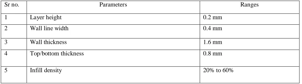
Table 2: parameters with range
Sr no. Parameters Ranges
1 Layer height 0.2 mm
2 Wall line width 0.4 mm
3 Wall thickness 1.6 mm
4 Top/bottom thickness 0.8 mm
18
6 Infill pattern Grid
7 Material diameter 1.75mm
8 Printing nozzle temperature 230 for ABS material
250 for PETG material
9 Bed temperature 80 degree
10 Printing speed 70 mm/s
11 Brim width 4.0 mm
12 Brim length 250 mm
We slice the specimen and vary the infill density such as 20%,30%,40%,50% and 60%, and another parameters keep remains constant. After creating the SLS file (G code file) of specimen at different infill density and another constant parameters then save in removable disk. Than insert the disk in processor ( Arduino processor ) which is read the programme of instruction and execute the instruction in mechanical action with the help of steeper motor, extruded nozzle etc. Then maintain the gap between printer bed and nozzle by manually or automatic leveling of flat bed, both of option available in 3D printer. Gap is maintained by Z direction movement of nozzle with the help of steeper motor. After accurate level of bed at every point than start the programme. Maintain the nozzle temperature and bed temperature according to material (for ABS nozzle temperature is 230 and for PETG is 250). Glue is used on the printer flat bed before the first layer come out from nozzle for stickiness of layer on flat bed. The FDM 3D printer, print the specimen layer by layer from bottom to top, according to programme of instruction (G Code file). After fulfill all the layer and programme has stop, remove the specimen from bed with the help of proper tool, then clean the flat bed for next specimen. All the process are apply on all specimen and we manufactured the 5 pieces of every material (ABS, PETG and combined) and infill density percentage like as 20% to 60% for taking the average reading of 5 pieces at testing time.
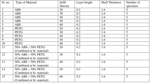
Table 3: of specimen with parameter variations
Sr. no Type of Material Infill
Density
Layer height Shell Thickness Number of specimen
1 ABS 20 0.2 1.6 5
2 ABS 30 0.2 1.6 5
3 ABS 40 0.2 1.6 5
4 ABS 50 0.2 1.6 5
5 ABS 60 0.2 1.6 5
6 PETG 20 0.2 1.6 5
7 PETG 30 0.2 1.6 5
8 PETG 40 0.2 1.6 5
9 PETG 50 0.2 1.6 5
10 PETG 60 0.2 1.6 5
11 50% ABS + 50% PETG
(Combined or bi- material)
20 0.2 1.6 5
12 50% ABS + 50% PETG
(Combined or bi- material)
30 0.2 1.6 5
13 50% ABS + 50% PETG
(Combined or bi- material)
40 0.2 1.6 5
14 50% ABS + 50% PETG
(Combined or bi- material)
50 0.2 1.6 5
15 50% ABS + 50% PETG
(Combined or bi- material)
60 0.2 1.6 5
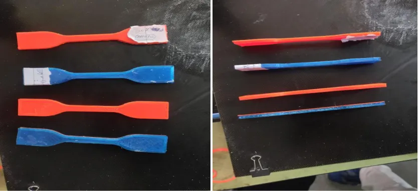
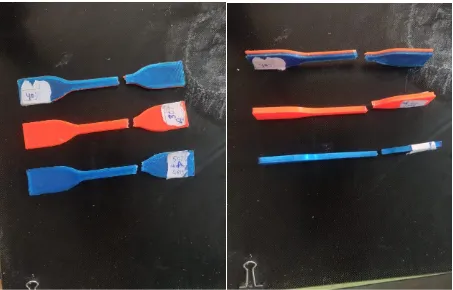
19 Fig.1: prepared specimens
C. Discussion:
Various process parameters of specimens:
Layer height (mm):
In the FDM additive manufacturing technology add the material layer by layer from bottom to top, the layer height play the vital role In variation in mechanical as well as physical properties. Layer height remain constant in the study.
Shell thickness (mm):
Thickness of outer shell of 3D part is known as shell thickness. It is use with the infill density which is improve the mechanical or physical properties. .
Infill Density (mm):
Infill density is directly represent the amount of material is fill in the part or product. It is show the the degree of solidness and is also related to the strength of part or product, manufactured by the 3D printing process. Infill pattern also affect the strength of part or product instead infill density kept remain constant at same weight of part or product.
20 Printing speed (mm/s):
Printing speed is the sense amount of filament in mm is moved per unit second. More of printing speed decrease the quality of print (rough surface finishing). Less printing speed increase the print time.
D. Manufacturing process: Modeling
3D modeling may be prepare in CAD (computer aided design ) software, by a 3D scanner, or by a photogrammetry software. 3d models which is prepare in CAD software result in minimize error and can be correct before the actual printing, allowing calibration in the design of the part before it is printed.
.
Fig.3: ASTM D638 IV EXPERIMENTAL ANALYSIS
After prepare the whole ASTM D 638 specimen by different material at different infill density we go for testing on UTM (universal testing machine) machine for test the tensile strength of each specimen.
Tensile test:
UTM ( universal testing machine ) is also known as universal tester, material test frame and material testing machine. In the beginning it is also known as Tensometer. It is used for specially compressive test and tensile test. The “ universal ” part of name is resonate because it can perform many tensile and compressive test on material, structure or frame and component.
Testing Process:
Firstly set the machine by removing the error like set the machine at zero load and set fix or movable crosshead at proper position. After that create the new file in computer and add the type of material of specimen, shape of specimen ( Round or Rectangular ), gauge length ( the length which is under study or observation ), nature of testing ( tensile or compressive ) and which graph is required. Then placed the specimen in machine between the extensometer by hold the specimen at equal distance from both side (or at gauge length ). Now start the testing by apply the increasing load on the specimen, extensometer automatically record the deformation in gauge length. During this graph is prepare between the load vs displacement up to break point of specimen by the software and record in memory. Than save the graph, ultimate strength, elongation etc. This process is execute on every specimen and take the average response of 5 identical specimen. The observation of each type of specimen is given below.
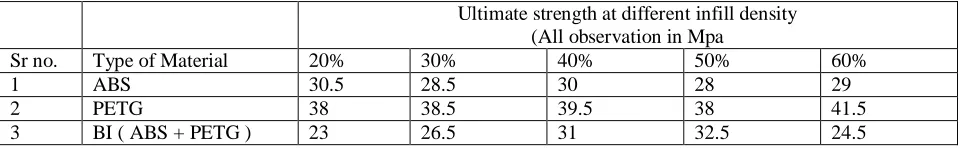
Table 4: Observation of specimen.
Ultimate strength at different infill density (All observation in Mpa
Sr no. Type of Material 20% 30% 40% 50% 60%
1 ABS 30.5 28.5 30 28 29
2 PETG 38 38.5 39.5 38 41.5
3 BI ( ABS + PETG ) 23 26.5 31 32.5 24.5
21 Fig. 4: specimen after testing.
Design of Experiment: Taguchi method:
Table 5: variable parameter at three level. Sr.
no Process parameter
Levels
Level 1 Level 2 Level 3
1 Type of
material/Density
1.07 1.25 1.16
2 Infill density 20% 40% 60%
3 Temperature 2200 c 2300 c 2400 c
On the basic of three variable factor at three level were selected for the orthogonal array, taguchi L9 array were selected for validation the observation. The most influence factor for maximum strength among three variable factor were experimentally sticking out through result of the analysis graph of signal- noise relation shown in table 5.3 that would provide minitab statistics software .
Taguchi‟s Design :
22 We take the three variable factor like infill density, material, temperature at 3 level for L9 orthogonal array, is employed for experiment. the variable factor with their level shown in Table 5.2
Table 6: L9 Programme Array
A (Material/Density) B ( Infill Density) C (Temperature)
1 1 1
1 2 2
1 3 3
2 1 2
2 2 3
2 3 1
3 1 3
3 2 2
3 3 1
Taguchi Analysis: Strength versus Material, Infill density, Temperature/.
Table 7: Signal to Noise ratios response for „Larger is better‟
Level Material Density
( G/cm3)
Infill Density ( % ) Temperature ( Celsius)
1 29.49 29.51 30.37
2 28.28 33.43 29.64
3 31.71 29.54 29.47
Delta 3.43 0.93 0.90
Rank 1 2 3
Taguchi orthogonal array L9 means number of programme runs is 9. According to delta value in table 5.3 material is more influence factor for strength. More of delta value indicate the most influence for strength. Other factor infill density and Temperature are also affect the strength greater to less.
1 . 2 5 1 . 1 6
1 . 0 7 3 2 3 1 3 0 2 9 2 8 6 0 4 0 2 0
2 4 0 2 3 0
2 2 0 3 2
3 1
3 0
2 9
2 8
M A T E R IA L D E N S IT Y ( G / C M 3 )
M e a n o f S N r a ti o s
IN F IL L D E N S IT Y ( % )
T E M P E R A T U R E ( C E L S IU S )
M a i n E f f e c t s P l o t f o r S N r a t i o s
D a ta M e a n s
S ig n a l- to - n o is e : L a r g e r is b e tte r
23 The three s/n ratio graph shown between 3 variable process parameter and tensile strength. Material-Strength graph shown the PETG material have more strength which is 31.71mpa. Infill density- strength graph shown the 40% density have more strength instead 60% density. Temperature-strength graph shown the at 2200c heaving maximum strength instead other temperature level.
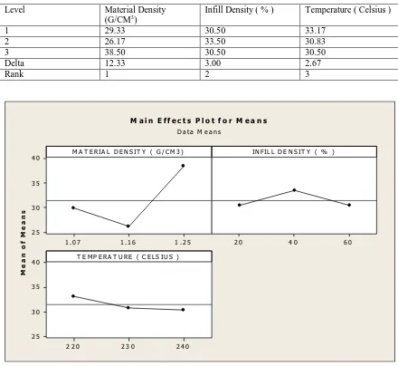
Table 8: Response Table for Means
Level Material Density
(G/CM3)
Infill Density ( % ) Temperature ( Celsius )
1 29.33 30.50 33.17
2 26.17 33.50 30.83
3 38.50 30.50 30.50
Delta 12.33 3.00 2.67
Rank 1 2 3
1 . 2 5 1 . 1 6
1 . 0 7 4 0 3 5 3 0 2 5 6 0 4 0 2 0
2 4 0 2 3 0
2 2 0 4 0
3 5
3 0
2 5
M A T E R IA L D E N S IT Y ( G / C M 3 )
M e a n o f M e a n s
IN F IL L D E N S IT Y ( % )
T E M P E R A T U R E ( C E L S IU S )
M a i n E f f e c ts P l o t f o r M e a n s
D a ta M e a n s
Fig.6: Main effect of Means Table 8: Experimental Results. Metrial
Density (Kg/m3)
Infill Density (%)
Temperature ( Celsius )
Strength ( Mpa)
SNRA1 (signal to noise ratio )
MEAN1
1.07 20 220 30.5 29.6860 30.5
1.07 40 230 30.0 29.5424 30.0
1.07 60 240 29.0 29.2480 29.0
24
1.25 40 240 39.5 31.9319 39.5
1.25 60 220 38.0 31.5957 38.0
1.16 20 240 23.0 27.2346 23.0
1.16 40 220 31.0 29.8272 31.0
1.16 60 230 24.5 27.7833 24.5
CONCLUSION
1. The environmental factor like temperature, air velocity, humidity are affect in finishing and processing of FDM printer which should be kept in under controlled for good finishing and fluent FDM process.
2. PEGT material have maximum strength at 40% infill density with 2200c nozzle temperature among other consider materials so 40% infill density is optimal density range for maximum tensile strength.
3. Tensile strength is increase with the infill density up to 40% after beyond this limit its decrease with the increase in infill density.
4. The research experiment given as a result the factor material, infill density and temperature are major influence factors from greater to lesser for enhance the tensile strength of products, that can be confirmed in table 1.8.
REFERENCES
[1]. Newman, S. T., Zhu, Z., Dhokia, V., & Shokrani, A. (2015). Process planning for additive and subtractive manufacturing technologies. CIRP Annals, 64(1), 467-470.
[2]. Karunakaran, K. P., Suryakumar, S., Pushpa, V., & Akula, S. (2010). Low cost integration of additive and subtractive processes for hybrid layered manufacturing. Robotics and Computer-Integrated Manufacturing, 26(5), 490-499.
[3]. Novakova-Marcincinova, L., & Novak-Marcincin, J. (2013). Experimental testing of materials used in fused deposition modeling rapid prototyping technology. In Advanced Materials Research (Vol. 740, pp. 597-602). Trans Tech Publications.
[4]. Ahn, S. H., Montero, M., Odell, D., Roundy, S., & Wright, P. K. (2002). Anisotropic material properties of fused deposition modeling ABS. Rapid prototyping journal, 8(4), 248-257.
[5]. Boschetto, A., & Bottini, L. (2016). Design for manufacturing of surfaces to improve accuracy in Fused Deposition Modeling. Robotics and Computer-Integrated Manufacturing, 37, 103-114.
[6]. Wu, W. Z., Geng, P., Zhao, J., Zhang, Y., Rosen, D. W., & Zhang, H. B. (2014). Manufacture and thermal deformation analysis of semicrystalline polymer polyether ether ketone by 3D printing. Materials Research Innovations, 18(sup5), S5-12.
[7]. Ramli, F. R., Jailani, M. I., Unjar, H., Alkahari, M. R., & Abdullah, M. A. (2015). Integrated recycle system concept for low cost 3D-printer sustainability. Proc. Mech. Eng. Res. Day, 1, 77-78.
[8]. Herrmann, K. H., Gärtner, C., Güllmar, D., Krämer, M., & Reichenbach, J. R. (2014). 3D printing of MRI compatible components: Why every MRI research group should have a low-budget 3D printer. Medical engineering & physics, 36(10), 1373-1380.
[9]. Peng, A., & Xiao, X. (2012). Investigation on reasons inducing error and measures improving accuracy in fused deposition modeling. Advances in Information Sciences and Service Sciences, 4(5).
[10]. Nazan, M. A., Ramli, F. R., Alkahari, M. R., Sudin, M. N., & Abdullah, M. A. (2016). Optimization of warping deformation in open source 3d printer using response surface method. Proceedings of Mechanical Engineering Research Day, 2016, 71-72.
[11]. Bernard, A., & Fischer, A. (2002). New trends in rapid product development. CIRP Annals, 51(2), 635-652. [12]. Chua, C. K., Leong, K. F., & Lim, C. S. (2010). Rapid prototyping: principles and applications (with companion
CD-ROM). World Scientific Publishing Company.
[13]. Noorani, R. (2006). Rapid prototyping: principles and applications.
[14]. Montero, M., Roundy, S., Odell, D., Ahn, S. H., & Wright, P. K. (2001). Material characterization of fused deposition modeling (FDM) ABS by designed experiments. Society of Manufacturing Engineers, 10(13552540210441166).
[15]. Kumar, S., Kumar, C. D. S., & Chhabra, D. (2015). Analysis of SEAHN demand distance vector in Wireless
mobile Ad-hoc Network. International Journal of Enhanced Research In Science, Technology & Engineering (ISSN: 2319-7463), 4(7), 273-281.
25
[17]. Chhabra, D. Optimization of an Automotive Rear Dead Axle using CAE Tool.
[18]. Deswal, S., Narang, R., & Chhabra, D. (2019). Modeling and parametric optimization of FDM 3D printing
process using hybrid techniques for enhancing dimensional preciseness. International Journal on Interactive
Design and Manufacturing (IJIDeM), 1-18.