Advanced Ceramics Progress
J o u r n a l H o m e p a g e : w w w . a c e r p . i r
Modeling and Experimental Study of Pyroplastic Deformation for Ceramic
Materials during Liquid Phase Sintering Process
H. Yaghoubi, E. Salahi*, F. Taati Asil
Department of Ceramic Engineering, Material and Energy Research Center (MERC), Karaj, Iran.
P A P E R I N F O
Paper history:
Received 26 February 2017
Accepted in revised form 03 October 2017
Keywords:
Rheological behavior Densification Hard porcelain Liquid phase sintering Numerical-experimental analysis
A B S T R A C T
In this paper, the numerical-experimental method has been developed to study the pyroplastic deformation of hard porcelain ceramic body during liquid phase sintering process. The pyroplastic deformation mainly depends on the rheological and thermal properties of the ceramic materials. In order to study these properties experimentally, the raw materials of standard hard porcelain mixture as a ceramic body were designed and prepared. For modeling, the finite element method is implemented in the CREEP user subroutine code in ABAQUS for the ceramic specimens during the liquid phase sintering process. Densification results confirmed that the bulk viscosity was well-defined with relative density. It has been shown that the shrinkage along the normal axis of slip casting is about 1.5 times larger than that of the casting direction. The stress analysis proved that the sintering stress is more than the hydrostatic stress during the entire sintering time so, the sintering process occurs completely. Dilatometry, SEM, XRD investigations as well as bulk viscosity simulation results confirmed that the “mullitisation plateau” was presented as a very little expansion at the final sintering stage, because of the highly amount of mullite formation.
1. INTRODUCTION1
One of the most important stages in ceramic manufacturing process is the sintering process. During this stage, ceramic part undergoes thermo-mechanical loadings which lead to shape deformation of the sintered body. Not only do deformation, deflection, and cracks occur but also non-uniform shrinkage takes place in the sintered bodies [1-5]. The loss of a product’s final shape can be defined as the pyroplastic or viscose flow deformation which takes place more frequently in highly vitrified ceramic bodies such as porcelains [2-4]. This loss in dimensional precision and deformation during sintering process leads to increase the ceramic body production cost, especially if the sintered ceramic body needs machining or finishing process [3-5]. Therefore, prediction and modification of the distortion in a ceramic body during sintering process has attracted many researchers and producers to develop models to describe the sintering process, but the road to the commercial benefits is still too far [4-7]. As a routine, the non-economical trial and error method is usually carried out to predict and modify the final dimension and obtain the desired ceramic parts after sintering. The
1*Corresponding Author’s Email:[email protected] (E. Salahi)
Finite Element Method (FEM) is an alternative cost-benefitted procedure to predict the shape instabilities during the sintering process [3-7]. Therefore, understanding the rheological and thermal behavior of green ceramic compacts during liquid phase sintering process is essential. The rheological behavior is defined as the resistance against viscose flow deformation and shrinkage [1-4]. Although it is a function of the physical and thermo-mechanical properties of the material e.g. relative density, temperature, grain size, diffusion coefficient, and activation energy, it can be parameterized only by the shear, bulk, and dynamic viscositities. There are considerable conceptual and experimental difficulties to determine the rheological parameters in ceramic materials during the liquid phase sintering process [1-8]; however, some literatures propose different methods and models for determining these parameters [5]. The shear viscosity ( ), expressed in a form very similar to the bulk viscosity ( ) and then, approximated by assuming =0.6 as suggested by Riedel et al., just before liquid formation [6-8]. Moreover, the uniaxial dynamic viscosity can be determined by the creep test [4-7]. Another approach proposed in the literature is that, at low stresses (about 1 Mpa), the green ceramic body undergoing densification can be treated as a linear viscous material [4, 10-11]. So, to overcome these problems, an alternative is the
finite element simulation by the aids of some economical experimental tests [2-9]. The other effort has been devoted to the development of the theory of sintering to predict the final density and dimensions. However, the major challenges here are, (i) how to
predict both the anisotropic shrinkage and
heterogeneous densification, (ii) how to take the simultaneous effect of gravity and friction force into account, and (iii) how to measure the sintering and hydrostatic stress through the ceramic body during liquid phase sintering process [1-7]. These challenges define the thermal behavior of ceramic body during liquid phase sintering. Determining these key parameters is essential for ceramic manufacturers to estimate the densification process and final shape of ceramic body. The major objective of this paper is to develop a numerical-experimental method to study both rheological and thermal behavior of the hard porcelain ceramic body during the liquid phase sintering process. For this purpose, shape distortion, viscous flow deformation, anisotropic shrinkage and heterogeneous density of hard porcelain body have been addressed. The other novelties of this paper are to accurately determine (i) the dynamic viscosity, (ii) relative density distribution, and (iii) deformation evolution as a function of sintering time. The continuum model is used based on the sintering kinetics of a porous nonlinear-viscous material. This macroscopic model is implemented using ABAQUS through the CREEP subroutine. The present study is organized as follows: section 2 includes the experimental procedures for preparing hard porcelain samples in different geometries. Section 3 presents the sintering model and the constitutive law including initial and boundary conditions. Section 4 describes the numerical procedure to implement the model through the CREEP subroutine in ABAQUS. Section 5 presents a comprehensive comparison between experimental and simulation results, and the last section dedicates to simulation validation by the aid of one real industrial sample.
2. MATERIALS, METHOD
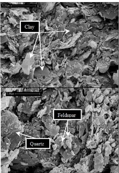
The standard hard porcelain body was formulated by quartz, feldspar, and clay. The chemical and mineral compositions had the main effects on the pyroplastic deformation [12], therefore the phases of raw materials have been determined by X-ray diffraction (XRD) (Fig. 1).
All of the non-plastic raw materials such as Feldspar and Quartz and some parts of a plastic material such as Clay were charged to the laboratory ball mill, after 20 hours milling, the suspension was mixed with the leftover Clay in the laboratory mixer to prepare the final ceramic slurry. The solid concentration was held constant at 66% weight. The density of slip was
determined by using a pycnometer and was held at 1690 gr/lit.
Figure 1. XRD patterns of raw materials
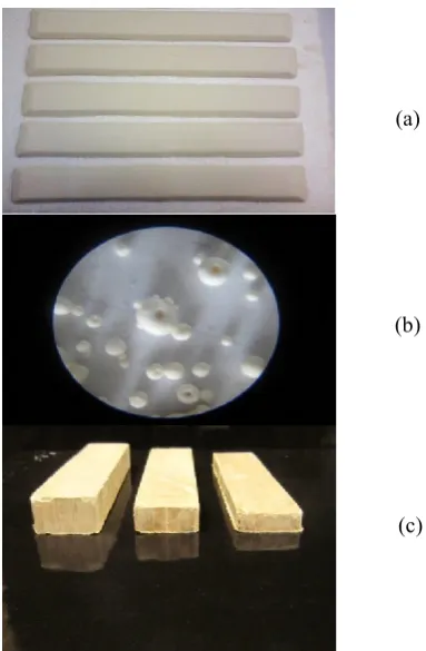
The Fordcup viscosity of the slurry was 85 sec. The distribution of particle size of the slurry was determined (d10=0.98, d50=3.89, d90=11.84) m by a laser particle size analyzer (Fritsch Particle Sizer ‘analysette 22’. The samples were shaped by two methods, first by slip casting in a plaster of Paris mold and second by the uniaxial press of granules in steel mold. The granules were produced from the ceramic slurry by the laboratory spray drier. The samples are shown in Fig. 2.a and b. The spherical granules after spray drier process are also shown in Fig. 2.c.
Figure 2. (a) Dried slip casting samples, (b) uniaxially pressed samples and (c) raw material granules after spray drier (100X)
(a)
(b)
Dimensions of rectangular dried casting samples were 5.836260 mm, and the pressed samples were 10322 mm with different thicknesses (6, 9.5, and 16.5 mm). To evaluate the simultaneous influence of gravitational and frictional forces, three different configurations as shown in Fig. 3 were designed.
The sample on a refractory support in Fig. 3.a will experience a maximum influence of friction and minimum gravitational force, the sample on refractory support in Fig. 3.b will experience a minimum influence of friction and maximum gravitational force, whilst the sample on refractory support in Fig. 3.c will experience a combination both effects.
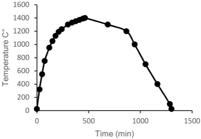
Figure 3. (a) Midpoint deflection test and (b) sinter bending test set up (c) free sintering sample The samples were sintered according to isothermal firing curve in Figure 4.
Figure 4. Designed firing curve in laboratory electrical furnace.
The heating and cooling rate was 5.6 and 1.65 C°/min,
respectively. The temperature was increased
monotonically to a sintering hold temperature and reduced to room temperature afterward.
The experimental tests including the shrinkage behavior of specimens along different direction, tensile strength, water absorption, bulk density, permanent linear change (PLC), microstructure evaluation, phase analysis, and dilatometry were used to characterize the thermal and rheological properties of hard porcelain.
The pyroplastic deformation is determined by the pyroplastic index (PI) that identifies the tendency to deformation of a specimen submitted to gravity during its firing [8]. Therefore, the curvature of a specimen during its sintering over refractory support (Fig. 4a) is measured according to Equation (1) [6-9]. Dynamic sintering viscosity (η) is calculated based on the Equation (2) [3-9].
=
(1)
= ̇ (2)
Where δ is the total deflection, ̇ is time time derivative of total deflection, ℎ is the sample thickness, is the distance between supports, is the bulk density of the body, and is the gravitational constant. Apparent porosity ( ), bulk density ( ) and relative density ( ) of the samples are measured according to the ASTM C20-00 (2015) standards as follows,
% = × 100
(3)
=
(4)
= 1 − θ
(5)
where , and are the wet weight, dry weight and the weight of sample suspended in the water, respectively. The microstructure of both dried and fired samples were evaluated by using Scanning Electron Microscopy (SEM) in combination with energy dispersive X-ray (EDX) spectroscopy.
The samples were prepared for SEM by grinding and polishing. The polished surfaces of samples were chemically etched in aqueous 5% hydrofluoric acid solution for 10 min. The crystalline phases of fired samples at different temperature were determined using an X-ray diffraction (XRD) with Cu-Kα radiation.The scans were recorded in the 10-90° 2θ range.
The dilatometric test was also performed to measure shrinkage during the sintering process from room temperature to 1400 °C. All of the curve fitting, parameter estimation, and error analysis were manipulated by Wolfram Mathematica 8.0 Software.
0 200 400 600 800 1000 1200 1400 1600
0 500 1000 1500
T
e
m
p
e
ra
tu
re
C
°
Time (min)
(a)
(b)
3. MATHEMATICAL MODEL
The macroscopic approach to the modeling of the sintering process with the aid of continuum mechanics was developed by V.V. Skorohod and further advanced by E. A. Olevsky. The model proposes a constitutive law for a porous green body with a two-phase material which includes a porous body skeleton phase and a void phase. The skeleton is assumed to be made-up of individual particles having a general linear-viscous incompressible isotropic behavior, and the distribution of the voids is isotropic. Therefore, the overall response is isotropic.
3.1. Constitutive low The constitutive model described in this paper follows the formulation of the continuum theory for sintering of porous viscous materials [13-24]. The Skorohod-Olevsky Viscous Sintering (SOVS) constitutive relationship for a linear viscous porous material is presented in Equation (6) [25-27]
= 2 ̇ + − ̇ (6)
The inverse expression of Equation (6), with strain rate now a function of stress for the viscous case can be written as Equation (7) [24].
̇ = ́ +( ) (7)
Where, ́ and are the deviatoric and hydrostatic parts of the true stress tensor , is the Kroneker delta, is the sintering stress, and are the effective shear and bulk viscosity of ceramic body, which are equal as [16-24],
= (1 − ) (8)
= ( ) (9)
The sintering stress or Laplace pressure is the driving force for densification due to interfacial energy of pores and grain boundaries. This stress caused by surface tension acting on the pore surface perpendicularly, can be calculated as,
= (1 − ) (10)
Where is the material surface tension, is the initial particle radius and is relative porosity [24-28]. The elastic part of the material response is assumed to be isotropic and characterized by Hooke’s Law as Equation (11) [24-27].
̇ = ̇ (11)
It’s noted that the elastic modulus of the ceramic body, depends on the relative density according to Equation (12) [15-17, 27-28].
= exp (− (1 − )) (12)
Where E0 is the elastic modulus of a fully dense
material and is the material constant, is the elastic stiffness matrix and ̇ is the elastic strain rate. The total strain in the sintering body including elastic and inelastic strain is given as [24],
= + (13)
Differentiating Equation (13) with respect to time and combining with Equation (11) gives the overall constitutive behavior as [24],
̇ = ( ̇ − ̇ ) (14)
The inelastic strain rate tensor ( ̇ ) that is formulated in Equation (7).
3.2. Conservation equations, boundary and initial conditions The other governing equations for modeling the sintering process based on the continuum mechanics are mass and momentum conservation which are given as follows [16],
̇
= − (15)
, + = 0 (16)
Where, ̇ is the time derivative of relative density ( ), ̇ is the first invariant of the strain rate, is the true stress and is the body force [16]. The initial relative density and particle size are measured to be about 0.694 and 3.9 m, respectively. The friction effect between the specimens with refractory supports is also measured based on the Coulomb friction law with an isotropic friction coefficient equal to 0.2. The Gravity was also considered as 9.81 ( ).
4. IMPLEMENTATION OF FINITE ELEMENT METHO
The finite element method (FEM) with C3D8I mesh, iterative method for equation solver and explicit/implicit integration method are used for simulation of the sintering process in ABAQUS with the user subroutine CREEP. Fundamentally, in order to evaluate the sensitivity and quality of the used mesh, the convergence of the results should be studied. That is, the results should not be changed significantly by reducing the mesh size. It has been carried out here by monitoring the relative density and deflection at the center of the samples. Furthermore, suitability of the C3D8I mesh can be inferred by fair accordance between experimental data and simulation. The logarithmic strain is used for geometrically nonlinear analysis. The relative density can be described as,
where and are the initial and final relative density, respectively. The volume strain is equal to the swelling strain in 3D sample [12-13]. The incremental creep is calculated as follow [12-13, 24],
∆ = ∆ + ∆
(18)
where ∆ ̅ and ∆ ̅ are the equivalent creep strain and the incremental volumetric swelling strain, respectively. The direction normal to the yield surface, given as follow [17-18, 29-30],
= = ́
(19)
where ́ is the deviatoric stress and is the Misses equivalent deviatoric stress. From Equation (7), the incremental form of the creep strain can be expressed as Equation (21).
∆ = ( )∆ ∆ + ́ ∆
(20)
Comparison of Equation (19) and Equation (21) leads to the relations in Equation (22) and Equation (23).
( )∆ ∆
= ∆ ̅
(21)
∆
= ∆ ̅ = ∆ ̅ ́
(22)
Hence the incremental creep strain components can be defined as follows [17-18, 29],
∆ ̅ = ( ) ∆ = − ∆
(23)
where = − ( ) is the equivalent pressure stress (hydrostatic pressure) [17-18]. To determine the shrinkage anisotropy, the factor is defined as Equation (26). where is the logarithmic strain or shrinkage in plane of the casting direction and in the transverse direction. The fraction of frictional work converted to heat was neglected in this work, because of the low weight of sample, low friction coefficient, thermal equilibrium in the small box electrical furnace and low contact area between sample and refractory holder; however, the frictional force between sample and substrate and gravitational force influence was included in the simulation.
∆ ̅ = ∆
(24)
= 100(1 − )
(25)
5. RESULT AND DISCUSSION
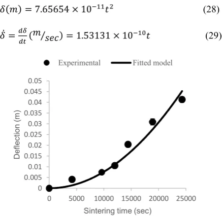
From the knowledge of the firing curve, the deflection can be plotted as a function of time during the sintering process. To find the best model, AKAIKE Information Criterion (AIC) has been used. First of all, the
Estimated Residual of Fitted Model (RSS) and AIC were calculated based on the Equation (27) and Equation (28), respectively. Then the AIC changes for different model was plotted. Finally, among the five models which have been proposed by the Wolfram Mathematica 8.0 Software, the 4th model is selected. This model has a minimum AIC, therefore, the 4th model is fitted among experimental data which gave the deflection as a function of time (Fig. 5).
= ∑ ( − ( − ) ) (26)
= ( ) + 2
(27)
where n and K are the number of samples and parameters, respectively.
Equation (29) and Equation (30) show the expressions for average deflection (4th model) and deflection rate with respect to time, where t=0 corresponds to 600 °C.
( ) = 7.65654 × 10
(28)
̇ = ( ⁄ ) = 1.53131 × 10
(29)
Figure 5. Fitted model among experimental data from midpoint deflection test.
The apparent dynamic viscosity is calculated by entering the deflection rate, bulk density, and thickness changes into Equation (2) along with the gravitational and span length constant. The viscosity was fitted as a function of temperature as follows,
( . ) = 1.6195 × 10 exp ( . )
(30)
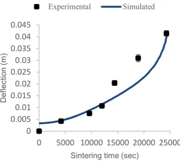
The simulation results for deflection in midpoint bending test are in a fair accordance with the experimental results that has been shown in Fig. 6. It means that the shear viscosity modulus and dynamic viscosity Equation (31) used in the simulation process are near the real ones [34-35]. The shear and bulk viscosity are directly responsible for deflection and volume shrinkage during sintering process, respectively.
0 0.005 0.01 0.015 0.02 0.025 0.03 0.035 0.04 0.045 0.05
0 5000 10000 15000 20000 25000
D
e
fl
e
c
ti
o
n
(
m
)
Sintering time (sec)
Figure 6. Deflection of the midpoint bending test obtained by finite element simulation.
The little mismatch between experimental and simulation results only for deflection about t=20000 seconds may be due to lack of the experimental precision or in the estimation of effective shear viscosity, just at this time period. The very small deflection (less than 0.003 m) at the start time (t=0) is related to elastic deformation due to thermal stress (T=600 °C). It was not possible to be measured experimentally because this elastic deflection has been recovered by decreasing temperature while the sample has been extracted from the furnace. The comparison of real shape deflection and FE simulation during the liquid phase sintering process, in sinter bending test is shown in Fig. 7.
Figure 7. Sinter bending test set-up.
From both the simulation and experiments results, it was found that the linear shrinkage along the normal axis of slip casting (X-direction) is about 1.5 times larger than that of casting direction, because of preferential orientation of clay platelets. In deflocculated porcelain slip, the clay platelets diffuse toward the surface of plaster mold and a green ceramic layer is formed by passing time. As clay particles approach the wall, they orient with the long dimension
parallel to the capillary channel direction because of water shear across the channel. As the channel narrows, the particles wedge into the wall with the orientation geometry, resulting in dense packing with preferential orientation [10-14].
Figure 8. Comparison of shrinkage in different directions (anisotropic shrinkage) during sintering process for free sintering test.
To more detail, the anisotropic shrinkage factor is plotted versus shrinkage along X-direction in Fig. 14. It shows that the is more extensive in midpoint deflection test than in free sintering mode; therefore, the shrinkage anisotropy in midpoint deflection sample is more intensive than the free sintering one. On the other hand, the gravitational force in midpoint deflection sample intensifies the anisotropic behavior of shrinkage more than the free sintering sample.
Figure 9.Anisotropic shrinkage factor for midpoint deflection and free sintering test sample.
The next simulation is carried out to investigate the evolution of relative density during the sintering time. Both experiments and simulation result show that (Fig. 10) the relative density at the middle step of sintering time (t=5000 to 20000 sec) is increased abruptly, 0 0.005 0.01 0.015 0.02 0.025 0.03 0.035 0.04 0.045
0 5000 10000 15000 20000 25000
D e fl e c ti o n ( m )
Sintering time (sec)
Experimental Simulated -0.02 -0.015 -0.01 -0.005 0
-5000 5000 15000 25000
S p at ia l d is p la ce m en t in Y -d ir ec ti o n ( m )
Sintering Time (sec)
Sample No. 1 Sample No. 2
Sample No. 3
-400 -300 -200 -100 0 100
-20 -15 -10 -5 0 5
% S h ri n k ag e an is o tr o p y ( Kx y )
% Shrinkage in the X-direction Kxy for midpoint deflection test
because of the significant increase in the amount of liquid phase. Furthermore, decreasing in the glassy phase viscosity causes to fill out the pores. It has been confirmed by SEM investigations, and the previous findings [3-4, 16, 27].
Figure 10.Evolution of relative density during liquid phase sintering process
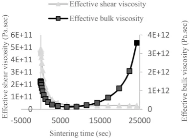
The next simulation contains the investigation about the rheological behavior of sample during liquid phase sintering process. Fig. 11 shows the effective shear and bulk viscosity changing over the sintering time. Effective shear viscosity and bulk viscosity are responsible for resistance against deformation and volume shrinkage of ceramic part during liquid phase sintering, respectively. From Fig. 11, the shear viscosity was dropped suddenly from t=0 to t= 20000. It was confirmed by the deformation of sample during this period of sintering time, which is due to vitreous phase formation and decreasing its viscosity. This indicates that the shear viscosity is not stiff enough to offer sufficient resistance against the viscous flow deformation of the sample; however, the mullite growing strengthens the body against more pyroplastic deformation and cease the falling trend of shear viscosity [10, 28].
Figure 11.Simulation of effective shear and bulk viscosity for hard porcelain samples.
From Fig. 11, the bulk viscosity was reduced from t=0 to t=10000 sec, then it was risen from t= 10000 sec to the end of sintering time. Decrease in the bulk viscosity may be related to the volume shrinkage of the sample which was started from t=0 to t= 10000 sec during the sintering process. The bulk viscosity growing can be attributed to the addition of mullite content in the ceramic body during the final stage of sintering process. It means that the sample resistance against volume shrinkage was increased by the bulk viscosity extension and secondary mullite growing, that is confirmed by the previous findings [10, 29]. In addition, a little expansion at the final stage of sintering, at the mullite formation region (about 1200 to 1400 °C) has been proved by the dilatometry result (Fig. 12).
Figure 12. Dilatometry test for hard porcelain sample from room temperature to about 1400 °C.
From thermo-mechanical point of view, the sintering stress should be more than the hydrostatic stress, during the entire of sintering time, in order for the sintering process to be occurred completely. Therefore, according to Equation 6, the green ceramic body will be sintered when the sintering stress ( ) become larger than the hydrostatic stress ( ). Sintering stress is the surface tension acting on the pore surface perpendicularly, and hydrostatic stress relates to internal pressure of entrapped air into each pore.
As shown in Fig. 13, by increasing the sintering time, more vitreous phase as well as decrease in porosity content, cause to rise the sintering stress; moreover, decrease in porosity diameter cause to increase the hydrostatic stress. It also shows that the sintering stress remained more the hydrostatic stress, during the whole of sintering time.
SEM-EDX evaluations reveal that the porcelain has a heterogeneous microstructure including broken solid materials and porosity after drying at 110 °C. Platelet shapes of clay agglomerates are obvious significantly in the green body (Fig. 14.a). Dispersed broken sharpen edges fine feldspar particles, as well as coarse quartz particles, are clear in SEM investigations for fired sample at 600 °C (Fig. 14.b).
0.66 0.69 0.72 0.75 0.78 0.81 0.84 0.870.9 0.93 0.96 0.99 1.02
-5000 5000 15000 25000
R el at iv e d en si ty
Sintering time (sec)
Experimental Simulated 0 1E+12 2E+12 3E+12 4E+12 0 1E+11 2E+11 3E+11 4E+11 5E+11 6E+11
-5000 5000 15000 25000 Eff
ec ti v e b u lk v is co si ty ( P a. se c) E ff ec ti v e sh ea r v is co si ty ( P a. se c)
Sintering time (sec)
Effective shear viscosity
Effective bulk viscosity
-1.00E-02 -8.00E-03 -6.00E-03 -4.00E-03 -2.00E-03 0.00E+00 2.00E-03 4.00E-03 6.00E-03
0 10020030040050060070080090010001100120013001400
d
L
/L
0
Figure 13. Sintering stress and hydrostatic stress changing over sintering time.
Figure 14. (a) Heterogeneous mixture of raw materials after drying at 110 °C, hexagonal plate shape clay minerals (b) Broken sharp edges fine feldspar and coarse quartz particles.
By increasing the sintering temperature up to about 1000 °C, the sharpen edges of raw materials start to be round but, the total structure remains still porous (Fig. 15.a). At about 1200 °C, the particles have been coalesced into a nearly monolithic structure containing irregular shape porosity (Fig. 15.b). By succeeding the sintering temperature up to about 1400 °C, significant vitreous phase causes to fill out the porosity, provide full dense body. The porosity morphology is also changed to be more spherical shape (Fig. 15.c).
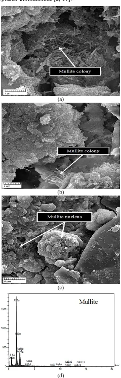
After chemical etching of the polished sample surface, SEM-EDX investigations depict the fine feldspar and
quartz particles begin to melt and provide the highly viscose liquid phase. The secondary mullite nucleus and colonies were enhanced from this liquid phase after sintering at 1200 °C (Fig. 16).
(a)
(b)
(c)
Figure 15. Microstructure of fired sample (a) at 1000 °C, porous structure including rounded edge of broken particles (b) at 1200 °C, semi-monolithic structure containing irregular shape porosity (c) at 1400 °C, full dense structure containing semi-spherical shape porosity.
In addition, SEM-EDX evaluation shows the well-grown mullite crystals with high aspect ratio, in the sample after sintering at 1400 °C (Fig. 17). These needle-shaped long crystals formed the three-dimensional interlocking networks, strengthen the 0
20000 40000 60000 80000
0 2000000 4000000 6000000 8000000
-5000 5000 15000 25000
H
y
d
ro
st
at
ic
s
tr
es
s
(P
a)
S
in
te
ri
n
g
s
tr
es
s
(P
a)
Sintering time (sec)
porcelain and increase the resistance against excessive pyroplastic deformations [2, 10].
(a)
(b)
(c)
(d)
Figure 16. (a, b, c) SEM for secondary mullite colonies and nucleus, (d) EDX of mullite colonies.
(a)
(b)
(c)
(d)
The XRD results show the phase evolution by increasing sintering temperature (Fig. 18). The kaolinite was detected as a major crystalline phase in dried sample at 110 °C. The crystalline phases including quartz and feldspar were detected in all samples, from dried at 110 °C to sintered at 1200 °C. The slight level of glassy phase and secondary mullite crystals Al2O3.2SiO2 in fired sample at 1200 °C in comparison
with the higher amount of vitreous phase and mullite crystals in sintered sample at 1400 °C were determined by the MAUD method and baseline noises [15, 30-34]. In addition, some residual quartz crystals which remain insoluble through the vitreous phase in sintered sample at 1400 °C were detected.
Figure 18. XRD patterns of sample fired at different temperature
4. CONCLUSION
The finite element simulation for the rheological properties and thermal behavior has been verified by experimental observations. The simulation results for pyroplastic deformation and densification confirmed that the shear and bulk viscosity were well-defined with relative density. The liquid phase sintering process is occurred completely because of the high level of sintering stress in comparison with hydrostatic stress, during entire of sintering process. The simulation results for bulk viscosity confirmed that the “mullitisation plateau” was occurred as a very little expansion at the final stage of sintering; moreover, it has been verified by dilatometry test. The pressure stress concentrates on the upper surface of deflected sample causing to intensify the densification process, whilst the tension stress on the mirror surface hinders the densification process. Therefore, heterogeneous density is inevitably happening in sinter bending test. Also, the FE simulation shows the anisotropic behavior of slip casting sample. The shrinkage along the normal axis of slip casting is about 1.5 times larger than that of casting direction. From all results of simulation and experimental knowledge, the design modification of
isostatic pressed ceramic part has been performed perfectly.
5-ACKNOWLEDGMENTS
The authors would like to acknowledge the financial support of Materials & Energy Research Center of Iran for this research.
REFERENCES
1. Blaine, D.C., German, R.M. and Park, S.J., "Computer modeling of distortion and densification during LPS of high-performance materials", Proceedings of the International Conference on Powder Metallurgy and Particulate Materials, Metal Powder Industries Federation, Vol. 1, (2005), 29-37. 2. Gasik, M. and Zhang, B., "A constitutive model and FE
simulation for the sintering process of powder compacts",
Computational Material Science, Vol. 18, (2000), 93-101. 3. Molla, T.T., Bjqrk, R and Olevsky, E., "Multi-scale modeling of
shape distortion during sintering of bi-layers", Computational Materials Science, Vol. 88, (2014), 28-36.
4. Bene, P. and Bardaro, D., "Numerical-experimental method to study the viscous behavior of ceramic materials", Journal of the European Ceramic Society, Vol. 34, (2014), 2617-2622. 5. Sarbandi, B., Finite element simulation of ceramic deformation
during sintering, Ph.D. thesis, Paris Institute of Technology, Mechanics of materials, (2014).
6. Blaine, D., Chung, S.H., Park, S.J., Suri, P. and German, R.M., "Finite Element Simulation of Sintering Shrinkage and Distortion in Large PIM Parts", PM Science and Technology Briefs, Vol. 6., No. 2., (2004), 13-18.
7. Blaine, D.C. and German, R.M., Sintering simulation of PIM stainless steel, International Conference on the Powder Injection Molding of Metals, Ceramics, and Carbides, San Diego, CA, (2002).
8. Mitsoulis, E., Flows of Viscoplastic Materials: Modeling and Computations, Rheology reviews, (2007).
9. Andreev, D.V. and Zakharov, A.I., "Ceramic Item Deformation during Firing: Effects of Composition and Microstructure",
Refractory and Industrial Ceramics, Vol. 50, No. 4, (2009), 45-52.
10. Tuncel, D.Y. and Ozel, E., "Evaluation of pyroplastic deformation in sanitary ware porcelain bodies", Ceramics International, Vol. 38, (2012), 1399-1407.
11. Bernardin, A.M., Medeiros, D.S. and Riella, H.G., "Pyroplasticity in porcelain tiles", Material Science and Engineering A, Vol. 427, (2006), 316-319.
12. Dellert, A., Heunisch, A. and Roosen, A., "The origin of anisotropic shrinkage in tape-cast green tapes", International Journal of Applied Ceramic Technology, Vol. 8, No. 6, (2011), 1312-1319.
13. Sighinolfi, D., "Experimental study of deformations and state of tension in traditional ceramic materials", Ceramic Materials,
Vol. 63, No. 2, (2011), 226-232.
14. Martina, S., Guessasma, M., Lechella, J. and Adenota, F. "Simulation of sintering using a non-smooth discrete element method. Application to the study of rearrangement",
Computational Materials Science, Vol. 84, (2014), 31-39. 15. Blaine, D.C., Bollina, R. and German, R.M., "Critical use of
16. Olevsky, E.A., "Theory of Sintering: from Discrete to Continuum", Materials Science and Engineering, Vol. 23, (1998), 41-100.
17. Arguello, J.G., Tikare, V., Garino, T.J. and Braginsky, M.V., Three-Dimensional simulation of sintering using a continuum modeling approach, Sandia National Laboratories, Chapter 5, (2003).
18. Olevsky, E.A. and German, R.M., "Effect of gravity on dimentional shange during sintering –part two. Shape distortion", Acta Materialia, Vol. 48, (2000), 1167-1180. 19. Shinagawa, K. and Hirashima, Y. "A Constitutive Model for
Sintering of Central Powder Compacts with Internal Structure due to Granules", Transactions of the Japan Society of Mechanical Engineers, Vol. 64, No. 617, (1998), 155-161.
20. Shinagawa, K., "Internal Stress Diagrams of Sintering Stress versus Viscosity for Graded Multilayers", JSME International Journal, Vol. 46, No. 3, (2003), 378-383.
21. Mohanram, A., Lee, S., Messing, G. and Green, D., "A novel use of constrained sintering to determine the viscous Poisson’s ratio of densifying materials", Acta Materialia, Vol. 53, (2005), 2413-2418.
22. German, R.M., Chung, S-H. and Blaine, D., "Distortion and Densification Control during Liquid Phase Sintering of High-Performance Materials", Proceedings of 8th International Conference on Numerical Methods in Industrial Forming Processes, Columbus, OH, (2004).
23. Zuo, R., Aulbach, E. and Rodel, J., "Experimental determination of sintering stresses and sintering viscosities",
Acta Materialia, Vol. 51, (2003), 4563-4574.
24. Theron, C., Determination of sintering parameters for liquid phase sintering of silicon nitride, Ph.D. thesis, State University of New Jersy, (2008).
25. Tomandl, G. and Varkoly, P., "Three-dimensional computer modeling of grain growth and pore shrinkage during sintering",
Materials Chemistry and Physics, Vol. 67, (2001), 12-16.
26. Shima, S. and Oyane, M., "Plasticity theory for porous metals", International Journal of Mechanical Sciences, Vol. 18, (1976), 285-291.
27. Lutgard, C., Jonghe, D. and Rahman, M.N., Sintering of ceramic, Handbook of Advanced Ceramics, Chapter 4, (2003). 28. Blaine, D.C., Bollina, R. and German, R.M., In situ
characterization of apparent viscosity for continuum modeling of supersolidus liquid phase sintering, Proceedings of the 4th International Conference on Science, Technology and Applications of Sintering, Institute National Polytechnique de Grenoble, Grenoble, France, (2005).
29. Lee, S., Messing, G. and Green, D., "Bending creep test to measure the viscosity of porous materials during sintering",
Journal of American Ceramic Society, Vol. 86, (2003), 877-882.
30. Porte, F., Brydson, R. and Rand, B., "Creep Viscosity of Vitreous China", Journal of American Ceramic Society, Vol. 87, (2004), 923-928.
31. Zanelli, C., Guarini, G., Raimondo, M. and Dondi, M., "The vitreous phase of porcelain stoneware: composition, evolution during sintering and physical properties", Journal of Non-Crystalline Solids, Vol. 357, (2011), 3251-3260.
32. Cheng, B. and Ngan, A.H.W., "The sintering and densification behavior of many copper nanoparticles: A molecular dynamics study", Computational Materials Science, Vol. 74, (2013), 1-11.
33. Fu, Z., Polfer, P., Kraft, T. and Roosen, A., "Correlation between anisotropic green microstructure of spherical-shaped alumina particles and their shrinkage behavior", Journal of American Ceramic Society, Vol. 98, 11, (2015), 3438-3444. 34. Yaghoubi, H., Salahi, E. and Taati, F., "Evaluation of dynamic
viscosity and rheological properties of ceramic materials during liquid phase sintering by numerical-experimental procedure",