Copyright © 2013 IJECCE, All right reserved
Adaptive Lifting Based Image Compression Scheme
Using Artificial Bee Colony Algorithm
M. Mohamed Ismail
Research Scholar, Karpagam University, CoimbatoreDr. K. Baskaran
Associate Professor, Deptt. of CSE, Government college of Technology, Coimbatore -13Abstract–The increment in the sizes of the images by the technological advances accompanies high demand for large capacities, high performance devices, high bandwidths etc. Therefore, image compression techniques are essential to reduce storage, computational or transmittal costs. Wavelet transform is one of the compression techniques especially used for images and multimedia files. This paper, proposes a framework for constructing adaptive update for lifting scheme. Artificial bee colony algorithm is used to find different update coefficient by local search, at last optimally choose the best update coefficient to get best quality of compressed image. In the update step we modifying the center pixels with the co-efficient in 8 –different direction with a considerable window size by using local search, we obtain a best directional window with a considerable size using artificial bee colony algorithm to obtain the best reconstructed image, which can be considered as an optimization task. Artificial Bee Colony algorithm which is a recent and successful optimization tool is used to determine the directional window size to produce the best compressed image in terms of both compression ratio and quality. The proposed work gives better PSNR when compared to existing methods. So, the transmission cost to transmit the encoded data and memory space to store the encoded data can be reduced with help of adaptive update lifting scheme with artificial bee colony algorithm.
Keywords–Wavelet Transform, Lifting Scheme, Adaptive Lifting Scheme, ABC Algorithm, Image Compression.
I. I
NTRODUCTIONIn the last decade, there has been a lot of technological transformation in the way we communicate. This transformation includes the ever present, ever growing internet, the explosive development in mobile communication and ever increasing importance of video communication.
Despite rapid progress in mass-storage density, processor speeds, and digital communication system performance, demand for data storage capacity and data-transmission bandwidth continues to outstrip the capabilities of available technologies. In a distributed environment large image files remain a major bottleneck within systems.
Image Compression is an important component of the solutions available for creating image file sizes of manageable and transmittable dimensions. Platform portability and performance are important in the selection of the compression/decompression technique to be employed.
The discrete wavelet transform (DWT) refers to wavelet transforms for which the wavelets are discretely sampled. A transform which localizes a function both in space and
scaling and has some desirable properties compared to the Fourier transform. The transform is based on a wavelet matrix, which can be computed more quickly than the analogous Fourier matrix.
A wavelet transform is realized using filter banks which split the image information into frequency sub bands. Due to their inherent property of producing floating point output, classical filter banks cannot in general be used in lossless compression schemes, since the coding cost for the coding of the floating-point wavelet coefficients would be prohibitively large. The lifting scheme has recently attracted much interest. It is away to implement critically sampled filter banks which have integer output.In section II A general lifting scheme is discussed and compared with adaptive lifting scheme where the update step is modified with ABC algorithm section III discusses about the proposed work and section IV explains the ABC algorithm section V explains the proposed algorithm .
II. L
IFTINGS
CHEMEThe lifting scheme has recently attracted much interest. It is away to implement critically sampled filter banks which have integer output. An algorithm for decomposing wavelet transforms into lifting steps was described in [11]. The lifting scheme can custom design the filters, needed in the transform algorithms, to the situation at hand. It is processed in space domain, independent of translating and dilating, needless of frequency analysis. In this sense it provides an answer to the algebraic stage of a wavelet construction, also leads to a fast in-place calculation of the wavelet transform, i.e. it does not require auxiliary memory. For different wavelet has different image compress effect, the compressed image quality and the compress rate is not only relational to the length of the filter, but also concerns with the orthogonality, biorthogonality, vanishing moment, regularity and local frequency. In this proposed work, we implement adaptive lifting scheme based wavelet decomposition instead of wavelet decomposition. Then with the help of artificial bee colony algorithm, we find the best directional window size to get better compression ratio with considerable quality.
Copyright © 2013 IJECCE, All right reserved but may be well-approximated by a piecewise polynomial
function. Because wavelet functions also have localized support, most of the wavelet coefficients of such a signal will be zero except those corresponding to wavelets having support near the breakpoints of the polynomial segments. It is fruitful to view the DWT as prediction-error decomposition. The scaling coefficients at a given scale (m) are "predictors" for the data at the next higher resolution or scale (m - 1).
The wavelet coefficients are simply the "prediction errors" Between the scaling coefficients and the higher resolution data that they are attempting predict. This interpretation has led to a new framework for DWT design known as the lifting scheme. Our analysis builds on this interpretation.
A. The Lifting Concept
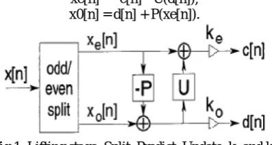
Lifting is a spatial (or time) domain construction of biorthogonal wavelets developed by Sweden. We present here an overview of our interpretation of the lifting concept. Lifting consists of iteration of the following three basic operations (Figure 1)
Split:
Divide the original data into two disjoint subsets. Although any disjoint split is possible, in the standard lifting scheme we split the original data set x[n] into xe[n] —x[2n], the even indexed points, and x0[n] = x[2n + 1],
the odd indexed points.
Predict:
Generate the wavelet coefficients d[n] as the error in predicting x0[n] from xe[n] using prediction operator P:
d[n] = x0[n]-P(xe[n] ) . (1)
Update:
Combine xe[n] and d[n] to obtain scaling coefficients
c[n] that represent a coarse approximation to the original
signal x[n]. This is accomplished by applying an update operator U to the wavelet coefficients and adding to xe[n].
c[n] = xe[n]+U(d[n]) . (2)
These three steps form a lifting stage. Iteration of the lifting stage on the output c[n] creates the complete set of DWT scaling and wavelet coefficients Cj[n] and dj[n].
At each scale, we weight the Cj[n] and dj[n] with ke and k0 respectively, as shown in Figure2. This normalizes the energy of the underlying scaling and wavelet functions. The lifting steps are easily inverted, even if P and U are nonlinear, space-varying, or non-invertible. Rearranging (1) and (2), we have
xe[n]—c[n] - U(d[n]), x0[n] = d[n] + P(xe[n]).
Fig.1. Lifting stage: Split, Predict, Update. keand k0
normalize the energy of the underlying scaling and wavelet functions.
As long as the same P and U are chosen for the forward and inverse transforms, the original signal will be perfectly reconstructed. The inverse lifting stage is shown in Fig.2.
Fig.2. Typical inverse lifting steps: undo the Update, undo the Predict, and Merge the even and odd samples.
B. Adaptive lifting scheme:
The adaptive LS is a modification of the classical lifting. Figure 3 shows an example of an adaptive ULS followed by a fixed prediction. At each sample n, an update operator is chosen according to a decision function D(x[n], y). The crucial point is that D(x[n], y) depends on y, as in the classical and space-varying lifting, but it also depends on the sample being updated. For this reason a problem arises because the decoder does not dispose of the sample x[n] used by the coder to take the decision. The decoder only knows x0[n], which is an updated version of x[n] through an unknown update filter.
In the standard lifting scheme discussed above, the update operator and the addition are fixed, in the adaptive case, the choice of these operations depends on the information locally available within both the approximation signal and the detail signal. In fact, this choice will be triggered by a so-called decision map(9).
Fig.3. Adaptive update lifting scheme
Adaptive lifting scheme performs update first, and then performs prediction according to its lifting structure. Assume x= (2m,2n), where is the input image,which is split into two signal one is average signal x and detail signal y .The detail signal y includes horizontal signal yh,
vertical signal yv, and diagonal signal yd.
The 2-D adaptive lifting structure is as follows:
Update:
Using coefficient , , , to update x :′= ( , , , ) (3)
Here, U is update operator, in which coefficients are chosen by decidable factor D .
Prediction:
Using the updated low-frequency Coefficientx’to predict , , :′ = − ( ′, , ) (4)
′ = − ( ′− ) (5)
′ = − ( ′) (6)
Copyright © 2013 IJECCE, All right reserved recording any overhead information In the standard lifting
schemes the update operator U and the addition ⊕ are fixed whereas in the adaptive lifting schemes the choice of these operations depends on the information locally available in the approximation signal x and the detail signal y. In fact, this choice will be triggered by the so called decision map : × → where is the decision set. For every possible decision € of the decision map, we have a different update operator and addition⊕ .Thus the analysis step is given by,
′( ) = ( ) ⊕ U (y)(n) (7)
Where = ( , )( )is the decision at location n. Assuming that the reversibility condition on⊕ holds for every possible decision € and it is given by
, ( ) = ′( ) ⊝ U (y)(n) (8)
Where ⊝ denotes the subtraction that inverts⊕ . The decision = ( , )( ) depends on the original signal . However, at synthesis, we do not know but “only” its update x’. In general, this prohibits the computation of
and in such cases, perfect reconstruction is out of reach. However, as there exist a number of situations in which it is still possible to recover from an posteriori decision map (10).
III. P
ROPOSEDB
LOCKD
IAGRAMFig.4. Proposed Block diagram
In existing method using wavelet transform is not giving the better quality for more detail texture image, so it gives a way for adaptive lifting scheme based decomposition. ABC algorithm Artificial Bee Colony algorithm which is a recent and successful optimization tool is used to determine the best directional window size to produce the better by local searching process. Then lossless encoding technique is used to get a perfect compressed image. After the encoding process, it is digital form so one can store or transmit the data to long distance.
Finally the image is reconstructed by applying decoding process for compressed data followed by Inverse adaptive lifting scheme.
A. Need for artificial bee colony algorithm
Choosing a global update coefficient does not give better compression ratio and quality, but artificial bee colony algorithm is used to find different update coefficient by local search at last optimally choose the best update coefficient to get best quality of compressed image.
In update, modifying the center pixels with the co-efficient in 8–different direction with a considerable window size and by using local search algorithm, to obtain a best directional window with an considerable size artificial bee colony algorithm (3).
IV. A
RTIFICIALB
EEC
OLONYA
LGORITHMArtificial Bee Colony (ABC) is one of the most recently defined algorithms by Dervis Karaboga in 2005, motivated by the intelligent behavior of honey bees. It is as simple as Particle Swarm Optimization (PSO) and Differential Evolution (DE) algorithms, and uses only common control parameters such as colony size and maximum cycle number. ABC as an optimization tool, provides a population-based search procedure in which individuals called foods positions are modified by the artificial bees with time and the bee’s aim is to discover the places of
food sources with high nectar amount and finally the one with the highest nectar(2).
In ABC system, artificial bees fly around in a multidimensional search space and some (employed and onlooker bees) choose food sources depending on the experience of themselves and their nest mates, and adjust their positions. Some (scouts) fly and choose the food sources randomly without using experience. If the nectar amount of a new source is higher than that of the previous one in their memory, they memorize the new position and forget the previous one. Thus, ABC system combines local search methods, carried out by employed and onlooker bees, with global search methods, managed by onlookers and scouts, attempting to balance exploration and exploitation process [1].
To decide whether a solution is exhausted or not, a counter is used to store the number of times that it was exploited. In other words the counter holds the number of the local searches in the neighbourhood of that solution. After a new solution is inserted in the population in a phase, the counter is reset to 0[6]
Copyright © 2013 IJECCE, All right reserved
A. Initialization Phase
In the initialization phase of the algorithm, an window size is chosen within the maximum boundaries of each pixels.
area=1+floor(maxarea*rand(1)); row=5+floor(r*rand(1));
col=5+floor(c*rand(1));
B.
Employed bees’ phase
In the employed bees’ phase, a local search in the
neighbourhood of each directional window, represented by
xi, is conducted, which is defined by using :
a1=img(row-area,col-area); b1=img(row,col-area); c1=img(row+area,col-area); d1=img(row+area,col+area);
If we get better fitness than before ,then memorize the current one.
if(localPSNR>prevPSNR) prevPSNR=localPSNR; bestimg=reconstimg;
After generating a new neighbour solution (υi) by local search, the fitness (quality) of new solution is evaluated and the better one is kept in the population. Here the counter is incremented for each local search up to 8 level(4).
C.
Onlooker bees ‘phase
In the onlooker bees’ phase, a roulette wheel selection
scheme is employed to get a best directional window for various size from 1 to M in terms of it fitness value. In roulette wheel selection, each solution is assigned a probability value (Eq. 6.1) proportional to its fitness value:
=∑ (9)
After the source is evaluated, a greedy selection is used and the onlooker bee either memorizes the new position by forgetting the old one or keeps the old one. Here the counter is incremented for each local search up to maximum window size M(5).
D. Scout
bees’ phase
A counter storing the number of non-progressive local searches exceeds the predetermined number (called
“limit”), the solution associated with this counter is
assumed to be exhausted. When a source (solution) is exhausted, it is abandoned and a new random solution is generated(7).
V. P
ROPOSEDA
LGORITHMIn existing method , decomposing the image using wavelet transform, whereas in proposed method, decomposing the image using wavelet lifting scheme and then apply the artificial bee colony algorithm in the update process to get a considerable quality.
A. Algorithm steps:
Step 1:
Acquire Input Gray scale Image. img=imread('cameraman.tif');Step2:
Split the image into odd and even pixel regions. odd=img(1:2:end,1:2:end);even=img(2:2:end,2:2:end);
Step 3:
Decompose the image for next prediction step as (odd-even).Step 4:
For prediction of co-efficient, fix the maximumcoverage size as ‘M’ and initialized ‘K=0’.Where M is
maximum window size ,upto which it will do local search for each center pixels. In our program we take maximum window size as
maxarea=5;
Step 5:
Scan each pixel in the decomposed image and calculate its present fitness value and compression ratio.Step 6:
Call direction finding algorithm to predict ‘a’ and ‘b’ co-efficient of all 8- direction combination.a1=img(row-area,col-area); b1=img(row,col-area); c1=img(row+area,col-area); d1=img(row+area,col+area);
D1 V1 D2
D1 V1
H1 H1 H1 X H2 H2
D3 D3 V2 D4
D3 V3 D4
Fig.6.Directional coefficient for center pixel ‘x’
a2=img(row-area,col+area); b2=img(row,col+area); c2=img(row+area,col+area); d2=img(row-area,col+area);
Where x is an center pixel to be update
H1 is predicted coefficient in horizontal left direction H2 is predicted coefficient in horizontal right direction V1 is predicted coefficient in vertically top direction V2 is predicted coefficient in vertically down direction D1 is predicted coefficient in diagonally top left direction D2 is predicted coefficient in diagonally top right direction D4 is predicted coefficient in diagonally bottom left direction
D5 is predicted coefficient in diagonally bottom right direction
Step 7:
Calculate update weight by using Update lifting formula for each direction prediction and find MSE and compression ratio for all combination.For example:
Find the MSE for all directional combinational prediction for center pixel and update it for the center pixel which having better MSE value by using artificial bee colony algorithm.
Two measures are commonly used to evaluate the perceptual quality:
The Mean Square Error (MSE). It represents the mean squared error between the compressed and the original image and is given by:
The lower the value of MSE, the lower the error.
Copyright © 2013 IJECCE, All right reserved
Step 8:
Memorize the best individual MSE, CR and itsdirection using ABC local search (11).
Step 9:
Iterate K from (0 to M).here we going to predict and update the best value for different range of window size.For example: For a maximum window size of 5.
We want to find best directional update for center pixel using abc algorithm for
i) Window size 5 ii) Window size 4 iii) Window size 3 vi) Window size 2 v) Window size 1
atlast by, using abc algorithm doing comparisional search with all possible window size and update best directional window size value for the center pixels
Step 10:
Using ABC local search, memorize the best window size in terms of its MSE and CR for each reference pixel.VI. E
XPERIMENTALR
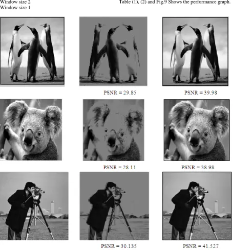
ESULTSThe proposed algorithm is tested on many standard images of size (256×256).The pepper image has high PSNR when compare to other images.
The Reconstructed images are shown in figure 7 and figure 8. The results are tabulated for various images in Table (1), (2) and Fig.9 Shows the performance graph.
Fig.7. Reconstructed Images with wavelet transform and lifting with ABC
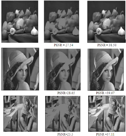
Copyright © 2013 IJECCE, All right reserved
Fig.8. Reconstructed Images with wavelet transform and lifting with ABC
(a) Original Image (b) Output of Wavelet Transform (c) Output of Lifting Scheme with ABC Table 1: Comparison Table for Cameraman Image
Compre ssion Ratio
With Wavelet Transform
With Lifting Scheme using ABC
PSNR in dB
PSNR in dB
Encoding Time
sces
Decoding Time
secs
30 33.135 40.52 4.550 1.732
40 29.635 38.11 4.451 1.727
50 27.135 36.03 4.372 1.717
60 25.635 35.86 4.265 1.702
70 23.135 32.31 4.211 1.687
Table 2.Comparison Table for Peppers Image Compr
ession Ratio
With Wavelet Transform
With Lifting Scheme using ABC
PSNR in dB
PSNR in dB
Encoding Time
secs
Decoding Time
secs
30 27.556 38.90 4.487 1.865
40 25.056 37.78 4.456 1.800
50 23.556 35.97 4.011 1.782
60 20.956 34.42 3.966 1.722
Copyright © 2013 IJECCE, All right reserved Fig.9. comparison graph of PSNR obtained from proposed
method
VII. C
ONCLUSION ANDF
UTUREE
NHANCEMENTSIn this paper ABC algorithm is applied to adaptive lifting scheme based decomposition to find the optimal directional window size to obtain satisfactory compression and quality. ABC algorithm is implemented in update process of lifting scheme to give better PSNR. From the experimental result, it is concluded that proposed method give improved quality compare to existing method. It gives the way for reduces in data to represent the image and decrease in transmission bandwidth. so, the transmission cost and memory cost is reduced with help of proposed method.
In future work, Artificial bee colony algorithm can be implement in the thresholding process to reduces the number of coefficient representing the image by optimally choosing the thresholding value to get more better compression and quality.
R
EFERENCES[1] B. Akay and D. Karaboga, Parameter tuning for the artificial bee colony algorithm, ICCCI 2009 (R. Kowalczyk N.T. Nguyen and S.-M. Chen, eds.), LNAI, vol. 5796, 2009, pp. 608–619. [2] J. Chen, M. Yang, Y. Zhang, and X. Shi, Ecg compression by
optimized quantization of wavelet coefficients, ICIC 2006, LNCIS, vol. 345, Springer-Verlag Berlin Heidelberg, 2006, p. 809814.
[3] R.R. Coifman and M.V. Wickerhauser, Entropy-based algorithms for best basis selection, IEEE Transactions on InformationTheory 38 (1992), no. 2, 713–718.
[4] V. U Kale and N. N. Khalsa, Performance evaluation of various wavelets for image compression of natural and artificial images,International Journal of Computer Science and Communication1 (2010), no. 1, 179–184.
[5] D. Karaboga, An idea based on honey bee swarm for numericaloptimization, Tech. Report TR06, Erciyes University, Engineering Faculty, Computer Engineering Department, 2005. [6] D. Karaboga and B. Akay, A survey: Algorithms simulatingbee
swarm intelligence, Artificial Intelligence Review 31 (2009),no. 1, 68–55.
[7] A modified artificial bee colony (abc) algorithm forconstrained optimization problems, Applied Soft Computing (InPress).
[8] Z. Wang, A. C. Bovik, H. R. Sheikh, and E. P. Simoncelli, Imagequality assessment: From error measurement to structural similarity,IEEE Transactios on Image Processing 13 (2004), no. 1,600[9] Z. Ye and Ye Y. Mohamadian, H., Digital image waveletcompression enhancement via particle swarm optimization, 2009IEEE Int. Conf. on Control and Automation (Chrisrchurch, NewZeland), 2009, pp. 2287–2292
[10] W. Trappe and K. J. R. Liu, “Adaptivity in the lifting scheme,” in 33th Conference on Information Sciences and Systems, Baltimore, March 1999, pp.
950-[11] R. Claypoole, G. Davis, W. Sweldens, and R. Baraniuk, “Nonlinear wavelet transforms for image coding via lifting,” submitted to IEEE Transactions on Image Processing 1999.
A
UTHOR’
SP
ROFILEProf. M. Mohamed Ismail
was born on 03.05.1965 now residing at 9/10, First Street, Anbu Nagar, Sathuvachari, Vellore-632009, Tamilnadu, India. He is Working as Associate Prof, Deptt. of Computer Science at Mazharul Uloom College, Ambur -635 802, from 4.10.1989 till date .He completed his M.Sc. physics in 1987 with first class from Bharathidasan University, Trichy , PGDCA in 1988 with first class from Bharathidasan University, Trichy, M.Sc. (info Technology) in 2000 with first class from Alagappa University, Karaikudi and M. Phil. (Computer Science) in 2001 with first class from Alagappa University, Karaikudi. At present doing part - time Ph.D. in computer Science at Karpagam University. He has attended one orientation and 4 Refresher courses for Computer lecturer at various universities in Tamilnadu and have Research papers published in international journals and also have passed module I of certified Mutual fund Advisor from National stock Exchange, Chennai.
Dr. K. Baskaran
was born on 30.4.1965 now residing at Coinbatore. He is working as Associate Prof. at Government college of Technology Coimbatore. He completed his B.E degree from Annamalai University and M.E degree from Bharathiar University, Coimbatore and Ph. D. from Anna University Chennai in the year 2006 and have published many papers in national and international journals and guiding many Ph. D. scholars at present.
40 40.541 41.542 42.5