Research Journal
Volume 9, No. 28, Dec. 2015, pages 112–119
DOI: 10.12913/22998624/60797 Research Article
Received: 2015.09.09 Accepted: 2015.11.14 Published: 2015.12.04
INFLUENCE OF MARKER ARRANGEMENT ON POSITIONING ACCURACY
OF OBJECTS IN A VIRTUAL ENVIRONMENT
Filip Górski1, Radosław Wichniarek1, Wiesław Kuczko1, Przemysław Zawadzki1, Paweł Buń1
1 Faculty of Engineering Management, Chair of Production Engineering and Management, Poznan University of
Technology, Strzelecka 11, 60-965 Poznań, Poland, e-mail: [email protected]; radoslaw.wichniarek@ put.poznan.pl; [email protected]; [email protected]; [email protected]
Abstract
The paper presents results of studies undertaken by the authors, aimed at determination of character of influence of marker arrangement on real-time measurement of position and orientation of an object, using an exemplary optical tracking system PST-55. Such a system can be used for interaction in immersive Virtual Reality applications. To ensure better immersion of a user in a virtual environment, it is necessary to di -rectly translate its actions into 3D image presented by the VR application. It is pos -sible, among other things, by the application of systems for tracking user’s movements. During the presented studies, an object with infrared-reflective markers deployed on its surface was placed in the center of a rotary table, then it was measured by the tracking system to determine the influence of the object angular position on the accuracy of de -termination of its position and orientation by the examined device. The measurements were performed for several different arrangements of markers, to formulate guidelines for their deployment on objects used for work in a virtual environment.
Keywords: marker arrangement, positioning, virtual environment.
INTRODUCTION
Along with an increase of the computing power of computer processors and the perfor-mance of the graphical processing units, there is a huge development occurring in the branches of computer graphics, visualization and simulation using Virtual Reality. Because of very high costs of highly effective computer equipment in terms of performance, the simulators have been most -ly used for military purposes in the ear-ly years. As the technology was developed, the hardware prices were gradually dropping and the simula -tions aided by VR have started to be widely used for entertainment, professional trainings (espe -cially concerning medicine [1]), in some industry branches [2], specialized education and foreign language teaching [3].
The studies performed on an early stage of de -velopment of the Virtual Reality systems prove,
that immersion of a user in an artificially prepared reality allows subconscious acquiring of certain competences [4]. This phenomenon is used, among other things, for curing phobias, including arachnophobia [5] or in trainings with application of Virtual Reality, especially in design and proto -typing of new workplaces [6]. To achieve a state of immersion, it is necessary to engage as many senses of a user in interaction with the virtual en-vironment as possible.
representation of his real movements directly af -fects effectiveness of the conducted training [7]. Systems for tracking user’s movements allow the tracking of selected points (markers) on a human body or an object used by a human to interact with the virtual environment. The tracking infor-mation is usually composed of position and ori -entation data. More realistically tracked objects are present in the virtual environment, the higher immersion level can be achieved.
The aim of the presented studies was to ex -amine the accuracy of a selected tracking system. During the studies, the authors made an attempt at determination of character of influence of marker arrangement on a tracked object on a real-time measurement of position and orientation of an object, using an exemplary optical tracking sys -tem PST-55.
THEORETICAL INFORMATION
Classification of tracking systems
There are many available tracking systems and they are very much diversified if it comes to operational parameters and purchase costs. It is possible to divide the tracking systems regarding the principle of their operation. The following systems can be distinguished:
1) Mechanical tracking systems – they usually use sensors arranged in a kinematic structure [8]. The mechanical tracking systems include accelerometers and gyroscopes. An example of a mechanical tracking system is the Iner -tiaCube2, a system based on a professional accelerometer. Another example is a proto -type of a device for tracking user’s shoulder and elbow joints in real time, built in Labora -tory of Virtual Design of Chair of Manage -ment and Production Engineering of Poznan University of Technology [9]. It reads basic movements of the arm and additionally it is equipped in buttons and a joystick allowing more advanced communication with the Vir -tual Reality software applications. In such de -vices, angular measurement is of main focus – it can be realized using various converters, such as potentiometers, optical, magnetic or capacitive encoders or resolvers. The advan-tage of these systems is their independence on any base – they usually do not have a lim -ited work area.
2) Acoustic tracking systems – the acoustic sys -tems work on the basis of the detection of sonic waves. All the acoustic systems avail -able on the market emit ultrasonic impulses, which allow to determine the tracked object position thanks to known velocity of sonic wave propagation in a given medium. Calcu -lations of time needed for the ultrasounds to travel to the sensors are performed in real time and the position is determined. In most cases, the sensors are installed in a certain points of the measurement space, while the ultrasound wave emitter is put on a tracked object [10]. 3) Electromagnetic tracking systems – they mea
4) Optical tracking systems – they are based on visual object recognition, usually on base of an image from two or more cameras. This type of tracking system was used in the stud -ies presented in the paper. Optical systems can make use of markers (active or passive / retroactive) or be markerless – recognize the object or the user on the basis of some more complex algorithms. An example of a tracking system working without markers is the Kinect system made by the Microsoft company. In this device, both the infrared light, bouncing from the tracked object (a human body) and the visible light recorded by a standard camera is used. The digital camera detects the user’s posture, while the infrared detector helps to calculate the distance from the device. The optical systems tracking positions of an object on the basis of light emitted by a single di -ode or reflected by the marker are able to track only the position of the object, without deter -mination of its orientation (angular position) regarding the assumed coordinate system. In case of application of two or more markers (or detected points) together, it becomes possible to detect also the angular position of the whole set (arrangement), provided that the mutual positions of the markers do not change during the whole tracking period. It allows tracking both the position in XYZ axes and the rotation around these axes. The more markers put to -gether in a fixed arrangement, the more stable and accurate is the real-time measurement. The markers, especially the passive ones, usu -ally have small weight and size, thanks to this they do not cause discomfort during use.
For the studies, an optical tracking system was selected with possibility of tracking both the single markers and the whole arrangements, put together in any defined set of positions. This al -lowed to determine if the placement of the mark-ers on an object and shape of the object has an in -fluence on its recognition by the tracking system and the accuracy of measurement of its linear and angular position.
Characteristics of the selected tracking system
During the studies, an optical tracking system PST-55 was used, from the PS-Tech company. The device is equipped with two infrared cam -eras and diodes emitting the infrared light. The diodes enlighten the scene, allowing tracking ob -jects which reflect the infrared rays, even if other light sources are not present in the tracking area. The system is connected with a computer with a proper software installed via a RJ-45 network cable. The device allows tracking objects in a space of a pyramid shape (Fig. 1), which can be increased using several devices at once [11]. The dimensions of the tracking area can be changed by using a different lens size – in the device used in the studies, a lens of 4.5 mm was used.
The PS-Tracking software supplied by the de -vice manufacturer is used for exchange of data between the device and a computer. The software allows, among other things, a preview of the cam -era image, which ensures the possibility of evalu -ation of visibility of markers (and whole objects) placed inside the camera detection area. If the markers are too close to each other, they are not
properly detected by the system, even if they do not physically contact each other. If possible, the markers should be placed on planar surfaces.
To make it possible to track the position of a selected physical object, it is necessary to arrange a set of markers on it. The markers are supplied by the producer in a form of round elements cut out of the infrared-retroactive tape. Their bottom side is covered with a self-adhesive. At least four markers must be placed on a selected object to al -low the recognition of its position and orientation by the device. The arrangement must be recorded in the system and given a specific ID. The record -ing is realized by plac-ing the object with markers in the work space of the tracking systems’ camer -as and then fluent rotation of the object to record all the markers. The process of implementation of an object to the system is simple and it can be performed quickly, if the markers are properly lo -cated. If the markers are placed incorrectly or the object is rotated too quickly, the tracking system will be not able to determine a relation between the newly recorded points and the points recorded in a previous step.
After implementing a marker arrangement to the system (Fig. 2), an ID (a unique name) needs to be assigned to the tracked object, as well as its ordinal number. After the recording (calibration) procedure, it is possible to correct the stored ar -rangement by the removal of improperly recog -nized markers.
It is necessary to make at least four mark -ers visible to the device (both during recording and further use), if this condition is not fulfilled, the relation between the markers cannot be de-termined and the process of object recognition is immediately stopped.
STUDY DESCRIPTION
Tracked object characteristics
The presented studies are a part of the broader study, aimed at selection of the best software and hardware solutions for the medical Virtual Reality training application – simulation of the ultrasonic examination procedure. For the described studies, a modified version of the ultrasound examination device head was used. The real head was digitized using the technology of 3D optical scanning. The optical scanner Atos I from the GOM company was used for this process, of measurement area size of 125×125×125 mm.
The 3D scanning process applied to obtain a digital model of the real ultrasonic examination head is based on a structural light projected on a measured object. The light in form of stripes is de -formed on a measured object, the deformation im -age is recorded by two (or more) cameras. The data are analyzed by the 3D scanner software and in a short time, a point cloud is generated out of each scan. Such a method of obtaining data is sufficient from the viewpoint of required dimensional and shape accuracy [13], but would be not available for use in the real time tracking due to complexity of calculation algorithms. A result of the measurement was a digital model in a form of a triangular mesh (generated automatically on the basis of the point cloud). On the basis of the mesh model, a solid model was prepared in a CAD system. Additional geometry was added to the original shape of the head, to allow the placement of additional markers for better recognition by the PST-55 system.
The digital model of the ultrasonic examina -tion head was manufactured using the additive
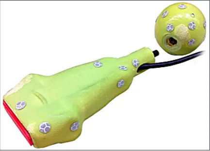
manufacturing technology of Three-Dimensional Printing (3DP). The model was manufactured in a layered manner, out of ceramic powder grains joined together by a liquid binding agent. The binding agent is deposed on the powder to form a specific section of the 3D model and the process is repeated until the model is finished. The obtained shape was then subjected to post-processing, in a 3-form of cleaning, manual grinding and infil -tration using a polyurethane resin. The two parts of the head (the base and the additional marker surface) were manufactured separately and they were assembled together using a threaded con-nection. This modular structure allowed testing of different marker surfaces. The whole device was supplemented by installation of a button activat -ed by the contact of the head with the surface of body examined during the simulated medical pro -cedure. The device is presented in the Figure 3. Methodology of the studies
The object was covered with the maximal possible number of markers, deposed in an ex -perimental way (randomly), then the arrangement was implemented in the software and given a spe-cific ID. The head was then placed on a rotary ta -ble, allowing rotation to an exact angular position, with accuracy of ±1°. The measurement system PST-55 was placed on a tripod in a distance of 1 m from the center of the rotary table. After setting a table in a specific angular position, the PST-55 system recorded the position and orientation of the measured object – the head. Total 5 measuring series for 12 positions were performed (each time the table was rotated by 30° clockwise). In each position, the data was recorded for two seconds
(the software allows a timestamp at each mea-surement, so the accuracy of time measurement was assured by the device itself), with frequency of the measurement set to 50 Hz.
For the reference, the measurements were also performed on a model object, supplied by the device manufacturer with the device. This ob-ject is a regular dodecahedron, with three markers present on each surface (Fig. 4). According to the producer, the markers on each surface are placed in unique sets of arrangements, not to confuse the system when recognizing particular surfaces and to increase precision of position and rotation tracking. The studies were performed in the same conditions.
To determine the influence of the distance to the measurement system on the measurement (tracking) results, the PST-55 system was placed in a distance of 2.2 m from the rotary table and the measurement procedure was performed again for both objects.
RESULTS
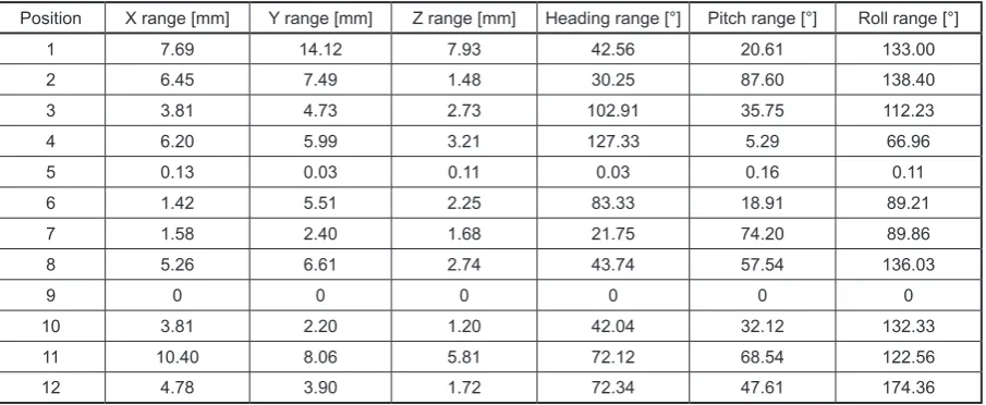
The results of measurements for each posi-tion were averaged. Then, on the basis of the gathered data, repeatability of measurements for each position was determined, with distance 1 m from the measurement system. The results – ranges (differences between maximum and minimum measurement deviation for a given angular position) are presented in Tables 1 and 2. Absolute measurements are not presented, as they are not important for the main purpose of the studies, which was to determine how differ -ent objects, with differ-ent marker arrangem-ents are recognized by the system in varying posi -tions and distances. The coordinate system con -sists of standard XYZ axes and Euler rotations defined in a standard way (heading, pitch, roll).
Fig. 3. Physical model of a modified ultrasound exam -ination head, with the additional object – a surface for additional markers. Retroactive markers of the PST-55 system arranged on the basic and additional geometry
Fig. 4. A reference object – regular dodecahedron with the optical system markers, supplied
A range of zero (recorded in certain cases in the Table) means that with a given angular posi-tion, position and orientation of the object was not recognized by the system. Such a situation happened for the ultrasonic examination head after rotation of 180° to the original position, for the model object – after rotation of 270° to the original position. Observed differences in the measurement repeatability both for position and orientation of both objects are significant. The model object supplied by the device manufac -turer is recognized in a far worse manner than the object built by the authors for the purpose of the study.
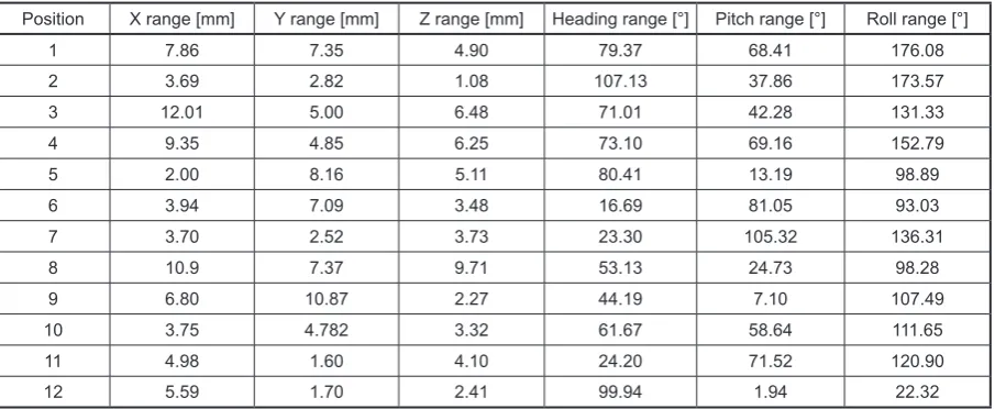
The measurements were repeated after mov-ing the trackmov-ing system to a 2,2 m distance from the measured objects. The results, in the same form as for the 1 m distance, are presented in Tables 3 and 4. The measurement results are in
-conclusive – in case of the head, the measurement repeatability improvement is clearly visible, but for two angular positions the system was not able to recognize the marker arrangement. Detection and repeatability for the dodecahedron generally improved in comparison with the 1 m measure-ment distance (the object was recognized at all positions), but it is still much below the accept -able range of values.
CONCLUSIONS
The study results are much different than general expectations. The single PST-55 device is not able to correctly recognize all positions and orientations of a single object in space. It can re -sult with an incorrect determination of position of an object in a virtual space, which could lead to Table 1. Range of results of measurement of the head object, measuring system 1 m from the object
Position X range [mm] Y range [mm] Z range [mm] Heading range [°] Pitch range [°] Roll range [°]
1 0.07 0.34 1.02 0.11 0.20 0.31
2 1.21 0.63 0.71 0.60 2.27 0.19
3 0.40 0.50 1.18 0.11 1.22 0.46
4 0.34 0.88 0.17 1.74 0.68 1.27
5 0.37 0.31 0.66 0.10 1.73 0.79
6 0 0 0 0 0 0
7 0.12 0.45 0.97 0.29 0.22 0.81
8 0.23 0.36 0.72 0.03 0.45 0.30
9 0.13 0.36 0.64 0.03 0.23 0.11
10 0.15 0.19 1.07 0.23 0.43 0.24
11 0.25 0.32 0.69 0.13 0.30 0.37
12 1.11 0.37 0.49 1.95 0.77 4.82
Table 2. Range of results of measurement of the model object (dodecahedron), measuring system 1 m from the object
Position X range [mm] Y range [mm] Z range [mm] Heading range [°] Pitch range [°] Roll range [°]
1 7.69 14.12 7.93 42.56 20.61 133.00
2 6.45 7.49 1.48 30.25 87.60 138.40
3 3.81 4.73 2.73 102.91 35.75 112.23
4 6.20 5.99 3.21 127.33 5.29 66.96
5 0.13 0.03 0.11 0.03 0.16 0.11
6 1.42 5.51 2.25 83.33 18.91 89.21
7 1.58 2.40 1.68 21.75 74.20 89.86
8 5.26 6.61 2.74 43.74 57.54 136.03
9 0 0 0 0 0 0
10 3.81 2.20 1.20 42.04 32.12 132.33
11 10.40 8.06 5.81 72.12 68.54 122.56
Table 3. Range of results of measurement of the head object, measuring system 2.2 m from the object
Position X range [mm] Y range [mm] Z range [mm] Heading range [°] Pitch range [°] Roll range [°]
1 0.05 0.04 0.07 0.05 0.04 0.07
2 0.12 0.08 0.12 0.12 0.08 0.12
3 0.23 0.26 0.20 0.23 0.26 0.20
4 0.05 0.25 0.05 0.05 0.25 0.05
5 0 0 0 0 0 0
6 0 0 0 0 0 0
7 0.02 0.07 0.11 0.02 0.07 0.11
8 0.05 0.08 0.02 0.05 0.08 0.02
9 0.31 0.11 0.26 0.31 0.11 0.26
10 0.05 0.04 0.11 0.05 0.04 0.11
11 0.04 0.02 0.09 0.04 0.02 0.09
12 0.06 0.07 0.05 0.06 0.07 0.05
Table 4. Range of results of measurement of the model object (dodecahedron), measuring system 2.2 m from the object
Position X range [mm] Y range [mm] Z range [mm] Heading range [°] Pitch range [°] Roll range [°]
1 7.86 7.35 4.90 79.37 68.41 176.08
2 3.69 2.82 1.08 107.13 37.86 173.57
3 12.01 5.00 6.48 71.01 42.28 131.33
4 9.35 4.85 6.25 73.10 69.16 152.79
5 2.00 8.16 5.11 80.41 13.19 98.89
6 3.94 7.09 3.48 16.69 81.05 93.03
7 3.70 2.52 3.73 23.30 105.32 136.31
8 10.9 7.37 9.71 53.13 24.73 98.28
9 6.80 10.87 2.27 44.19 7.10 107.49
10 3.75 4.782 3.32 61.67 58.64 111.65
11 4.98 1.60 4.10 24.20 71.52 120.90
12 5.59 1.70 2.41 99.94 1.94 22.32
negative sensations of a user and decrease in the immersion effect. This problem could probably be solved by using additional devices to track the same object and synchronize the positions of the tracked points.
For the object prepared by the authors, with a random arrangement of markers, the measure -ment accuracy and repeatability is good. Most recorded deviations do not exceed 1°, which is generally an acceptable value for the immersive Virtual Reality simulations and for this class of devices (the PST-55 system is generally con -sidered as a low-cost device). However, for the model object (originally supplied by the device manufacturer), the recognition is far below an ac -ceptable level. The angular position deviations as high as 176° allow concluding that the measure -ment system was not able to detect the marker ar -rangement properly and that the whole object was
recognized as flipped by 180° (dodecahedron is symmetrical, so this is possible). The same situa -tion happened for most of the recorded posi-tions. It is probably caused by the marker arrangements on the side surfaces of the dodecahedron not be-ing unique, which leads to the system recognizbe-ing the wrong surfaces and determining the position of the whole object in a wrong way. Increase of distance from the measurement system helped to recognize the model object in all the positions, but it did not improve the measurement repeat-ability, as opposed to the head object, where the repeatability was improved after increasing the measurement distance.
orientation of the tracked object. Further studies are planned in this topic by the authors, including both measurements and practical use of different shapes and marker arrangements.
REFERENCES
1. Hamrol, A., Górski, F., Grajewski, D., Zawadzki, P.: Virtual 3D atlas of a human body – development of an educational medical software application. Procedia Computer Science, 25, 2013, 302–314. 2. Yun-feng We, Ying Zhang, Jun-wu Shen, Tao Peng:
The virtual reality applied in construction machin -ery industry. Lecture Notes in Computer Science, Vol. 8022, 2013, 340–349.
3. Brzestrzynski W. Kształcenie odtwarzające środo-wisko immersyjne dla przyswajania języka ob -cego, Neodidagmata, 31/32, 2010/2011, 161–174. 4. Slater M., Usoh A., Steed M. Taking steps: The
influence of a walking technique on presence in virtual reality. ACM Transactions on Computer-Human Interaction (TOCHI), 2(3), 1995, 201–219. 5. Parsons T.D., Rizzo A.A., Affective outcomes of
virtual reality exposure therapy for anxiety and spe -cific phobias: A meta-analysis. Journal of Behavior Therapy and Experimental Psychiatry, 39(3), 2008, 250–261.
6. Grajewski D., Górski F., Zawadzki P., Hamrol A.,
Application of virtual reality techniques in design of ergonomic manufacturing workplaces. Procedia Computer Science, 25, 2013, 289–301.
7. McMahan R.P., Bowman D.A., Zielinski D.J., Brady R.B.: Evaluating display fidelity and interac -tion fidelity in a virtual reality game. IEEE Trans -actions on Visualization and Computer Graphics, 18(4), 2012.
8. Zhaoliang D.: 3D tracking and position of surgical instruments in virtual surgery simulation. Journal of Multimedia, 6(6), 2011.
9. Zięntek K.: Construction of a device for interac -tion in virtual environment. Poznan University of Technology (Master’s thesis), 2014.
10. Welch G., Foxlin E.: Motion tracking: No silver bullet, but a respectable arsenal. IEEE Computer Graphics and Applications, 22(6), 2002, 24–38. 11. Personal Space Tracker instruction manual, Per
-sonal Space Technologies 2011, access: www.ps-tech.com: 30.06.2011
12. Buń P., Wichniarek R., Górski F., Kuczko W.: Sys -temy śledzenia pozycji w środowisku wirtualnym w aplikacji medycznej. Innowacje w Zarządzaniu i Inżynierii Produkcji, Tom 2, 2014, 759–768. 13. Gessner A., Staniek R.: Evaluation of accuracy and
![Fig. 2. View from the camera of the PST-55 system and recognized markers, seen in the system as points in space [12]](https://thumb-us.123doks.com/thumbv2/123dok_us/8809237.1776291/4.595.126.470.577.744/fig-view-camera-pst-recognized-markers-points-space.webp)