INTRODUCTION
There are many ways to increase the aerody-namic force; the most important of them are wing mechanics and non-mechanical aerodynamic ele-ments affecting the lift force. The introduction of systems increasing the lift force allows to increase the safety and stability of the flight, especially dur-ing take-off or approach or landdur-ing when the wdur-ing operates at large angles of attack. Ensuring the safety and stability of flight in such special flight conditions is possible owing to the elements that increase the lift at low flight speeds, such mechani-cal elements are; slats, flaps, front flaps, flaperon. Non-mechanical systems include the selection of the right wing profile, wing fence, dogtooth, notch leading edge, LERX, wings cuffs, vortilons, vortex generator, continuous trailing edge flap, morphing wing and DBD plasma actuators to flow control. The manuscript presented the operation principle of selected systems increasing the lift force and fo-cused on new development trends such as continu-ous trailing edge flap, morphing wing and DBD plasma actuators for the flow controlling.
SELECTED SOLUTIONS USED
TO INCREASING LIFT FORCE
Mechanization elements affecting lift force The mechanical construction solutions that increase the stability and flight safety, especially during takeoff and landing / landing approaches when this wing works in around border attack accounts, are used in civilian and military air-crafts. Mechanization of the wing involves the use of devices called hyper-loadable or super-loadable devices, in order to increase the lift or aerodynamic resistance (spoilers and aero-dynamic brakes). Wing mechanization systems change the flow of air on the upper part of the wing’s profile by changing the shape of its pro-file, by increasing the surface or by affecting the boundary layer.
Slats
Slats are one of the most widespread wing mechanization systems that prevent the air
Review of Selected Methods for Increasing the Aerodynamic Force
of the Wing
Ernest Gnapowski
11 Department of Transport, University College of Enterprise and Administration, ul. Bursaki 12,
20-150 Lublin, Poland, e-mail: [email protected]
ABSTRACT
The manuscript presents the methods of increasing the aerodynamic force of the airfoil, currently used in aviation, and the directions of further research development. Currently, several methods are known and used to increase the aerodynamic force of the airfoil. The most widespread ones include wing mechanization systems, among others, flaps and slats. The non-mechanical elements of the wing construction that enable to increase the carrying force are used as well, among others; wing cuffs, vortilons, vortex generator. Research is being carried out on the introduc
-tion of mechanical elements that increase the lift force (Continuous Trailing Edge Flap, Morphing Wing), as well as non-mechanical elements such as plasma actuators. The manuscript describes the selected non-mechanical and mechanical elements currently used to increase the lift and the directions for the development of further research on increasing the aerodynamic force.
Keywords: high lift device, lift force, plasma actuator, DBD discharge.
Volume 13, Issue 1, March 2019, pages 60–67
https://doi.org/10.12913/22998624/103858
Research Journal
Accepted: 2019.02.12stream from separating from the airfoil. The slats action begins when the wing reaches a critical approach angle. Slats enable to im-prove the aerodynamic properties of the wing on the fly at low speeds and at large angles of attack by delaying the detachment of the air stream. Slats are the elements of wing mecha-nization placed along the leading edge of the wing. The principle of operation of slats and the impact on lift at different angles of attack is shown in Figure 1.
There are two slats constructions; movable slat shown in Figure 2b and fixed slat Figure 2a. Extending movable slats result in a gap between the slat and the wing panel, which allows the support force to be maintained at a larger angle of attack. Thus, it is possible to delay detach-ment of the boundary layer on the upper surface of the airfoil. The operation of slats consists in delaying the separation of the boundary layer by increasing its kinetic energy on the upper sur-face of the leaf by supplying it with air elements from the lower surface.
Leading edge droop
Other elements of wing mechanization changing the geometry of the front part of the wing that increase the lift force are the front flaps as shown in Figure 3. After bending the flap down, the zero value of the lift force coefficient and its maximum value are achieved at higher angles of attack, due to the increase of the mean camber line of the profile (by bending the front flap down) the maximum lift factor increases.
Kruger flap
Kruger’s flap is the variation of the front flaps which is most commonly found in passenger planes. The main part of the Kruger’s flap is a small part, the bottom plating which is located behind the leading edge, installed parallel to the leading edge as shown in Figure 4. During use, the flap rotates forward, which increases the airfoil area near the leading edge. The use of the flap changes the char-acteristics of the lift force coefficient and moves
Fig. 1. The principle of operation slats and the change of the lift force coefficient Cz from the attack angle [1]
towards the larger angles of attack. The maximum value of the lift factor increases.
Wing flaps
The design of the first wing flaps was simple. The flap structures, operational efficiency, con-figuration and complications changed over the years. The wing flaps are located in the rear part of the airfoil (trailing edge), their use allows to in-crease the lift, during take-off and landing. There are many types of flaps that differ in terms of de-sign and degree of complexity and operational ef-ficiency. The main purpose of using the flaps is to increase the lift force. The most effective flap is the three-slot flap, which is currently used most often in passenger airplanes; the design and op-eration principle is shown in Figure 5.
Three-slot flap have a very complicated ejec-tion mechanism, which is subjected to high aero-dynamic loads during take-off and landing. The flaps allow to significantly increase the surface of the wings and the mean camber line.
SELECTED ELEMENTS THAT INCREASE
THE WING LIFT FORCE
The development of aircraft brought many design solutions which enabled to improve the aerodynamic properties of the wing. The first im-portant changes in the wing design that allowed to increase the aerodynamic force were the change of the aerodynamic profile. The first aircraft wings were modelled on the wings of birds, along with the development of aeronautical structures, Fig. 3. Leading edge droop [10]
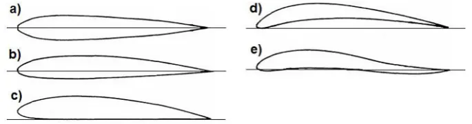
aerodynamic profiles changed, which enabled increase the stability of flight and the lift force. Nowadays, aerodynamic profiles are chosen for the construction of the aircraft due to the load, flight speed or type of aircraft. The airline profiles are selected for the construction of the aircraft due to the load, flight speed or type of aircraft. The division of the wing profiles can be made on the basis of the symmetry of profiles; flat bottom, under-cambered, symmetrical, semi-symmetrical, illustrative profiles are shown in Figure 6. The use of a particular profile depends on the purpose and use of the aircraft. The choice of profile is made in the design phase and depends on many factors and above all, on the purpose of the aircraft.
Even the correctly selected wing profile un-der certain conditions (at high angles of attack) loses the lift force. In order to counteract the loss of lift, construction offices introduce the elements that improve the flow laminarity
Wing cuffs
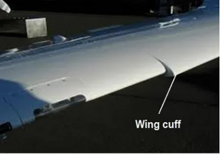
Wing cuffs are the aerodynamic modifica-tion of the front of the wing (leading edge). The
change in the shape of the leading edge applies to the profile nose at 50% to 70% of the outer wing length. This solution makes the part of the wing with the wing cuffs have a smaller angle of attack and maintain the lifting force even when a part of the wing without a cuff loses it (excessive angle of attack). The wing section with the wing cuff has a reduced angle of attack, as shown in Figure 7.
Another advantage of using wing cuffs in-volves reducing the stall speed and improving the effectiveness of the ailerons/flaps at large angles of attack [1].
Vortilons
Vortilons are permanently installed the ele-ments of wing design that constitute non-me-chanical systems improving the aerodynamic properties located on the underside of the wing. The aerodynamic elements of vortilons consist of vertical plates placed parallel to the direction of flight (perpendicular to the surface of the wing) as shown in Figure 8.
Vortilons put lesser resistance than the Vortex generator. The main function of the Vortilons is Fig. 5. Design and operation principle of three-slotted flap and ejection of flaps during various phases of flight
to generate a vortex over the upper surface of the wing only at a large angle of attack. The produc-tion of vortices at a large angle of attack has a positive effect on stalling, and also increases the effectiveness of ailerons.
Vortex generator
Another non-mechanical system is Vortex gen-erators. They are similar to the Vortilons system.
In contrast to Vortilons, the vortex generator sys-tems are located on the upper surface of the wing near the leading edge, mounted at a slight angle to the direction of flight as shown in Figure 9. Vortex generator, generate vortices in the boundary layer which prevents or delays detachment, especially at large angles of attack. Vortex generators im-prove the flow of air on wings, ailerons or control surfaces, increasing their effectiveness.
SYSTEMS USED TO INCREASE
AERODYNAMIC FORCE
Continuous Trailing Edge Flap
The Continuous Trailing Edge Flap system is a new method of changing the parameters of the airfoil. In the Continuous Trailing Edge Flap technology, changing the wing parameters, e.g. changing the position of flaps or ailerons, does not break the continuity of the surface of the wings and the trailing edge. The change of the position of the flaps or ailerons is related to the change of the shape of the wing along the trailing edge, without breaking the continuity of the sur-face and trailing edge. The design and operation of Continuous Trailing Edge Flap technology is shown in Figure 10.
The Continuous Trailing Edge Flap system, especially the end part of the wing along with the trailing edge, is divided into sections that can change position relative to each other depending on the intended deflection. Deviation of individ-ual sections does not affect the surface continuity of the wings and the trailing edge, which prevents turbulence.
Morphing Wing
Morphing Wing is a new method of changing the geometry of the wing which is inspired by the wings of birds that can change the shape and positioning of the wings depending on the con-ditions. The use of a Morphing Wing in aviation technology will allow to change the parameters of the wing depending on the flight parameters and the mission. Several geometric parameters which can be modified owing to the morphing technology are shown in Figure 11 and Figure 12. Each of the presented concepts of morphing has a particular impact on the aerodynamic ef-ficiency of the aircraft [10,11].
Fig. 7. Wing with marked wing cuffs
Rys. 8. Vortilons on the lower part of Embraer ERJ 145 wing
Fig. 9. View of the vortex generator placed on the
Morphing technology is still being studied in laboratories because it offers a range of possibili-ties to optimize the aerodynamic performance of the aircraft, focusing mainly on improving the aerodynamic efficiency and manoeuvrability.
The use of DBD barrier discharges to control the flow of the boundary layer
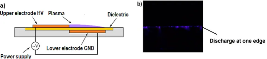
DBD plasma actuator is new solution which improves aerodynamics and flight efficiency [4]. DBD systems are placed directly on the wing surface; the lack of moving parts such as
ten-Fig. 10. Design and operation of the Continuous Trailing Edge Flap system [11,12]
Fig. 11. Illustration of morphing wing [8]
Fig. 12. Classification of morphing wing [8]
dons, cylinders or gears, valves, diaphragms constitutes a huge advantage of these systems; therefore, it does not further complicate the air-foil design. The plasma actuator is a simple de-vice, it consists of two flat electrodes separated by a dielectric, the most common configuration of the DBD system is the asymmetrical circuit shown in Figure 13a.
Plasma actuators are the devices that have many advantages over other devices influencing the flow among others:
• Plasma actuators are fully electronic and have no moving parts,
• They are thin and offer minimal resistance, • They can be laminated to the surface of the
profile,
• Their operation does not require any gaps or cavities,
• Plasma actuators can operate in constant or in-termittent modes,
• They withstand high loads,
• Plasma actuators have a quick response to feedback control.
CONCLUSION
The manuscript describes the selected ele-ments of wing design that improve the aerody-namic force. The elements of wing mechanization improving the lift force currently used in aviation, were described. These elements are mechanical systems that change the shape and aerodynamics of the wing by, for example, sliding out the slats or flaps, allows to significantly improve the sta-bility and flight safety during take-off and land-ing by increasland-ing the wland-ing area and changland-ing the wing’s chord. The next subchapter presents the non-mechanical construction elements of the wing that improve the flow around the boundary layer, focusing on ensuring the stabilization or adherence of the boundary layer flow. This task is accomplished by limiting / gluing the boundary layer or by introducing controlled disturbances in the form of vortices that enable increase the en-ergy of the boundary layer.
The next chapter describes a new solution such as Continuous Trailing Edge Flap, which is a new method of changing the parameters of the
aircraft’s wing. In the Continuous Trailing Edge Flap technology, changing the wing parameters, e.g. the position of flaps or ailerons, does not break the continuity of the surface of the wings and the trailing edge. This is a new solution cur-rently being tested in aerodynamic laboratories and tunnels. The next described system is the Morphing Wing which is a new way to change the geometry of the wing of the plane inspired by the wings of birds that can change the shape and positioning of the wings depending on the condi-tions. The last non-mechanical system described in the manuscript, affecting the change of the boundary layer flow, involves plasma actuators the operation of which is based on the produc-tion of the „ionic wind”. The high-voltage power supplies that power the plasma actuator signifi-cantly affect the operation of the DBD system, especially voltage and frequency as well as the performance. The effectiveness of plasma actua-tors also depends on the angle of attack, air flow velocity around the wing. This solution is a new method of influencing the flow in the boundary layer therefore requires a lot of research and opti-mization before implementation.
REFERENCES
1. Huenecke K., Modern combat aircraft design, Air
-lite Publishing, Shrewsbury, 1987.
2. Gnapowski E., Gnapowski S., Pytka J., Effect of Mesh Geometry on Power, Efficiency and Homo -geneity of Barrier Discharges in the Presence of
Glass Dielectric, IEEE Transactions on Plasma Science, Vol. 46, 2018, 3493-3498.
3. Gnapowski S., Gnapowski E., Duda A., Inproving of the quality food for animals by pulsed power plasma discharge, Adv. Sci. Technol. Res. J., 9(27), 2015, 58-65.
4. Seraudie A., Aubert E., Naudé N., and Cambronne J., Effect of Plasma Actuators on a Flat Plate Lami -Fig. 13. Asymmetrical plasma actuator; a) design and operation principle, b) plasma actuator during operation
nar Boundary Layer in Subsonic Conditions, 2006, 3rd AIAA Flow Control Conference, Fluid Dy
-namics and Co-located Conferences.
5. Gnapowski E., Gnapowski S., Changes in the Power Discharge in a Plasma Reactor Using Po
-rous Versus Solid Dielectric Barriers and Meshes Electrodes. IEEE Transactions on Plasma, 44(10), 2016, 2079-2083.
6. Seraudie A., Vermeersch O., and Arnal D., DBD Plasma actuator effect on a 2D model laminar boundary layer. Transition delay under ionic wind effect, 2011, 29th AIAA Applied Aerodynamics Conference, Fluid Dynamics and Co-located Con
-ferences.
7. Gnapowski E., Gnapowski S., Pytka J., The im
-pact of dielectrics on the electricalcapacity, con
-centration, efficiency ozonegeneration for the plasma reactor with meshelectrodes, Plasma Sci
-ence and Technology, 20(8), 2018, 1-7, https://doi. org/10.1088/2058-6272/aac1b6
8. Ismail N.I., Zulkifli A.H., Abdullah M.Z., Basri M.H.M., Arif M., and Hamid A., Evolution of monoplane fixed wing micro air vehicle’s shape and design. Review. In: 2nd. International Confer
-ence on Arts, Social Sci-ences & Technology 2012. 9. Gnapowski E., Effect of Mesh Electrodes Geom
-etry on the Ozone Concentration in the Presence of Micanite Dielectric. Advances in Science and Technology Research Journal, 12(4), 2018, 76–80, https://doi.org/10.12913/22998624/100340 10. Gudmundsson S., General Aviation Aircraft De
-sign. Butterworth-Heinemann 2014.
11. Sofla A.Y.N., Meguid S.A., Tan K.T., and Yeo W.K., Shape morphing of aircraft wing: Status and challenges. Mater. Des., 31(3), 2010, 1284–1292. 12. Nhan T. Nguyen and Ezra A. Tal. A Multi-Ob
![Fig. 1. The principle of operation slats and the change of the lift force coefficient Cz from the attack angle [1]](https://thumb-us.123doks.com/thumbv2/123dok_us/8805682.1774436/2.595.101.494.626.755/principle-operation-slats-change-force-coefficient-attack-angle.webp)
![Fig. 3. Leading edge droop [10]](https://thumb-us.123doks.com/thumbv2/123dok_us/8805682.1774436/3.595.83.511.57.488/fig-leading-edge-droop.webp)
![Fig. 10. Design and operation of the Continuous Trailing Edge Flap system [11,12]](https://thumb-us.123doks.com/thumbv2/123dok_us/8805682.1774436/6.595.94.506.75.197/fig-design-operation-continuous-trailing-edge-flap.webp)