INTRODUCTION
Titanium sheets are used in many areas of our life. They have a well-established position in aviation and aerospace [7, 9, 10, 30]. Titani-um sheets are increasingly used in the automo-tive [13, 14, 18, 19] and medical industries [17, 20, 21, 25], and recently also in civil engineer-ing [5] as well as in offshore structures [22, 28]. The growing interest in the use of titanium sheet products is due to the excellent properties of tita-nium, including high specific strength (strength-to-weight ratio) and good resistance to most corrosive environments. In addition, biocompat-ibility [16, 27], allowing the correct functioning of titanium implants in living organisms, is well recognized in medicine as well as osteointegra-tion with bone tissue, which creates good condi-tions for a durable and stable junction between
an implant with the bone. The wide range of ar-chitectural capabilities associated with titanium anodic oxidation are of interest to civil engineer-ing. Thanks to light interference phenomena tak-ing place at the titanium-oxide-air interfaces with continuous changing of the oxide film thickness, it is possible to obtain a gradation colour looking like rainbow [12, 29]. Anode oxidation, besides titanium coloration, has the effect of increasing the corrosion resistance of titanium products. Nu-merous titanium drawn parts are used as different kinds of casings. Civil engineering, like the aero-space industry, uses titanium’s resistance to high temperatures for the production of firewalls. The materials used in cover elements are required to ensure structural stability and to protect the users from the effects of heat and flame for a sufficient time to leave a room at the risk of fire. According to US Federal Aviation Regulations (FAR PART
NUMERICAL SIMULATION OF FORMING TITANIUM THIN-WALL PANELS
WITH STIFFENERS
Janina Adamus
1, Julita Winowiecka
1, Marcin Dyner
2, Piotr Lacki
21 Czestochowa University of Technology, Dabrowskiego 69, 42-201 Czestochowa, Poland, e-mail: [email protected], [email protected]
2 CHIRMED Manufacturer of Surgical and Medical Instruments, Mstowska 8A, 42-240 Rudniki-Czestochowa, Poland, e-mail: [email protected], [email protected]
Research Journal
Volume 12, Issue 1, March 2018, pages 54–62
DOI: 10.12913/22998624/80826 Research Article
ABSTRACT
Due to the increase in the application of titanium components made of thin titanium sheets, in the work titanium panels made of 4 mm thick sheets are analysed. To
in-crease the rigidity of the panels, some cross-shaped stiffeners were made. Such panels
enable a reduction in weight while maintaining the existing strength of the drawn parts. Three kinds of commercially pure titanium are considered: Grade 1, 2 and 3.
Numerical calculations were performed with PamStamp 2G based on the finite el -ement method. The basic mechanical and technological properties of the analysed sheets, which are necessary for numerical modelling, were determined by static
ten-sile testing. The friction coefficient was assumed based on the literature. On the basis
of the performed numerical analyses, it was stated that the proper forming of panels
with stiffeners depends not only on the drawability of the sheets but also on the tech -nological parameters such as blank holder force and frictional conditions.
Keywords: sheet, commercially pure titanium, sheet-metal forming, stiffeners, nu -merical simulation
Received: 2017.10.06 Accepted: 2018.02.01
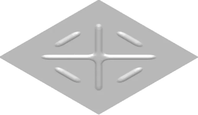
Figure 1. View of part of shielding component with cross-shaped stiffeners 23.1191), titanium sheets with a thickness of
0.016 inch (i.e. ~ 0.4 mm) are one of the materials that can be used for covers, including firewalls, without special testing for creep-resistance and heat-resistance Since shielding components do not require high strength, pure titanium sheets are used to produce these parts. The tensile strength of pure titanium sheets ranges from Rm=240 MPa for commercially pure titanium Grade 1 to about 550 MPa for titanium Grade 4. As the amount of impurities increases, the mechanical properties of titanium increase, at the expense of reducing its plasticity. Grade 1 and 2 titanium sheets have relatively good drawability, while other titanium grades, especially titanium alloys, are charac-terised by low drawability and they are prone to springback after unloading. Additionally, tita-nium has low tribological properties, which ap-pears as the formation of titanium protrusions on the steel forming tools and galling [6]. It is partic-ularly difficult to shape almost flat panels of thin titanium sheets. To stiffen large flat surfaces and reduce the tendency to warp, shallow embossing is performed on the panels. In addition, stiffen-ing ribs reduce the sheet thickness, which is es-pecially important due to the reduced mass of the shaped parts, without lowering their mechanical strength. Unfortunately, during their forming de-formations often appear which impede the assem-bly of panels and their subsequent exploitation. Problems related to shaping titanium alloy sheets including numerical modelling are discussed in [8, 11, 15, 25]. The present work is a continua-tion of the former authors’ research [1 – 4] aimed
at developing guidelines for forming titanium panels with stiffeners. The work analysis the cold forming of thin-wall panels with stiffeners in or-der to obtain optimum shaping parameters so that their flat surfaces will not deform. The analyses are performed with a commercial program PAM-Stamp 2G v. 2012 based on FEM [26], which is dedicated to supporting the design of sheet-metal forming, including tool design, formability analy-ses, try-out validation and prediction of spring-back after unloading.
NUMERICAL ANALYSES
The numerical analysis concerns forming panels with cross-shaped stiffeners as shown in Figure 1. Panels made of three grades of pure titanium: Grade 1, Grade 2 and Grade 3 are analysed. 0.4 mm thick sheets were used for their construction.
The chemical composition of the analysed commercially pure titanium grades is given in Ta-ble 1. The mechanical and technological param-eters, which are essential for numerical analyses, were determined in a static tensile test according to PN-EN ISO 6892–1:2016–09.
Numerical model
Four-node shell elements were used to model both the tools and sheet. The appropriate bound-ary conditions were assigned to each tool part, namely:
• the die was deprived of all degrees of freedom
• the punch and the blank holder can move in the direction of the Z axis thanks to applying a velocity vector to the punches and a force to the blank holder
• the blank has all degrees of freedom.
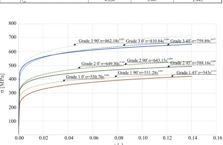
The deformed materials (sheets) were defined as anisotropic, considering Hill 48’s yield crite-rion. The strain–stress curves for the analysed sheets were described according to Hollomon’s law σ=Κ·εn, where: K – the material constant, n – the strain hardening coefficient. The mate-rial properties assumed in the matemate-rial models are given in Table 2. All the properties were deter-mined experimentally in the static tensile test.
The strain–stress curves in three characteris-tic directions: 0°, 45° and 90o to the rolling direc-tion for all the analysed sheets are presented in
Figure 3, while a graphical representation of the r-values is presented in Figure 4.
All the analysed sheets are characterised by both normal and planar anisotropy. Although high normal anisotropy shows that a sheet is resistant to material thinning, i.e. is resistant to tensile in the normal direction to the sheet surface, the planar anisotropy, which ranges from -1.612 to -0.288, is especially unfavourable in sheet-metal forming because it is a reason for uneven metal flow.
Numerical simulation results
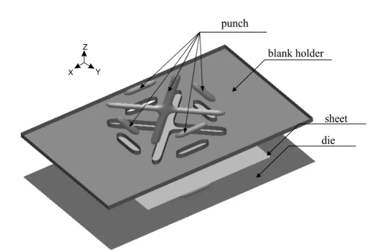
Based on the results of forming panels with two stiffeners, which are presented in [22–24], it was decided that the present numerical analyses will be performed for panels with cross-shaped stiffeners deformed in dry conditions without any lubrication. Previous studies show that the form-ing process of thin-wall panels with stiffeners should be performed in dry conditions with the smallest blank holder force, but one that provides the correct course of the process and the assumed Figure 2. Surface model of tools for forming thin-wall panels with cross-shaped stiffeners
Table 1. Chemical composition of analysed titanium sheets
Material
Element Grade 1 Grade 2 Grade 3
C 0.080÷0.008 0.007÷0.006 0.014÷0.016
Fe 0.200÷0.040 0.140 0.120÷0.130
N 0.002÷0.050 0.006÷0.008 0.007÷0.010
O 0.200÷0.070 0.100 0.210
quality of the stiffeners. The technological pa-rameters, such as the friction coefficient or blank holder force, should be selected so that the stiff-eners are formed only by stretching without draw-ing material from the flat part of the panel into the die cavity. This will prevent warping and bending of the panels and in turn it will make panel assem-bly easier and reduce the sound effects accom-panying any eventual deformation of nearly flat thin-wall panels. In the numerical calculations, according to [25], friction coefficient μ=0.4 was assumed for the technically dry conditions.
The following blank holder forces were ap-plied: 600, 800, 1000 and 1200 kN. As in the case of panels with two stiffeners, the plastic strains and sheet thinning as well as the width
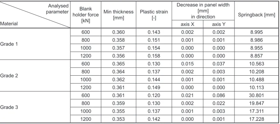
of the panels after forming (in two mutually per-pendicular directions X and Y) and springback after unloading are analysed. A summary of the numerical simulation results of forming titanium panels for all titanium grades: Grade 1, 2 and 3 is given in Table 3.
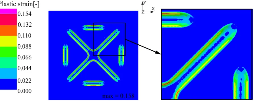
The thickness and plastic strain distributions, for example, for forming a Grade 1 titanium panel with the blank holder force of 1200 kN are pre-sented, respectively, in Figures 5 and 6.
Analysis of the numerical calculation results shows that the uniform thickness distribution in the flat part of the panel (Figure 5) was obtained for all the analysed blank holder forces. In the spots of the greatest sheet thinning occurring in the area of the stiffeners, the sheet thickness for Table 2. Material properties assumed in numerical simulations
Material
Parameter Grade 1 Grade 2 Grade 3
Young’s modulus E [GPa] 116.95 102.84 106.21
Yield point Re [MPa] 291.03 344.25 515.50
Poisson’s coefficient ν [-] 0.34 0.37 0.37
Density ρ [kg/m3] 4510 4500 4510
Material constant K [MPa] 533.57 628.45 811.87
Strain hardening coefficient n [-] 0.106 0.098 0.089
r-value
r0 2.248 2.059 0.795
r90 2.596 4.259 2.293
r45 4.034 3.447 2.445
forming with blank holder force Fb-h=1200 kN is 0.356 mm. The greatest thinning appears in the lower part of the stiffeners, while at the top of them the thinning is slight. During forming with force Fb-h=1200 kN, there are also the greatest plastic strains of 0.158 (Figure 6). Although there was no reduction in panel width in the X and Y directions (0.000 mm), the numerical simulations
indicate that unloading the panels causes signifi-cant springback, especially for the panels made of Grade 3. The change in panel width is defined as the difference between the initial width of the blank and the final width of the panel. The small-est springback of 8.857 mm was observed after forming the Grade 1 panel, which was formed with blank holder force Fb-h=1200 kN. Spring-Figure 4. r-values depending on direction of loading in-plane (0°, 45° and 90o to rolling direction) for titanium:
a) Grade 1, b) Grade 2, c) Grade 3
Table 3. Numerical results of forming titanium panels with cross-shaped stiffeners
Analysed parameter
Material
Blank
holder force
[kN]
Min thickness
[mm] Plastic strain [-]
Decrease in panel width [mm]
in direction Springback [mm]
axis X axis Y
Grade 1
600 0.360 0.143 0.002 0.002 8.995
800 0.358 0.151 0.001 0.001 8.986
1000 0.357 0.154 0.000 0.000 8.955
1200 0.356 0.158 0.000 0.000 8.857
Grade 2
600 0.365 0.130 0.015 0.037 10.563
800 0.364 0.137 0.002 0.003 10.208
1000 0.362 0.144 0.001 0.001 10.488
1200 0.361 0.149 0.000 0.000 10.113
Grade 3
600 0.361 0.120 0.021 0.086 30.801
800 0.359 0.130 0.002 0.022 19.847
1000 0.355 0.137 0.001 0.003 17.311
back is defined as the numerical distance between the corresponding nodes of the reference element and the unloaded element measured in millime-tres (see Figure 7). The springback, for example, in the Grade 1 titanium panel after unloading is presented in Figure 8.
It results from the fact that both the thickness and plastic strains in the area of the stiffeners are not even and they are not symmetrically distrib-uted. The most likely cause of such a distribution of plastic strains and sheet thickness is the large planar anisotropy and placement of the stiffeners in the panel.
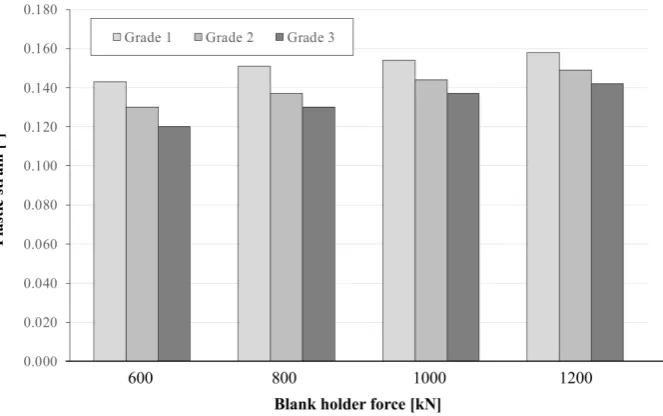
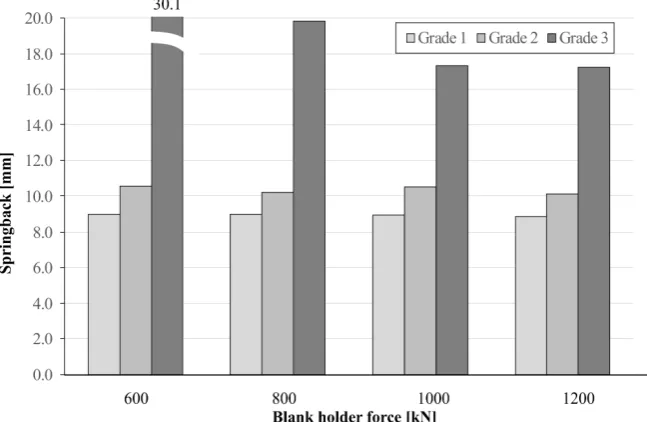
The influences of blank holder force and kind of material on the maximal plastic strains and springback value are presented in Figure 9 and 10, respectively.
Analysis of the numerical calculation results shows that the higher the blank holder force, the lower the springback is. It is because a lower vol-ume of the material from the flat part of the panels
is pulled into the die cavities, hence the stiffeners are mostly formed by stretching. Too little pres-sure allows the material to slide out of the blank holder and flow into the die cavity, as a result the panel width decreases. The panel undergoes con-siderable distortion and starts to flex. The amount of blank holder force needed to form the stiffen-ers significantly depends on the deformed mate-rial. This is clearly visible on the example of the Grade 3 titanium panel for which even a blank holder force of 1200 kN is not enough to form the panels. The springback value reaches ~17 mm. When there is no possibility to increase the fric-tion coefficient and the blank holder force, it is necessary to reconsider the shape, size and loca-tion of stiffeners in the panel, because the authors noticed that the tendency of the panels to flex and “wave” is also influenced by how the stiffeners are placed in the panels. However, to determine the optimal distribution of stiffeners in panels, further numerical analyses are required.
Figure 5. Thickness distribution in Grade 1 titanium drawn part: μ=0.4, Fb-h=1200 kN
Figure 7. Springback definition in numerical simulation
Figure 8. Springback in Grade 1 titanium drawn part: μ=0.4. Fb-h=1200 kN
Figure 9. Maximal plastic strains in titanium panels with cross-shaped stiffeners vs blank holder force and
CONCLUSIONS
The numerical calculation of forming tita-nium panels with cross-shaped stiffeners confirm the results of research on forming titanium panels with two stiffeners, described in [26–28] that:
• the possibility of the proper forming of drawn parts depends not only on sheet drawability but also on the forming parameters, such as blank holder force and frictional coefficient
• a decrease in springback is possible when the stiffeners are formed only by material stretch-ing without pullstretch-ing the material into the die cavities
• the influence of planar anisotropy should be taken into consideration during the design and distribution of stiffeners in the panels
• such panels should be performed on double-action presses or special tools which at the be-ginning of the forming process enable firm fix-ing of the blank between the die and the blank holder without the possibility of the sheet slid-ing out from under the blank holder and then forming the stiffeners.
Acknowledgements
Financial support of Structural Funds in the Operational Programme – Innovative Economy (IE OP) financed from the Euro-pean Regional Development Fund – Project “Modern material technologies in aerospace in-dustry”, No POIG.01.01.02–00–015/08–00 is gratefully acknowledged
REFERENCES
1. Adamus J. and Lacki P. Numerical analysis of forming sheet panels with stiffening ribs. Proceed -ings of the XIII International Conference on
Com-putational Plasticity. Fundamentals and Applica
-tions. COMPLAS XIII, E. Oñate, D.R.J. Owen, D. Peric and M. Chiumenti (Eds). Barcelona: CIMNE
2015, 204–215.
2. Adamus J. and Lacki P. Numerical simulation of forming titanium drawn part. Meccanica 51(2),
2016, 391–400.
3. Adamus J., Dyja K. and Więckowski W. Lubricants Based on Vegetable Oils as Effective Lubricating Agents in Sheet-Titanium Forming. Key Engineer -ing Materials 687, 2016, 163–170.
4. Adamus J., Winowiecka J. and Dyner M.
Analy-sis of forming thin titanium panels with stiffeners, Archives of Metallurgy and Materials 62(1), 2017,
175–182.
5. Adamus J.: Applications of titanium sheets in mod-ern building construction. Advanced Materials Re-search, 1020, 2014, 9–14.
6. Adamus J.: Stamping of the titanium sheets. Key
Engineering Materials, 410–411, 2009, 279–288. 7. Adib A.M.L., Baptista C.A.R.P., Barboza M.J.R.,
Haga C. and Marques C.C.F. Aircraft engine bleed system tubes: Material and failure mode analysis. Engineering Failure Analysis 14, 2007, 1605–1617. 8. Badr O.M., Barlat F., Rolfe B., Lee M-G., Hodg
-son P. and Weiss M. Constitutive modelling of high
strength titanium alloy Ti-6Al-4V for sheet form-ing applications at room temperature. International Journal of Solids and Structures 80, 2016, 334–347. 9. Boyer R.R.: Titanium for aerospace: rationale and
application. Advanced Performance Materials 2,
1995, 349–368.
10. Boyer, R. and Williams, J. Developments in re-search and application in the titanium industry in
the USA. Proceedings of the 12th World Confer -ence on Titanium, Beijing, 2011, 10–19.
11. Chartrel B. and Massoni E. Deep drawing of Ti6Al4V: Experiments and modeling over a wide
range of strain rates and temperatures. Key Engi -neering Materials, 554–557, 2013, 190–194. 12. Diamanti M.V., Del Curto B. and Pedeferri M.P.
Interference Colors of thin oxide layers on
tita-nium. Color research and application 33(3), 2008,
221–228.
13. Faller K. and Froes F.H. The use of titanium in family automobiles. Journal of Metals, 53(4),
2001, 27–28.
14. Fuji H., Takahashi K. and Yamashita Y. Applica -tion of titanium alloys for automobile parts. Nip-pon Steel Technical Raport no 88 July 2003, 70–75. 15. Hu Z., Wang C., Chen X. and Liu J. A novel form-ing method for three-dimensional thin sheet metal.
Proceedings of the Institution of Mechanical Engi
-neers, Part B: Journal of Engineering Manufacture 230(9), 2016, 1751–1755.
16. Huanga J., Zhang X., Yan W., Chena Z., Shuai X., Wang A. and Wang Y. Nanotubular topography en-hances the bioactivity of titanium implants,
Nano-medicine, 13(6), 2017, 1913–1923.
17. Jackson M.J., Kopac J., Balazic M., Bombac D., Brojan M. and Kosel F. Titanium and Titanium Al -loy Applications in Medicine. Surgical tools and medical devices, 2nd edition, eds.: Waqar Aahmed,
Mark J. Jackson. Springer International Publish -ing, Switzerland 2016, 475–518.
18. Kosaka Y., Faller K. and Fox S. P. Newly devel -oped titanium alloy sheets for the exhaust systems
of motorcycles and automobiles. JOM: the Journal of the Minerals, Metals & Materials Society 5(11),
2004, 32–34.
19. Kosaka Y., Fox S. P. and Faller K., Reichmann S.H.
Development of low cost titanium alloy sheet for
automotive exhaust applications. Proceedings of
the Minerals, Metals & Materials Society Sympo-sium, 2004, 67–76.
20. Marciniak J.: Biomaterials (in Polish: Biomateriały). Silesian University of Technology Publishing House, Gliwice, Poland, 2002.
21. Muzykiewicz W. Rękas A., Major R., Major B. and Kustosz R. Forming of prts of artificial car
-diac chambers made of titanium sheet (in Polish: Tłoczenie elementów komory sztucznego serca z blachy tytanowej. Ores and metals (in Polish: Rudy i Metale) 51(4), 2006, 212–218.
22. Nakamura S. and Homma K. Durability of Tita
-nium-Clad Steel Plates used as an Anti-Corrosion
System, Structural Engineering International
10(4), 2000, 262–265.
23. Niinomi M. Mechanical properties of biomedical titanium alloys. Materials Science and Engineering A243, 1998, 231–236.
24. Niinomi M., Liu Y., Nakai M., Liu H. and Li H. Biomedical titanium alloys with Young’s moduli close to that of cortical bone. Regennerative
Bio-materials 3(3), 2016, 173–185.
25. Odenberger E.-L., Oldenburg M., Thilderkvist P.,
Stoehr T., Lechler J. and Merklein M.: Tool devel-opment based on modelling and simulation of hot sheet metal forming of Ti–6Al–4V titanium alloy.
Journal of Materials Processing Technology 211,
2011, 1324–1335.
26. PamStamp 2G v. 2011. User’s Guide, 2011.
27. Rey C. Orthopedic biomaterials, bioactivity, bio -degradation; a physical-chemical approach.
Jour-nal of Biomechanics 31(Supl.1), 1998, 182–182.
28. Su H., Luo X-B., Chai F., Shen J-C., Sun X-J. and Lu F. Manufacturing technology and application trends of titanium clad steel plates. Journal of Iron
and Steel Research, International 22(11), 2015,
977–982.
29. Wierzchoń T., Czarnowska E. and Krupa D. Sur -face engineering in production of titanium
bio-materials (in Polish: Inżynieria powierzchni w wytwarzaniu biomateriałów tytanowych). Warsaw University of Technology Publishing House, War
-saw, Poland, 2004.