i tif c n
e C
i o
c n
S f
l e
a r
n e
o n
i c
t e
a 2
nr 0
et 1
1
n I
ISC 2011
Proceeding of the International Conference on Advanced Science,
Engineering and Information Technology 2011
Hotel Equatorial Bangi-Putrajaya, Malaysia, 14 - 15 January 2011
ISBN 978-983-42366-4-9
ISC 2011
International Conference on Advanced Science, Engineering and Information Technology ICASEIT 2011
Cutting Edge Sciences for Future Sustainability
Hotel Equatorial Bangi-Putrajaya, Malaysia, 14 - 15 January 2011
SR
IE
AVI
UNIT
NESIE
DOKB
IN N
R AG
JA A
L S
A A
E N
P M
N A
A L
U A
T Y
A S
S A I
REPNOI TAI COSSA STNEDUTS NA ISENODN I
Organized by Indonesian Students Association Universiti Kebangsaan Malaysia
Proceeding of the
Performance Comparison of Twisted Tape and
Screw Tape Inserts in Square Duct
Suhas V. Patil#, P. V.Vijay Babu*
Department of Chemical Engineering, Dr. Babasaheb Ambedkar Technological University, P.O. Lonere, Mangaon, Raigad, Maharashtra,402103, India.
#
Tel.:(+91)9226249663, E-mail: [email protected];*
Tel.:(+91) 9422494063, E-mail: [email protected]
Abstract – Effects of insertion of a full length twisted tape and full length screw tape insert in a concentric double pipe heat exchanger ,square duct inner, and circular annulus on heat transfer and pressure drop characteristics were experimentally studied. Experiments were carried out under constant wall temperature using water as working fluid. Stainless steel twisted tape and screw tape inserts have equal twist ratio(y=4.0).Cold water flows through inner square duct, and hot water flows through circular annulus, in counter current fashion. Screw tape inserts found better over twisted tape from thermal performance point of view. Results of the Isothermal friction factor for the present twisted tape and helical screw-tape are higher than those for the plain duct around 7.7times and 14 times respectively. Experiments were conducted well within laminar region. Over entire investigated laminar range, mean Nusselt number for the present twisted tape and helical screw tape are higher than those for the plain duct around 2.85 times and 5.3 times respectively. Further, Thermal performance ratio of twisted tape and screw tape inserts were found 2.81 and 3.52 times the plain square duct on constant pumping power respectively.
Keywords- Enhancement heat transfer, Square duct, Isothermal friction, Helical screw-tape with Core-rod, Twisted tape
I. INTRODUCTION
Heat transfer enhancement is the process of improving the performance of a heat transfer system by increasing the heat transfer coefficient. In the past decades, heat transfer enhancement technology has been developed and widely applied to heat exchanger applications; for example, refrigeration, automotives, process industry, chemical industry, etc. To date large numbers of attempts have been made to reduce the size and costs of the heat exchangers. An increase in heat transfer coefficient generally leads to another advantage of reducing the temperature driving force, which increases the second law efficiency, and decreases entropy generation. Also heat augmentation techniques play a vital role for laminar flow, since the heat transfer coefficient is generally low in plain tubes. In the past experimental work, the twisted-tape inserts are extensively used in enhancement of the heat transfer rate in many heat exchangers. The tape twisted in the form of screw-tape with similar geometry of the helical-tape is a modified form of the twisted-tape wounded on a core-rod. However, both the helical screw-tape and the twisted-tape generate a similar swirling flow
in the circular tube and both of them possess different characteristics of flow. For the helical screw-tape, the swirling flow rotates in single way smooth direction of flow like a screw motion, while the twisted-tape shows the swirling flow in two way directions of parallel flows simultaneously (two parallel flows separated by the twisted-tape).Because of lower pressure drop and ease of manufacturing, the twisted-tape is, in general, more popular than the helical screw-tape having a higher heat transfer rate at the same mass flow rate. In a heat recovery System, the helical screw-tape can be well applied due to low Reynolds number in the system. This helical screw tape can help to promote higher heat transfer exchange rate than the use of twisted-tape because of shorter pitch length which leads to stronger swirling flow and longer residence time in the tube.
Sivashanmugam and Suresh [2]also studied the laminar heat transfer and friction factor characteristics in a circular tube fitted with full-length helical screw-tapes with different twist ratios, including the increasing and decreasing order of twist ratio sets. They reported on a significant improvement of the heat transfer rate for using the tape inserts and also found that there is not much change in the magnitude of heat transfer coefficient enhancement between using the increasing and decreasing twist ratio sets. Agarwal and Raja Rao [3] studied heat transfer augmentation laminar flow viscous flow by means of twisted tape inserts. The Nusselt were found to be 2.28-5.35and 1.21-3.7 times the plain tube forced convection values based on constant flow rate and constant pumping power respectively. They proposed correlation representing effect of friction factor on heat transfer for practical application.
Saha and Mallik [4] reported an experimental investigation of the heat transfer and pressure drop characteristics of laminar flow of viscous oil through horizontal rectangular and square plain ducts and ducts inserted with full-length twisted tapes, short length twisted tapes, and regularly spaced twisted-tape elements, under constant heat flux boundary conditions They have studied effect of twist ratio (y),aspect ratio and tape length on heat transfer enhancement .Performance evaluation shows that short-length twisted tapes are worse and regularly twisted-tape elements are better than the full-length twisted twisted-tapes.
In the literature review mentioned above and the author's knowledge, the comparison between heat transfer and flow friction behaviours in a square duct fitted with above inserts under constant wall temperature have rarely been reported. Thus, the scope of present work reported in this paper is to investigate effect ofinsertion of full length twisted tape and full length screw tape inserts of same twist ratio, using water as working fluid, under constant wall temperature condition
II. EXPERIMENTAL SET UP
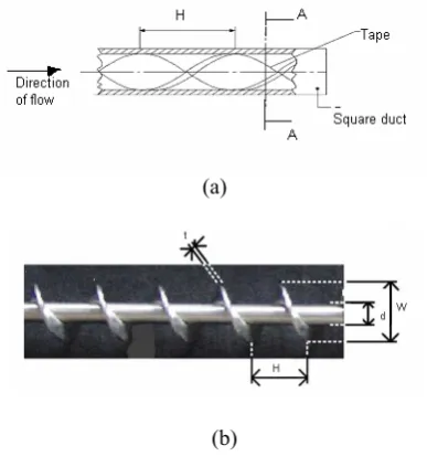
The details of test inserts and experimental set up of a concentric tube heat exchanger (square duct inner and circular annulus outer) are presented in Figs. 1 and 2. The double pipe heat exchanger consisted of two concentric tubes; the inner square duct for cold water flow and the outer tube for hot water flow. The diameters of the inner and outer tubes were 21.41 and 56mm, respectively. The tubes were 2000mm long and 2 mm thick.Copper duct and steel tube were employed for the inner and outer tubes, respectively. The outer tube surface was wrapped with insulation to minimize heat loss to surroundings.
Figs. 1a and 1brepresented the full length twisted tape and full length helical tape insert used in this test. In the experiments, the geometric conditions of the twisted tape and helical tape inserted were kept constant. Twist ratio of twisted tape (y) is defined as the ratio of length of 1800 rotation of twist (H) to the hydraulic diameter (Dh) of duct.
Twisted tape was made of stainless steel strips of thickness 1 mm (t) and width 19 mm, H=86mm.It was fabricated by twisting a straight tape, about its longitudinal axis, while being held under tension, this was done with the help of lathe
.
Twist ratio of Screw tape (Y) is defined as the ratio oflength of one twist to the diameter of twist. The helical tape was made of stainless steel and has the geometric dimensions of W = 18 mm, d = 8mm, t = 1mm.
(a)
(b)
Fig. 1 Schematic diagram of different inserts, (a) for twisted tape , (b) for Screw tape insert
Fig. 2 Schematic diagram of experimental set up
III. EXPERIMENTAL PROCEDURE
In the experiments, heater was switched on for hot water tank and heated until the temperature reached 60 °C. Then, the centrifugal pump was switched on, and water flow rate to the test section was adjusted using by-pass valve, and test fluid flow rate was varied from (0.1 x 10⁻³ m 3/min to 2.5 x
10-3 m 3/min) through a Rota meter and the inner square tube
of a double pipe heat exchanger. The hot water at 0.40 Kg /sec is allowed to flow through jacket side to maintain constant wall temperature condition.
Steady state was attained within 1 hour for first run, and 20 minutes for subsequent runs. Temperatures of the inlet and outlet of the cold and the hot waters were recorded throughout the experiments and Isothermal pressure drop
was also measured by U-tube inclined manometer using ccl4
plain square duct, with full length twisted tape(y=4)and full length Screw tape insert with centered core rod(Y=4) respectively. Twisted tape was inserted within duct at angle of 450 for maximum utilization of swirl effect.
IV. HEAT TRANSFER CALCULATIONS
The heat transfer rate in the test section was calculated as
)
(T2 T1
C m
Qc = c pc −
(1)
The heat transfer from hot water was calculated as
)
(T3 T4
C m
Qh = h ph − (2)
The average heat transfer was calculated as follows
) (
5 .
0 c h
avg Q Q
Q = + (3)
( )
T ln A hQavg = i i Δ (4)
Under constant wall temperature, the heat transfer rate was calculated as
( )
T ln AQ h
i avg
i= Δ (5)
L D
Ai =4 h (6)
( )
ΔTln=(
(
Tw−T1) (
−Tw−T2)
) (
ln(
Tw−T1) (
Tw−T2)
)
(7)
Mean bulk temperature (Tb) was calculated as
(
)
2
2
1 T
T
Tb= + (8)
∑
= wall 8
w T
T (9)
Where Twall is the local wall temperature evaluated at outer
wall surface of duct.
The internal convective heat transfer coefficient hi was
calculated by substituting Eqs.(4),(6)and (7) in Eq.(5) and Nusselt number was calculated as
k D h
Nu= i h (10)
All thermo physical properties of fluid were determined at mean bulk temperature from Eq.(8)
Percentage heat loss in the heat transfer experiments Were calculated as
% heat loss =
(
(
Qh−Qc)
/Qh)
*100 (11)heat loss, is found to be 6-8%, to the surrounding.
V.PRESSURE DROP CALCULATION
The pressure drop was calculated using vertical inclined U–tube manometer. The fully developed friction factor was calculated from following equation
⎟ ⎟ ⎠ ⎞ ⎜ ⎜ ⎝ ⎛ ⎟ ⎠ ⎞ ⎜ ⎝ ⎛ Δ
= 2
2 V
D
L p
f h
ρ (12)
Where ∆P in pressure drop across length L
The uncertainty in the data calculation was based on Steel and Coleman [5] and Kline and McClintock [6]. The maximum uncertainties of non-dimensional parameters were ± 6 % for Nusselt number and ±11% for friction factor and ± 5% in Reynolds number respectively. The uncertainty in the mass measurement has corresponding estimated uncertainty of ±4%.The experimental results obtained were reproducible within these uncertainty ranges.
VI. RESULT AND DISCUSSION
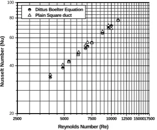
Comparison between the present experimental work and correlation from the previous work of plain square duct for turbulent flow in order to standardize experimental set up are presented in Figs. 3 and 4.
A. Validation of experimental set up
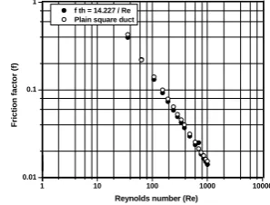
The results obtained during experimental investigations are presented and discussed in this section. Fig. 3 shows laminar flow, isothermal friction factor for the plain duct were Compared with analytical equation, f =14.227/Re (both
f and Re defined on the basis of hydraulic
diameter).Experimental data of friction factor are matching with ± 5%.discripancy.
1 10 100 1000 10000
0.01 0.1 1
f th = 14.227 / Re Plain square duct
Fr
ic
ti
on f
a
c
tor
(
f)
Reynolds number (Re)
Fig. 3 Data verification of friction factor of plain duct
B. Heat transfer result
2500 5000 7500 10000 12500 1500017500 20
40 60 80 100
Dittus Boelter Equation Plain Square duct
N
u
ss
el
t N
u
m
b
er
(
N
u
)
Reynolds Number (Re)
Fig. 4 Data verification of Nusselt number of plain duct
C. Heat transfer and Friction factor
Variation of Nusselt number and friction factor with Reynolds number for the Square duct fitted with helical screw insert and full length twisted tape are shown in Figs. 5
and 6.By referring Fig.5 presents that friction factor
decreases with the increasing Reynolds number. As expected, the friction factor obtained from the duct with the twisted tape and helical screw-tape is significantly higher than that from the plain duct. The friction factor for the duct with the helical screw-tape is substantially higher than that for the twisted tape because of a higher surface area. Due to higher swirling flow or turbulence flow and long residence time in the duct. Also, the flow velocity is larger since the motion is not in an axial direction. Results of the
1 10 100 1000 10000
1E-3 0.01 0.1 1 10
Twisted tape
Screw tape
plain duct
F
ric
ti
o
n
f
act
o
r
(f)
Reynolds number(Re)
Fig. 5 Variation of friction factor with Reynolds number
Isothermal friction factor for the present twisted tape and helical screw-tape are higher than those for the plain duct around 7.7 times and 14 times respectively From Fig. 6 one can observe that the inner duct containing the twisted tape and helical screw tape with core-rod gives higher heat transfer rate than that of the plain duct. Furthermore, the swirl enhances the flow turbulence, leading to even better convection heat transfer. Thus, the higher the Reynolds number is, the greater the heat transfer rate. This can be attributed to swirling effect created from the use of the helical screw-tape, causing higher temperature and pressure gradients in the radial direction. Due to the swirl flow or high tangential velocity component and lower flow
cross-sectional area, the mixing of fluid between fluid at the wall region and fluid at the core region induced by the generated centrifugal force has significant ability to enhance heat transfer rate. Over entire investigated laminar range, mean Nusselt number for the present twisted tape and helical screw tape are higher than those for the plain duct around 2.85 times and 5.3 times respectively.
1 10 100 1000 10000
1 10 100
Twisted tape Screw tape Plain square duct
Nuss
e
lt
number
(
N
u)
Reynolds number(Re)
Fig. 6 Variation of Nusselt number with Reynolds number
VII. THERMAL PERFORMANCE RATIO
The performance ratios R1 and R3 were then calculated
using equations (13) and (14) respectively, based on actual experimental data for Nua. [3]
(
)
h D T T N L m
a Nu
Nu
R1 0 , , , , ,
1
Δ
= (13)
h D T T N L P o a Nu
Nu
R3=( ) , , ,Δ ,1, (14)
Variation of Thermal performance ratios with augmented Reynolds number (Rea) for full length twisted tapes and full
length screw tape insert with core rod are presented in Fig.7.
The thermal performance ratio (R1 at constant flow rate)
increases with increasing Reynolds number for both types of inserts. For twisted tape insert, after a Reynolds number of about 1205, and for screw tape insert after Reynolds number of 1907, the R1values decline sharply. R1 Values decreases
due to appearance of turbulence in transition region; this
may leads to increased value of Nuo. Maximum performance
yields 3.49 and 6.57times the plain square duct for twisted tape and screw tape insert respectively, at corresponding Reynolds number of 1205 and 1907.
On constant pumping power basis, thermal hydraulic performance ratio R3 increases with increase in Rea, for both
types of inserts. Maximum performance yields 2.81 and 3.52 times the plain square duct for twisted tape and screw tape insert respectively at corresponding Reynolds number of 1009 and 752. Further increase in Rea, declines R3 sharply.
At high flow rate, R3 values reaching below 1.0.This happen
due to fact that for corresponding values of Rea, equivalent
plain duct Reynolds number becomes more than 2100 then values of Nuo were found higher, thus reducing performance
0 1 2 3 4 5 6 7 8 9
0 500 1000 1500 2000 2500
Rea
R1,
R
3
R1 for tw isted tape R3 for tw isted tape R1 for screw tape insert R3 for screw tape insert
Fig.7 Variation of Thermal performance ratio with augmented Reynolds number
VIII. CONCLUSION
Experimental work has been carried out to provide the heat transfer and isothermal friction factor data in a Square duct under constant wall temperature condition containing the twisted tape and helical screw-tape with core-rod inside The helical screw-tape insert not only has a significant effect on, enhancing heat transfer rate but also considerable increase of friction factor. It is apparent that the heat transfer rate from using the helical screw-tape with core- rod is higher and observed around 3.52 and 6.57 times the plain square duct at constant pumping power and constant flow rate respectively.
NOMENCLATURE
0
A plain duct flow cross sectional area, (W.D), m2
P
C specific heat at constant pressure, KJ Kg.K
d Diameter of core rod of screw tape insert ,mm
D depth of duct cross section, mm
h
D hydraulic diameter of square duct
=4A0 2(W+D), mm
0
D outside diameter of duct, mm
1
D inner diameter of annulus, mm
f fanning friction factor, dimensionless
g acceleration due to gravity, m2/s
i
h average convective heat transfer coefficient,W/m2
oC
h
Δ differential height of vertical manometer, mm
H axial distance for 180o rotation of the tape, mm
k thermal conductivity of the test liquid, W/m.k
L length of test section, m
c
m mass flow rate of cold liquid, Kg/s
h
m mass flow rate of hot liquid, Kg/s
N number of heat transfer tubes
Nu Nusselt number (defined on hydraulic
diameter),Nu =hiDh k, dimensionless
a
Nu augmented Nusselt number, dimensionless
0
Nu equivalent plain duct Nusselt
number, dimensionless
P pumping power, kW
P
Δ pressure drop across test section, Δh
(
ρm−ρ)
g, N/m2Pr Prandlt number, CPμ k, dimensionless
c
Q heat transfer rate of cold water, kW
h
Q heat transfer rate of hot water, kW
Q average heat transfer rate, kW
e
R Reynolds number (based on hydraulic
diameter),DhVρ μ, dimensionless
a
Re augmented Reynolds number, dimensionless
0
Re equivalent plain duct Reynolds number,
dimensionless
1
R thermal performance ratio,(Nua Nu0), on constant
mass flow rate, dimensionless.
3
R Thermal performance ratio,(Nua Nu0), on constant
Pumping power, dimensionless.
R differential height of inclined manometer, mm
1
T temperature of test liquid at inlet of test section,
oC
2
T temperature of test liquid at outlet of test section,
oC
3
T temperature of hot liquid at inlet, oC
4
T temperature of hot liquid at inlet, oC
w
T average wall temperature of the duct, oC
V average velocity of test liquid, m/s
y twist ratio of the twisted
tape,
(
H Dh)
,dimensionlessY twist ratio of the screw tape insert, (length of 3600 rotation of tape to the diameter of twist)
dimensionless.
W width of duct, as well as insert , mm
Greek symbols
m
ρ density of manometer fluid, Kg/m3
ρ density of test of liquid, Kg/m3
μ viscosity of test liquid, Kg/m.s
ACKNOWLEDGEMENT
This work was done by Mr. S.V.Patil (Research Scholar) as a part of his doctoral programme during July 2007 to July 2010, at the department of Chemical Engineering, Dr.Babasaheb Ambedkar Technological University, Lonere, under the guidance of Professor P.V.Vijaybabu. We are thankful to the authorities at Dr.BATU; for providing all facilities for completing this work.
REFERENCES
[1] S. Eiamsa-ard, P. Promvonge, “Enhancement of heat transfer in a tube with regularly-spaced helical tape swirl generators”,
Solar Energy, Vol. 78, pp. 483–494, 2005.
[2] P. Sivashanmugam, S. Suresh, “Experimental studies on heat transfer and friction factor characteristics of laminar flow through a circular tube fitted with helical screw-tape
inserts”,Applied Thermal Engineering, vol.26, pp. 1990–
1997, 2006.
[3] S.K. Agarwal, M. Raja Rao, “Heat transfer augmentation for the flow of a viscous liquid in circular tubes using twisted
tape inserts”, Int. J. Heat Mass Transfer, Vol. 39,pp. 3547–
[4] Saha,S.K ,Mallick D.N.,“Heat Transfer and Pressure Drop Characteristics of Laminar Flow in Rectangular and Square Plain Ducts and Ducts With Twisted-Tape Inserts”,
Transaction of ASME , Journal of Heat Trasfer, vol. 127,pp.
966-977, 2005.
[5] W.G. Steele, H.W. Coleman, “Experimental and Uncertainty
Analysis for Engineers”, Wiley, New York, 1989..
[6] Kline, S. J., and McClintock, F. A., “Describing Uncertainties
in Single Sample Experiments,” Mech. Eng., (Am. Soc.