SHEAR-FLEXURAL INTERACTION IN ANALYSIS OF
REDUCED WEB SECTION BEAMS USING
VM LINK ELEMENT
S. Erfani, M. T. Kazemi*
Department of Civil Engineering, Sharif University of Technology P.O. Box 11365-9313, Tehran, Iran
[email protected] - [email protected] *Corresponding Author
(Received: July 13, 2006 - Accepted: March 18, 2007)
Abstract Reduced web section beams in shear-yielding moment-resistant steel frames are used for energy dissipating of earthquakes. The finite element analysis indicates that failure mode of these beams are governed by the combination of shear force and flexural moment. Therefore the analysis of frames with reduced web section beams needs consideration of shear-flexural interaction in those sections. In the present paper, modeling and analysis of reduced web section beams are investigated by using a special element which is called VM link element. The elastic and inelastic shear and flexural deformations and tangential stiffnesses in this link element are considered by using the multi-surfaces plasticity concept with dissimilar yield multi-surfaces. The developed VM link element is examined for some reduced web section beams and it is shown that the results have a good agreement with the finite element results.
Keywords VM Link Element, Shear-Flexural Interaction, Multi-Surface Plasticity, Reduced Web
Section Beams
ﻩﺪﻴﻜﭼ
،ﻩﺪﺷﺥﺍﺭﻮﺳﻥﺎﺟﺎﺑﻱﺰﻠﻓﻱﺎﻫﺮﻴﺗ
ﻥﺎﻤﺘﺧﺎﺳﺮﺑﻩﺯﺮﻟﻲﺸﻤﺧﻱﺎﻫﺏﺎﻗﺭﺩ
ﺩﺭﻮـﻣﻱﮊﺮـﻧﺍﮎﻼﻬﺘﺳﺍﻱﺍﺮﺑ
ﻲﻣﻊﻗﺍﻭﻩﺩﺎﻔﺘﺳﺍ
ﺪﻧﻮﺷ
.
ﻥﺎﺸﻧﺩﻭﺪﺤﻣﻥﺎﻤﻟﺍﺵﻭﺭﺩﺮﺑﺭﺎﮐ
ﻦﻳﺍﺓﺪﻨﻫﺩ
ﺮﮕﻨﻟﻭﻲﺷﺮﺑﻱﻭﺮﻴﻧﺐﻴﮐﺮﺗﻪﮐﺖﺳﺍ
ﻲﺸـﻤﺧ
ﺮﻴﻏﺭﺎﺘﻓﺭﺓﻮﺤﻧﺮﺑ
ﺎﻫﺮﻴﺗﻦﻳﺍﮏﻴﺘﺳﻻﺍ
ﻢﮐﺎﺣ
ﺮﺑﺎﻨﺑﻭﻩﺩﻮﺑ
ﻅﺎﺤﻟﻦﻳﺍ
ﻲﺷﺮﺑﻱﻭﺮﻴﻧﺶﻨﮐﺭﺪﻧﺍﻥﺩﺮﮐ
-
ﺮﮕﻨﻟ
ﻲﺸـﻤﺧ
ﻲﻣﻱﺭﻭﺮﺿﻲﻳﺎﻫﺮﻴﺗﻦﻴﻨﭼﻞﻴﻠﺤﺗﺭﺩ
ﺪﺷﺎﺑ
.
ﻝﺪﻣ،ﺮﺿﺎﺣﺔﻟﺎﻘﻣﺭﺩ
ﺯﺍﻩﺩﺎﻔﺘـﺳﺍﺎـﺑﺎـﻫﺮﻴﺗﻉﻮﻧﻦﻳﺍﻞﻴﻠﺤﺗﻭﻱﺯﺎﺳ
ﻂﺑﺍﺭﻥﺎﻤﻟﺍﻡﺎﻧﻪﺑﻱﺍﻩﮋﻳﻭﻥﺎﻤﻟﺍ VM
ﻲﻣﺭﺍﺮﻗﻲﺳﺭﺮﺑﺩﺭﻮﻣ
ﺩﺮﻴﮔ
. ﻲﺷﺮﺑﮏﻴﺘﺳﻻﺍﺮﻴﻏﻭﮏﻴﺘﺳﻻﺍﻱﺎﻫﻞﮑﺷﺮﻴﻴﻐﺗ
ﺘﺨﺳﻦﻴﻨﭽﻤﻫﻭﻲﺸﻤﺧﻭ
ﻱﺭﻮـﺌﺗﺭﺩﻪـﻧﺎﮔﺪﻨﭼﻢﻴﻠﺴـﺗﺡﻮﻄـﺳﺓﺪـﻳﺍﺱﺎـﺳﺍﺮﺑ،ﻥﺎـﻤﻟﺍﻦـﻳﺍﺭﺩﻲـﺳﺎﻤﻣﻱﺎـﻫﻲ
ﻲﻣﻊﻗﺍﻭﻅﺎﺤﻟﺩﺭﻮﻣﻪﺑﺎﺸﺘﻣﺮﻴﻏﻢﻴﻠﺴﺗﺡﻮﻄﺳﺯﺍﻩﺩﺎﻔﺘﺳﺍﺎﺑﻭﻪﺘﻴﺴﻴﺘﺳﻼﭘ
ﺪﻧﻮﺷ
. ﺓﺪـﺷﻩﺩﺍﺩﻪﻌﺳﻮﺗﻂﺑﺍﺭﻥﺎﻤﻟﺍ VM
ﺵﻭﺭﺯﺍﻞـﺻﺎﺣﺞﻳﺎـﺘﻧﺎـﺑﻪﻠﺻﺎﺣﺞﻳﺎﺘﻧﻭﻩﺪﺷﻩﺩﺎﻔﺘﺳﺍﻩﺪﺷﺥﺍﺭﻮﺳﻥﺎﺟﺎﺑﻱﺎﻫﺮﻴﺗﺯﺍﺩﺭﻮﻣﺪﻨﭼﻱﻭﺭﺮﺑ
ﻥﺎـﻤﻟﺍ
ﻲﻣﻪﺴﻳﺎﻘﻣﺩﻭﺪﺤﻣ
ﻲﻣﻩﺪﻫﺎﺸﻣﺎﻫﻥﺁﻦﻴﺑﻲﺑﻮﺧﻕﺎﺒﻄﻧﺍﻪﮐﺩﻮﺷ
ﺩﺩﺮﮔ
.
1. INTRODUCTION
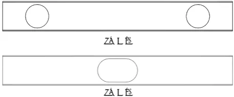
Reduced web section beams in shear-yielding moment-resistant steel frames have been studied in recent researches [1]. These beams are used in steel frames for energy dissipating by shear yielding of their reduced webs. In Figure 1, two common types of these beams are shown. In type (a), near both ends of the beam, the web has been reduced. This type is usually used in frames with a small gravity load and the frames mainly resist lateral seismic loads. In these frames, the reduction of the beam’s web close to the ends does not affect
their ability to resist the gravity loads and the reduced section part could dissipate the earthquake energy demand by yielding. In type (b), the beam’s web is reduced in the middle region. This type can be used in frames in which the gravity load is considerable. In these frames the gravity’s shear force is usually small in the middle and so the web section may be reduced.
shear-flexural interaction in the reduced web zones. The VM link element, which was developed by Kazemi and Erfani [2] to model shear-flexural interaction could be employed for the reduced web zones, too. Kazemi and Erfani [2,3] examined the VM link element for modeling and analyzing of some type (a) reduced web section beams (Figure 1-a) and some link elements in eccentrically braced steel frames. Comparison with the finite element results showed the suitable nearness. In this paper, modeling of the beams with the reduced section at the center (Figure 1-b) using the improved VM link element will be presented.
2. INELASTC FRAME ANALYSES Inelastic analysis and design of structures has made a great progress due to the rapid development of computer hardware and software in the recent decades [4-6]. Common approach for modeling of inelastic behavior in the beam elements has been to adopt inelastic hinge formation at the beam's critical sections. A generalized plastic hinge, with zero length, accounting for interaction for axial, torsional and biaxial bending moments, based on multi-surfaces plasticity concept was presented by Powell and Chen [7]. By using a piecewise linearized yield surface and linear kinematic hardening rule for concentrated hinges, Krenk et al. [8] developed a formulation for displacement discontinuities with extension and rotation components. A method for the modeling of members with yielding under combined flexure and axial force in steel frames subjected to earthquake ground motions was presented by Kim and Engelhardt [9]. Their method has the capability of modeling plastic axial deformation and changes in the axial stiffness, based on isotropic and kinematic strain-hardening defined in axial-flexural space. Liew et al. [10-12] used the two-surface plasticity concept for considering the inelastic interaction between axial force and bending moment, too.
To consider the shear-flexural interaction, Ricles and Popov [13] developed a formulation for modeling links in the eccentrically braced steel frames (EBFs), based on multi-surfaces plasticity concept. The link beam had a nonlinear
hinge at each end, which consisted of uncoupled shear and flexural nonlinear subhinges. The finite element method for modeling of the shear-flexural inelastic zones could also be used, but it may take extensive time and is not applicable. Saritas and Filippou [14] investigated the shear-flexural interaction in the link beams by using a displacement field based on Timoshinko's beam theory and integration of the biaxial stress-strain relations over several control sections along the beams. Each control section subdivided into several layers. This method is a general way of considering axial, shear and flexural interaction in the frames. Although predicted behavior shows a good accuracy, because of integration in several points, it is time consuming. Kazemi and Erfani [2,3,15] proposed the VM link element for use in frames where shear-flexural interaction should be considered. The element can be used in any arbitrary location of the frames and may have zero or a nonzero length. The multi-surface concept with dissimilar yield surfaces was adopted. In the present paper, a new improved revision of the VM link element is briefly described and is employed for modeling of the reduced web section beams type b (Figure 1-b).
3. DEFINITION OF THE VM LINK ELEMENT
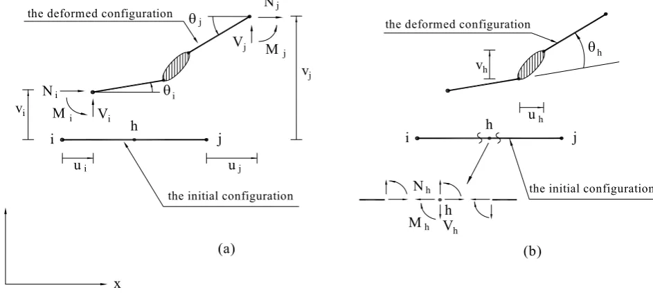
The introduced VM link element includes one inner inelastic hinge with zero length and two rigid beams with zero or nonzero lengths in two sides of it. As seen in Figure 2, i and j are the outer nodes and h is the inner hinge which has an arbitrary location. The lengths of the two rigid parts are Li and Lj, and L = Li + Lj is the total length of the element. The inelastic zones of beams could be modeled by this link element.
If the link's end forces and displacements are described as column matrixes of P and U, respectively (see Figure 3a) and the element's internal forces and deformations in the inner inelastic hinge are defined as column matrixes of Ph and Uh, respectively (see Figure 3b). Then one could express:
h AP
U T A h
U = (2)
where A is the transformation matrix, which its components depend only on the lengths of the rigid parts of the link and are as follows:
⎥ ⎥ ⎥ ⎥ ⎥ ⎥ ⎥ ⎥ ⎦ ⎤ ⎢ ⎢ ⎢ ⎢ ⎢ ⎢ ⎢ ⎢ ⎣ ⎡ − − − − − = ⎥ ⎥ ⎦ ⎤ ⎢ ⎢ ⎣ ⎡ = 1 j L 0 0 1 0 0 0 1 1 i L 0 0 1 0 0 0 1 j Ai A
A (3)
It is assumed that no loads or masses are assigned to the hinge and to the rigid parts except at the end nodes. The element's tangential stiffness matrix K can be related to Kh and Fh as:
T A 1 h AF T A h AK
K= = − (4)
where Kh and Fh are the tangential stiffness and
flexibility matrixes of the inner hinge, respectively.
4. INNER HINGE'S FLEXIBILITY AND STIFFNESS
If the rates of forces and deformations in the element's inner hinge are shown as P&h and U&h, respectively, then one could write:
h U h K h
P& = & (5)
The components of Kh can be obtained by inversing the inner hinge's tangential flexibility matrix, Fh. For the small deformation, Fh can be decomposed as: p h F e h F h
F = + (6)
where Fhe and Fhp are the inner hinge's elastic and plastic tangential flexibility matrixes, respectively. The components of Fhe may be obtained from the classic formulas and Fhp is assumed as:
p M h F M p V h F V p h
F = ϕ +ϕ (7)
In which FhVp and FhMp are the flexibility matrixes related to the pure shear and the pure flexural loadings, respectively. ϕV and ϕM are arbitrary functions satisfying the conditions of
0 M 1,
V= ϕ =
ϕ for the pure shear loading and
1 M , 0
V= ϕ =
ϕ for the pure flexural loading. In the present study, ϕV and ϕMare supposed as:
) ) 2 V m 1 ( ) 1 v a ( 1 ( 2 V m
V= + − −
ϕ (8)
) ) 2 M m 1 ( ) 1 m a ( 1 ( 2 M m
M = + − −
ϕ (9)
where mV and mM are the components of m vector, TYPE (a)
TYPE (b)
Figure 1. Two common types of reduced web section beams.
i h j
L
i j
L
L
which is the unit location vector of the action point in VM space (See Figure 4). The aV and aM are constant parameters which depend on the joint geometry, size and material. Using them, the flexibility may be decreased through combining of shear and flexure. The results of the experimental studies or the numerical analyses may be used for determination of FhVp , FhMp , aV and aM. In the current paper, they are obtained through using the finite element analysis.
Equation 7 implies that the flow rule is not associated. For non-associated plasticity, to differentiate between plastic flow and elastic unloading, the loading-unloading criteria need to be defined more precisely. Suppose the action point lies on a yield surface and the deformation rate is U&h. The first step is to take Kh=(Fhe)−1, the action rate P&h is then predicted. If the condition λ1=nTP&h<0 was observed, it means that we have unloading and for the condition
0 1=
λ , the natural loading is governed.
For the corner points, these conditions for
both nB and nC should be satisfied. nB and nC are the unit normal vectors at points B and C, which are very close to the corner, but on two different surfaces (see Figure 4).
If the condition λ1>0 was encountered, using
1 ) p h F e h F ( h
K = + − , the new action rate P&h is calculated using Equation 5. With the new P&h, if the condition λ2 =nTP&h >0 is reached, the plastic loading condition will govern. For the corner point, plastic loading condition needs to be satisfied only for one of the unit vectors, nB or
C
n . If λ2≤0, the stiffness matrix will be adjusted to:
1 ) e h F ( 1 2 1 ) p h F e h F ( h
K −
λ λ − − +
= (10)
By using the adjusted stiffness and calculating the new action rate P&h (normality condition) nTP&h =0
will reach and the natural loading conditions will govern.
j θ
j u
j v θi
Mj Vj
j N
i
i i
M V
N
i h j
x
y the initial configuration
the deformed configuration
ui vi
h u h
v
θh
h
h h
M V
N
i h j
the initial configuration the deformed configuration
(a) (b)
h
o
m
M
V
B C
n
m
A D
n
CC
B B
Figure 4. The normal and location vectors at a corner point.
O
V
M
V M
V M
yi yj yi
yj
Vsi Vsj
Msi Msj
k l
h h
Figure 5. Polygonal dissimilar yield surfaces.
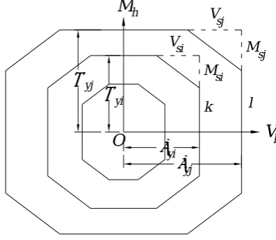
5. YIELD SURFACES
For considering interaction between the shear force and flexure, the multi-surface concept in shear-flexural space is used (see Figure 5). This concept, which was originally defined in stress space [16,17], was adapted with some modifications for the resultant forces space for the frame elements [7-14].
It is assumed that the yield surfaces are convex and could be translated and changed in size. They could not be intersected, but could be tangential to each other. If the action point is in the internal part of initial yield surface, the behavior will be elastic and if it is on each of the surfaces, the behavior will be elastoplastic. In tangency of several yield surfaces, the outer surface properties define the
current behavior. The similarity assumption among yield surfaces has been used in most works in regard to having parallel normal directions for the corresponding points on the yield surfaces. If it is assumed in the shear-flexural space that the yield surface i is similar to the yield surface j, then we will have:
yj M
yi M
yj V
yi V
= (11)
where Vyi, Vyj, Myi and Myj are the points on i and j yield surfaces for the pure shear and flexural loadings. In general, this may not be a suitable assumption and the pure flexural yielding is very different from pure shear yielding. In the present research, with dissimilar polygonal yield surfaces shown in Figure 5, the shear-flexural interaction is considered more realistically. To prevent intersection of the yield surfaces, the corresponding sides of all yield surfaces should be parallel with each other and the length of any side of any yield surface should be smaller than the length of the corresponding side of the next outer yield surface. For the yield surfaces presented in Figure 5, the conditions of Vsi≤Vsj, Msi≤Msj,
sj V yj V si V yi
V − ≤ − , and Myi−Msi ≤Myj−Msj
must be ensured. Also, in order to keep parallel the corresponding sides of the yield surfaces with each other, we should have:
sj Msi M
sj Vsi V
= (12)
6. HARDENING RULE
i + 1
i
h i + 1
h i P
P Ph
h P
Figure 6. Action point and corresponding points on two
adjacent yield surfaces.
implemented, too.
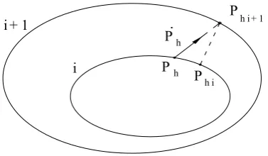
For managing the yield surfaces, the kinematic hardening rule, which was recently proposed by Kazemi and Erfani [2,3] is used. The i-th yield function is defined as:
0 ) i
α
h P (
i − =
φ (13)
where Ph is the action vector of the inner hinge and αi is the i-th yield function center. If the action location is on the i-th yield surface and plastic loading occurs, the rate of i-th yield surface translation, α&i, may be defined as:
μ − +
= &
&i (Phi 1 Phi)
α (14)
where, Phi+1 is the intersection point between the direction of the action rate, P&h, and (i+1)-th yield surface. The term Phi is the conjugate point of
1 hi
P + on i-th yield surface (see Figure 6).
By this definition, when the action point, Ph, approaches closer to (i+1)-th yield surface, i-th yield surface moves, in a way that the two points on the i-th yield surface, Phi and Ph, approach closer to each other and coincide with Phi+1, asymptotically. Then the inner moving yield surface may be tangential to the outer yield surface at the contact point and they never intersect. To calculate μ&, plastic loading
condition (φ&i=0) is used, hence:
) hi P 1 hi P ( h P
i
h P h P
i
− + ∂
φ ∂
∂ φ ∂
= μ
&
& (15)
By substituting Equation 15 in Equation 11, α&i can be demonstrated that:
) hi P 1 hi P ( ) hi P 1 hi P ( h Pi
h P h Pi i
α + −
− + ∂
φ ∂
∂ φ ∂
=
&
& (16)
i
α& is the translation rate for i-th yield surface, due to loading
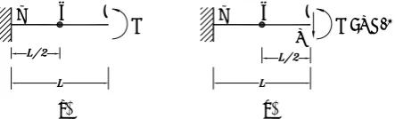
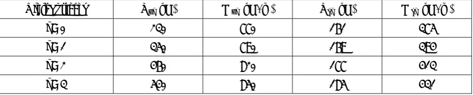
7. REDUCED WEB SECTION BEAM A reduced web section beam as shown in Figure 7 is investigated. The beam consists of W21× 68 section (A = 13131 mm2, I = 625770000 mm4, and As = 5900 mm2 ) with the span length of 4000 mm and only one hole at the center, where A, I and As are the area, the moment of inertia and the shear area of the beam section. The geometry of the hole is presented in Figure 7. Multi-linear kinematic hardening plasticity is assumed for the material of the beam, with Fy = 360 MPa, Fu = 500 MPa, E = 200 GPa, H = 0.005E and ν = 0.3, where Fy and Fu are the yield and ultimate stress, E and H are the initial and the post yield moduli and ν is the Poisson ratio, respectively.
For the modeling of the central part of the beam, a VM link element with length of L = 1260 mm is used. Location of the inner hinge is assumed in the middle of the VM element (Li = Lj = 630 mm), coinciding with the center of the hole, as shown in Figure 8.
beam element VM element beam element
inner hinge
Figure 8. Modeling of the reduced web section beam with
beam and the VM link elements.
i h j M i h j M=VL/2
V
(a) (b)
Figure 9. Boundary conditions and loadings of the VM link
element for (a) pure flexural and (b) pure shear.
the pure flexural loading, the shear force is zero at the hole's center (see Figure 9).
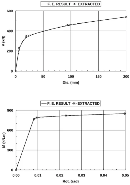
The analyses are performed by the nonlinear finite element software, ANSYS, using solid element SOLID45. The Results are presented in Figure 10, where extracted yield points are shown.
In the figures, the horizontal axes indicate the displacement and rotation of the right end. Based on the results, the yield surfaces for the inner hinge are simplified as shown in Figure 11 and Table 1. The inner hinge flexibility matrixes in between the two consecutive yield surfaces may be calculated as:
j A jj F T
j A * h
F = (17)
Where Aj defined from Equation 3 with assumption of Lj = 630 mm and Fjj is the element at node j as follows:
⎥ ⎥ ⎥ ⎥ ⎥ ⎥ ⎥ ⎥ ⎥
⎦ ⎤
⎢ ⎢ ⎢ ⎢ ⎢ ⎢ ⎢ ⎢ ⎢
⎣ ⎡
+ =
EI L
4 r
1
4 k
1 2EI
2 L
3 r
1
3 k
1 0
2EI 2 L 3 r
1 3 k
1 s GA
L 2 r
1 2 k
1 3EI
3 L 1 r 1 1 k
1 0
0 0
EA L
0 r
1
jj F
(18)
r0, r1, r2, r3, and r4 are the equivalent effective stiffness factors. From the finite element analysis the values of 0.862, 0.955, 0.108, 0.955, and
53
6 mm
4000 mm
420
mm
210mm210mm 210mm
0.955, are obtained, respectively. k1, k2, k3 and k4 are the hardening coefficients. If we assume that
k1 = k2 = k3 = k4 = 1, the Fh* will change to Fhe, and if the coefficients are selected as appropriate value for pure loadings, as presented in Table 2, the Fh* will change to FhVp or Fhmp . After the calculation of Fhe, FhVp and Fhmp , using Equations 17 and 18, the total flexibility matrix, Fh, is obtained from Equations 6 and 7. For definition of the aV and aM, used in Equation 7, combined shear force and flexural moment at the inner hinge location should be applied. The middle part of the beam was reanalyzed by the finite element method for a combined loading and the aV and aM were resulted, as shown in Table 2.
8. INELASTIC ANALYSIS USING VM LINK ELEMENT
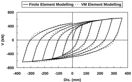
The beam shown in Figure 7 is analyzed for three different boundary conditions and loadings. The analyses are performed using the finite element method (ANSYS software), and VM link element modeling, and their main results are compared. In the first example, rotational freedoms at the both ends are prevented and the right end of the beam is subjected to a cyclic displacement, as shown in Figure 12. The shear force at the inner hinge location resulted from the finite element method and VM link element modeling is compared in Figure 13. As seen, the results have excellent agreement with each other. It is noted that, the flexural moment at the inner hinge location is zero in this case and the shear yielding is the governing mode.
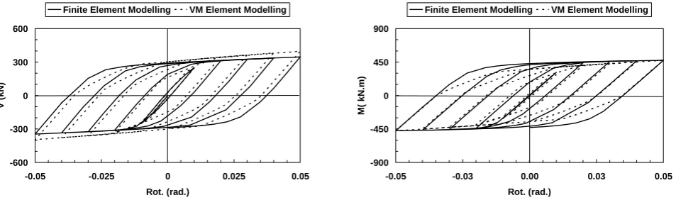
In the second example, the rotational freedom at the right end of the beam is released and the right end of the beam is subjected to a cyclic displacement, as shown in Figure 12. The comparison between the finite element method and the VM link element modeling are presented in Figure 14. As seen, the results have a good agreement with each other.
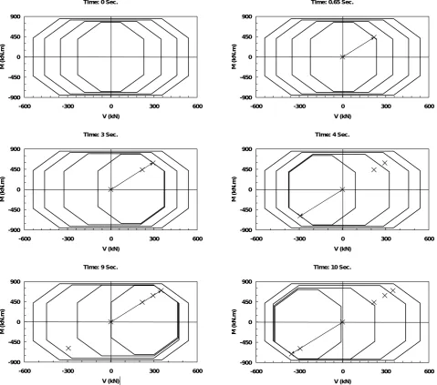
The translation of yield surfaces for the inner hinge of the VM link element is shown in Figure 15. As seen, the action point is located at the shear-flexural interactionzone.
For the third example, the displacement
0 200 400 600
0 50 100 150 200
Dis. (mm)
V (
k
N
)
F. E. RESULT EXTRACTED
0 300 600 900
0.00 0.01 0.02 0.03 0.04 0.05
Rot. (rad)
M (
k
N.m)
F. E. RESULT EXTRACTED
Figure 10. Finite element results and extracted yield points in
pure loadings.
V M
0 1 2 3
Ms3 V s3
y0
V Vy1 Vy2 Vy3
My0
My3
freedom at the right end of the beam is prevented and the right end of the beam is subjected to a cyclic rotation, as shown in Figure 16. The comparison between the reseults of finite element method and the VM link element modeling is presented in Figure 17. As seen, the results have fairly good agreement with each other. The translation of yield surfaces for the inner hinge of the VM link element is shown in Figure 18. As seen, the shear yielding is governed, at the beginning, but later the action point moves to the shear-flexural interaction zone. Comparison of the results in the three cases yielded that, although the failure modes are different, the VM link element modeling has good accuracy.
9. CONCLUSIONS
In this paper, analysis of the reduced web section beams was investigated. The reduced web section beams are used for earthquake energy
dissipation in shear-yielding moment-resistant steel frames. The shear-flexural interaction in the reduced web zones was modeled by the proposed VM link element. The elastic and inelastic shear and flexural deformations and tangential stiffnesses in this element, are considered by using the multi-surfaces approach with dissimilar yield surfaces. The VM link element was examined for some reduced web section beams and it was shown that the results of analysis using VM link element, which requires less computer time, have good agreement with the finite element results.
10. REFERENCES
1. Halterman, A. and Aschheim, M., “Analytical Studies of Shear-Yielding Moment-resistant Steel Frames”, 12th
World Conference on Earthquake Engineering,
Auckland, New Zeeland, Paper No. 1544, (2000). 2. Kazemi, M. T. and Erfani, S., “Mixed Shear-flexural
(VM) Hinge Element and It’s Application”, Scientia
TABLE 1. The Inner Hinge Yield Surfaces Parameters.
YieldSurfaces Vyi (kN) Myi (kN. m) Vsi (kN) Msi (kN. m)
i = 0 230 770 161 375
i = 1 350 790 169 394
i = 2 460 820 177 413
i = 3 540 850 185 431
TABLE 2. The Inner Hinge Flexibility Matrixes Parameters.
K1, K2, K3 and K4 aV and aM Between
Yield Surfaces: Pure Shear Pure Flexural Pure Shear Pure Flexural
0 and 1 0.250 0.150 3.0 3.0
1 and 2 0.040 0.024 2.5 2.5
-600 -300 0 300 600
-400 -200 0 200 400
Dis. (mm)
V (
k
N)
Finite Element Modelling VM Element Modelling
-900 -450 0 450 900
-400 -200 0 200 400
Dis. (mm)
M (k
N
.m
)
Finite Element Modelling VM Element Modelling
Figure 14. Comparison of results for the second example.
-400 -200 0 200 400
0 2 4 6 8 10 12
Time (Sec.)
Dis.
(m
m)
Figure 12. Relative displacement applied between two ends of
the first and second example.
-800 -400 0 400 800
-400 -300 -200 -100 0 100 200 300 400
Dis. (mm)
V (
k
N)
Finite Element Modelling VM Element Modelling
Figure 13. Comparison of results for the first example.
Iranica, Vol. 14, No. 3, (2007), 193-204.
3. Kazemi, M. T. and Erfani, S., “VM Link Element for Modeling of Shear-flexural Interaction in Reduced Web Section Beams”, Seventh International Congress on
Advances in Civil Engineering, Istanbul, Turkey,
Paper No. ace 06-131 (2006).
4. Chen, W. F. and Lui, E. M., “Stability Design of Steel Frames”, Boca Raton, Fl: CRC Press, (1991).
5. Mazzolani, F. M. and Piluso, V., “Theory and Design of Seismic Resistant Steel Frames”, E and FN Spon: hampion and Hall, (1996).
6. Jirasek, M. and Bazant, Z. P., “Inelastic Analysis of Structures”, New York, John Wiley and Sons: LTD (2002).
7. Powell, G. H. and Chen, P. F. S., “3D Beam-Column Element with Generalized Plastic Hinges”, ASCE
Journal of Engineering Mechanics, Vol. 112, No. 7,
(1986), 627-641.
8. Krenk, S., Vissing, S. and Vissing, J. C., “A Finite Step
Updating Method for Elastoplastic Analysis of Frames”,
ASCE Journal of Engineering Mechanics, Vol. 119,
No. 12, (1993), 2478-2495.
9. Kim, K. D. and Engelhardt, M. D., “Beam-Column Element for Nonlinear Seismic Analysis of Steel Frames”, ASCE Journal of Structural Engineering,
Vol. 126, No. 8, (2000), 916-925.
10. Liew, J. Y. R. and Tang, L. K., “Advanced Plastic Hinge Analysis for the Design of Tubular Space Frames”, Engineering Structures, Vol. 22, No. 7, (2000), 769-783.
11. Liew, J. Y. R., Chen, W. F. and Chen, H., “Advanced Inelastic Analysis of Frame”, Journal of
Construction Steel Research, Vol. 55, No. 3, (2000),
245-265.
12. Liew, J. Y. R., Chen, H., Shanmugam, N. E. and Chen, W. F., “Improved Nonlinear Plastic Hinge Analysis of Space Frame Structures”, Engineering Structures, Vol. 22, No. 10, (2000), 1324-1338.
13. Ricles, J. M. and Popov, E. P., “Inelastic Link Element for EBF Seismic Analysis”, ASCE Journal of
Structural Engineering, Vol. 120, No. 2, (1994),
Time: 0 Sec.
-900 -450 0 450 900
-600 -300 0 300 600
V (kN)
M (k
N
.m
)
Time: 0.65 Sec.
-900 -450 0 450 900
-600 -300 0 300 600
V (kN)
M (k
N
.m
)
Time: 3 Sec.
-900 -450 0 450 900
-600 -300 0 300 600
V (kN)
M (k
N
.m
)
Time: 4 Sec.
-900 -450 0 450 900
-600 -300 0 300 600
V (kN)
M (k
N
.m
)
Time: 9 Sec.
-900 -450 0 450 900
-600 -300 0 300 600
V (kN)
M (k
N
.m
)
Time: 10 Sec.
-900 -450 0 450 900
-600 -300 0 300 600
V (kN)
M (k
N
.m
)
Figure 15. Translation history of yield surfaces for the inner hinge for the second example.
-0.06 -0.04 -0.02 0.00 0.02 0.04 0.06
0 2 4 6 8 10 12
Time (Sec.)
R
o
t.
(ra
d
.)
-600 -300 0 300 600
-0.05 -0.025 0 0.025 0.05
Rot. (rad.)
V (
k
N)
Finite Element Modelling VM Element Modelling
-900 -450 0 450 900
-0.05 -0.03 0.00 0.03 0.05
Rot. (rad.)
M
( k
N
.m
)
Finite Element Modelling VM Element Modelling
Figure 17. Comparison of results for the third example.
Time: 0 Sec.
-900 -450 0 450 900
-600 -300 0 300 600
V (kN)
M (k
N
.m
)
Time: 0.9 Sec.
-900 -450 0 450 900
-600 -300 0 300 600
V (kN)
M (k
N
.m
)
Time: 3 Sec.
-900 -450 0 450 900
-600 -300 0 300 600
V (kN)
M (k
N
.m
)
Time: 3 Sec.
-900 -450 0 450 900
-600 -300 0 300 600
V (kN)
M (k
N
.m
)
Time: 9 Sec.
-900 -450 0 450 900
-600 -300 0 300 600
V (kN)
M (k
N
.m
)
Time: 10 Sec.
-900 -450 0 450 900
-600 -300 0 300 600
V (kN)
M (k
N
.m
)
14. Saritas, A. and Filippou, F. C., “Modeling of Shear-yielding Members for Seismic Energy Dissipation”, 13th
World Conference on Earthquake Engineering,
Vancover, Canada, Paper No. 1799, (2004).
15. Erfani, S. and Kazemi, M. T., “VM Link Element for Consideration of Shear-flexural Interaction”, The Tenth East Asia Pacific Conference on Structural
Engineering and Construction, Bangkok, Thailand,
Vol. Analytical and Computational Methods, (2006), 149-154.
16. Khan, A. S. and Huang, S., “Continuum Theory of Plasticity”, New York: John Wiley and Sons. Inc. (1995).
17. Mroz, Z., “An Attempt to Describe the Behavior of Metals Under Cyclic Loads Using a More General Workhardening Model”, Acta Mechanica, Vol. 7, No.
2-3, (1969), 199-212.
18. Ramadan, T. and Ghobarah, A., “Analytical Model for Shear Link Behavior”, ASCE Journal of Structural