A Vibration Signal Processing of Large-scale Structural Systems
Based on Wireless Sensor
https://doi.org/10.3991/ijoe.v13i05.7050
Lian Xue
WuHan Technology And Business University, Wuhan, China
Cheng-song Hu
WuHan Technology And Business University, Wuhan, China
Abstract—The inherent characteristics of large-scale structural system are also called modal parameters, which include natural frequency, damping ratio and vibration mode. They are the basis for analyzing dynamic characteristics of large-scale structural system. Modal Parameter Identification is a modern meth-od, and it is used to identify the vibration signals. At present, the problem of large-scale structural system security is paid more and more attention to, so the method of modal parameter recognition is very significant. A fast integral method is put forward to eliminate the trend item of vibration signals, and the vibration signals are collected through the wireless sensor network (acceleration signal), so as to obtain the integrated vibration signal (speed and displacement signal). The polynomial fitting method is applied to eliminate the trend items in the sampling integral, and improve the operation speed and accuracy by the re-lationship among the various coefficients. Then, they are discretized to meet the wireless sensor network requirements of "online" processing and analysis. Through the simulation of acceleration signals based on finite element model-ing and the processmodel-ing of actual acquisition acceleration signals based on wire-less sensor network, the effectiveness of this method was verified. As a result, the precision effect by sampling frequency and the data length is summarized.
Keywords—wireless sensor, large-scale structure, modal parameter identifica-tion
1
Introduction
dis-placement signal acquisition often has many problems, like expensive high precision equipment, sensor installation, difficult on small vibration displacement acquisition and other issues. Therefore, we can use acceleration signal of relative easy acquisi-tion, to obtain the signal of relative difficult acquisition based on the integral relation between acceleration, velocity and displacement [3]. Although the integral relation between them is very clear, in the actual collection process, the sensor will produce zero drift and zero drift is not fixed, which make this problem more complex [4]. Obtaining the more "real" displacement signal through the actual acceleration signal has become the research direction of many scholars.
With the rise of wireless sensor network, the acceleration signal is easily gathered in the condition of high frequency sampling. Through collected acceleration signal to obtain the velocity displacement signal is still an important part in vibration signal processing. The main method is based on frequency domain method and time domain method. How to eliminate the trend item in a large extent is still the main problem. But frequency domain method is easy to cause the truncation error, such as leakage. This phenomenon will occupy more resources because wireless sensor networks need us to analyze and tackle the problem online. Therefore, this paper focuses on the analysis of the causes of errors and how to better eliminate the trend item.
2
State of the art
In summary, it is an important part of the vibration signal processing to obtain the velocity and displacement signals by collecting the acceleration signals. Although there is only a small amount of literature on how to eliminate the trend items, the question of how to improve the speed and accuracy of the operation, how to deter-mine the initial value of velocity and displacement, and how to solve the zero dynam-ic drift is still not solved. Therefore, A fast integral method is put forward to eliminate the trend item of vibration signals, and the vibration signals are collected through the wireless sensor network (acceleration signal), so as to obtain the integrated vibration signal (speed and displacement signal). The polynomial fitting method is applied to eliminate the trend items in the sampling integral, and improve the operation speed and accuracy by the relationship among the various coefficients. Then, they are dis-cretized to meet the wireless sensor network requirements of "online" processing and analysis. Through the simulation of acceleration signals based on finite element mod-eling and the processing of actual acquisition acceleration signals based on wireless sensor network, the effectiveness of this method was verified. As a result, the preci-sion effect by sampling frequency and the data length is summarized.
3
Modal parameter identification
3.1 Vibration displacement signal
Vibration is a common natural phenomenon, and it is the reciprocating motion of objects or structures over time with respect to their equilibrium position. Although the vibration is beneficial, it will influence equipment performance, equipment life and the performance of building and large structure.
Vibration signal processing is to analyze and process the collected data in various ways in order to obtain the required information we need, so as to solve or prevent the related problems caused by vibration based on effective measures.
For nearly 30 years, vibration signal processing has undergone the process of the artificial analysis of analog signal and digital signal processing. The analysis of the vibration signal has developed rapidly on the basis of theory and technology.
With the appearance of structural health monitoring and the development of wire-less sensor networks, more and more data can be obtained from the observed objects in real time, so as to understand the health of the observed objects. However, in many cases, acquisition of certain data is very difficult, even unable be directly measured, thereby other data processing methods should be considered.
precision instruments, the cost is still too high. It is an effective method to obtain the vibration displacement by acceleration signal [7-8]. However, the speed signal and the displacement signal are obtained by the acceleration signal. The acquired acceleration signal is converted to the frequency domain by fast Fourier transform. We integrate the converted acceleration signal in frequency domain based on calculus's properties, so as to obtain speed and displacement signals which belong to frequency domain, then convert it to time domain by Inverse Fourier Transform. The direct current signal of data collection is also can be converted by the signals in frequency domain. The processing of the signal undergoes positive transform and inverse transformation of the transform domain, thereby causing error.
Due to the wide application of wireless sensor networks, the data collection mode is changed to wireless. If the collected acceleration signal can be solved in the time domain, that is, the speed and displacement signals are obtained by accelerating the signal, this method will play a positive role in the health assessment of large-scale structure.
3.2 Modal parameter identification method
1) Frequency domain method
Modal parameter frequency domain identification method [9] is mainly using the measured frequency data or curve, according to the frequency response function mod-al expansion, to solve the system modmod-al parameters. This method mainly includes early single-mode parameter identification method, multi-modal parameter identifica-tion method, nonlinear weighted least squares method and orthogonal polynomial fitting method. Single mode parameter identification method can meet the precision of smaller modal coupling system. Multi-modal parameter identification method is suitable for larger coupling systems. In general, we use the iterative method to com-plete the recognition of all modalities.
2) Time domain method
Modal parameter time domain identification method [10] also is called curve fit-ting method. The theoretical curve is fitted with the measured curve to minimize the error. Including the random decrement technique (RDT) method, the system identifi-cation modal parameter (ibrahim time domain -ITD) method, the least squares com-plex exponential (LSCE) method, the ARMA time series analysis method and the eigensystem realization algorithm (ERA) method.
Random decrement technique is a kind of vibration analysis method developed in the 1970s [11~13]. The ideas are as follows. We collect raw data which has several multiple random signals, remove the random response based on mean sample method, and identify the parameter modal according to the free response. It can rely on the excitation signal and only through the response signal to get the system modal param-eters. The precondition is to make environment excitation signal as a random signal.
the free response augmented matrix, so as to estimate the modal parameters of each order.
Least squares complex exponential method, also known as Prony polynomial method. The basic idea is to use the impulse response signal to identify the modal frequency and modal damping. Because this method is designed for a specific sam-pling point, so it belongs to the local recognition method, and can be identified by structure damage.
ARMA time series analysis method is one of the most commonly used methods in time domain analysis. The basic idea is to use the output-input signal to construct the difference equation and Z transform, so as to establish the equivalent relationship of the vibration equation and the ARMA model, the system function and the ARMA model, and then identify the modal parameters [15]. One of the key questions about this is how to effectively identify the parameters of the ARMA model.
The basic idea of ERA is to construct the Hankel matrix according to the collected system impulse response, and to construct the singularity decomposition of the ma-trix, so as to get the minimum implementation of the system. The system matrix is decomposed by the state matrix of the minimum implementation structure, and the modal parameters of the system are obtained.
3Time-frequency method
The time-frequency method is mainly based on the wavelet transform analysis method. The time domain and frequency domain can be combined by wavelet trans-form. This method is often used for denoising or structural modal and damage identi-fication based on wavelet packet energy spectrum.
4
Time-domain integration error analysis of acceleration signal
In practical engineering, the majority of product signals must not be found with the original function in the original function. With the increasing of digitization degree, the data acquisition mode is changed from wired to wireless, and Newton-Leibniz formula cannot be used directly, so we need to find a simple and effective time do-main integration method.
The signal collected by the wireless sensor network is discrete signals, and we can express it when the sampling frequency is known. Time domain integration is the accumulation of area. There are many methods of time domain integration, including trapezoidal formula, middle rectangle formula, Simpson formula, Newton-Cortez formula, complex trapezoidal formula and so on.
We divide the interval [a, b] into n equal parts,
!
"
#
$
%
&
'
=
=
+
=
k
0
1
n
n
a
b
h
kh
a
x
k,
,
,...,
[
x
k,
x
k+1]
(
k
=
0
,
1
,...,
n
!
1
)
,( )
[
( ) ( )
k k1]
xx 2 f x f x
h dx x f 1 k
k ! + +
"
+,
then
"
( )
!"
( )
!
[
( ) ( )
]
( )
# = + # = + + = =
= + n1
0
k k k1 n
1 n 1 k x x b
a 2 f x f x R f
h dx x f dx x f
I k1
k , and
R
n( )
f
is truncation error.Signals collected through a wireless sensor network are
a
( ) (
k
,
k
=
1
,
2
,...,
n
)
. Sampling frequency isf
s. One integrationa
( )
k
based on the above formu-lav
( ) (
k
,
k
=
1
,
2
,...,
n
!
1
)
is( )
(
)
[
( )
(
)
]
k s R f 2 1 k a k a 1 k v k
v ! ! = + + + , and
then
( ) ( ) ( ) ( )
[
]
ks
R
f
2
1
k
a
k
a
1
k
v
k
v
=
!
+
+
+
+
, ifv
( )
0
=
0
,then
( )
[
( ) ( )
]
1s
R
f
2
2
a
1
a
1
v
=
+
+
,( ) ( ) ( ) ( )
[
]
( ) ( ) ( )
[
]
2 1 s 2 s R R f2 3 a 2 a 2 1 a R f2 3 a 2 a 1 v 2
v = + + + = + + + + ,
( ) (
) ( ) ( )
[
]
( )
( ) ( )
!
!
" = " = " + + + = + + " + " = " 1 n 2 j j s 1 n 2 i 1 n s R f2 n a i a 2 1 a R f2 n a 1 n a 2 n v 1 n v(
) (
)
( )
( ) ( )
s 1 n 2 i f 2 n a i a 2 1 a 1 n v 1 n v!
" = # + + = " $ " .In the one integration
v
!( )
k
, there will be a truncation errorR
k, which means that high precision integral signal is relied one first order of truncation error precision, namely, the impact of accuracy of h and n. At present, digital signal is the main source, and it involves the impact of integral accuracy of sampling frequencyf
s and sampling data length n. We analyze the average error and mean square error in this paper.If
a
( )
t
=
sin
(
0
.
6
!
t
)
, thenv
( )
t
=
"
0
.
6
!
•
cos
(
0
.
6
!
t
)
, from the time domaininte-gration, we can obtain
v
!( )
t
.Mean error is!
"( )
( )
=# " "
"
=
n 11 k
1
1
k
-
f
k
f
1
n
1
AME
, meansquare error is
!
"( )
( )
= # " "
$
%
&
'
(
)
"
=
n11 k
2 1
1
k
-
f
k
f
1
n
1
MSE
.60 80 100 120 140 4
6 8 10 12
Av
era
ge
e
rro
r AM
S
Sampling frequency (Hz) AME curve Fitting polynomial x10-3
Fig. 1. Influence curve of frequency on AMS
The fitting polynomial function isAME 72455 10
( )
f 29662 10( )
f 2 000044098 fs 0028034s 6 3
s
9 . . .
. ! ! + ! ! " ! +
"
= " , and the
influence on MSE is shown as Figure 2.
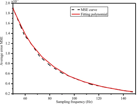
60 80 100 120 140
0.2 0.4 0.6 0.8 1.0 1.2 1.4 1.6 1.8 2.0
A
ver
ag
e er
ro
r M
SE
Sampling frequency (Hz) MSE curve Fitting polynomial x10-4
Fig. 2. Influence curve of frequency on MSE
The fitting polynomial function is
( )
( )
( )
0010081 0
f 10 9639 2
f 10 5597 3 f 10 9641 1 f 10 1078 4 MSE
s 5
2 s 7 -3
s 9 4
s 12
. .
. .
.
+
! ! "
! !
+
! ! "
! !
= " "
It can be seen from Fig. 1 and Fig. 2 that the sampling frequency
f
s has a great in-fluence on the accuracy of time domain integration when the data length n is constant. When the sampling frequencyf
sis higher, the accuracy will be improved.2) when
f
s=
50
, n is 512, 1024, 2048, 4096 and 8192 respectively. The influence on AME and MSE is shown as Table 1.Table 1. Influences of n on AME and MSE
n 512 1024 2048 4096 8192
AM
E 0.0126 0.0126 0.0128 0.0127 0.0127
MSE 1.9438!10-4 1.9567!10-4 2.0055!10-4 1.9948!10-4 1.9983!10-4
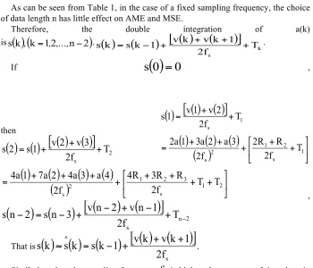
As can be seen from Table 1, in the case of a fixed sampling frequency, the choice of data length n has little effect on AME and MSE.
Therefore, the double integration of a(k) is
s
( ) (
k
,
k
=
1
,
2
,...,
n
!
2
)
.( )
(
)
[
( )
(
)
]
ks T f 2 1 k v k v 1 k s k
s = ! + + + + .
If
s
( )
0
=
0
,then
( )
[
( ) ( )
]
( )
( ) ( )
( )
!
"
#
$
%
&
+
+
+
+
+
=
+
+
=
1 s 2 1 2 s 1 sT
f
2
R
R
2
f
2
3
a
2
a
3
1
a
2
T
f
2
2
v
1
v
1
s
( ) ( )
[
( ) ( )
]
( )
( )
( ) ( )
( )
!
"
#
$
%
&
+
+
+
+
+
+
+
+
=
+
+
+
=
2 1 s 3 2 1 2 s 2 sT
T
f
2
R
R
3
R
4
f
2
4
a
3
a
4
2
a
7
1
a
4
T
f
2
3
v
2
v
1
s
2
s
,(
) (
)
[
(
) (
)
]
n 2s
T
f
2
1
n
v
2
n
v
3
n
s
2
n
s
+
!!
+
!
+
!
=
!
That is
( ) ( ) (
)
[
( ) (
)
]
s
f
2
1
k
v
k
v
1
k
s
k
s
k
s
"
#=
!
+
+
+
.Similarly, when the sampling frequency
f
s is higher, the accuracy of time domain integration will be improved obviously. Data length n has little effect on precision.ensure data transmission, sampling frequency is generally chosen as
f
s=
100
HZ
, which can guarantee the precision of time domain integration.5
Simulation results
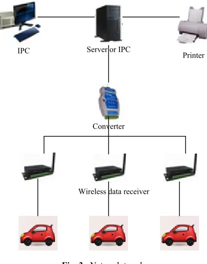
The network topology of this study is shown in Figure 3.
IPC Server or IPC Printer
Converter
Wireless data receiver
Fig. 3. Network topology
1000 2000 3000 4000 5000 -4
-3 -2 -1 0 1 2
A
cc
el
er
at
ion am
pl
itude
Data length (a)
1000 2000 3000 4000
-0.08 -0.06 -0.04 -0.02 0.00 0.02 0.04 0.06
V
el
oc
ity a
m
pl
itude
Data length (b)
1000 2000 3000 4000 -8
-6 -4 -2 0
D
ispl
ac
em
ent
am
pl
itude
Data length (c) x10-3
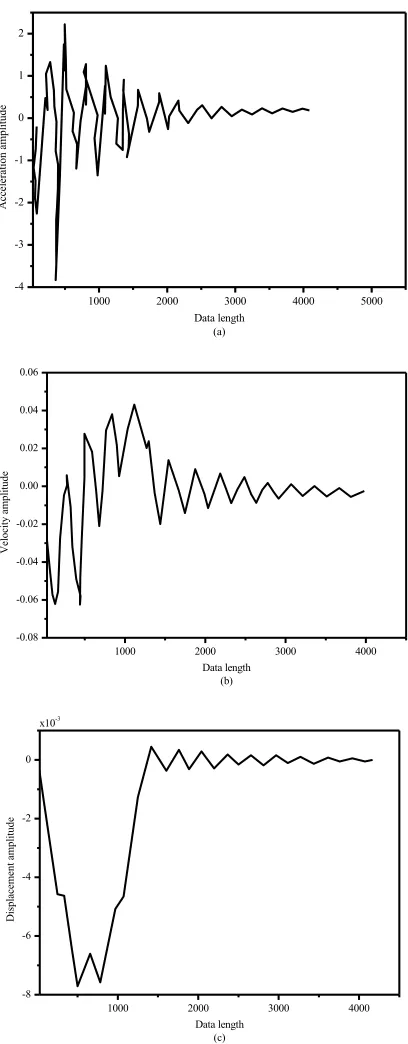
By the above method, we can obtain the speed and displacement signal waveform based acceleration signal, which is shown in Figure 5. There is no trend term for the displacement signal waveform, so the initial value is zero.
1000 2000 3000 4000
-0.08 -0.06 -0.04 -0.02 0.00 0.02 0.04 0.06
A
mp
litu
de
(m/s
)
Data length (a)
1000 2000 3000 4000
-8 -6 -4 -2 0
A
mp
litu
de
(m)
Data length (b) x10-3
6
Conclusions
The vibration signal (acceleration, velocity and displacement signals) is the basis for modal parameters, and it also is the basis of structural modal parameter identifica-tion. Through the displacement signal, we can obtain the operation and health status of structure. In the actual project, displacement sensor has many problems such as low precision, high price, installation difficulty and so on. Therefore, we can use the inte-gral relation between acceleration, velocity, and the displacement signal to obtain the displacement signal. Based on the analysis of the relationship between the trend terms coefficients, this paper proposes a method of fast integration, so as to obtain speed, displacement signal of trend items elimination and get simulation instructions. In the case of further analysis of the fixed sampling frequency fs, we obtain the relationship between the data length n and the precision of the trend item, apply the conclusion to the acceleration signal processing acquired by the wireless sensor network and get corrected acceleration signal, velocity and displacement signal. Therefore, it is a nec-essary basis for follow-up large-scale structural modal identification.
7
References
[1]Assaf, Z. J., Petrov, D. A., & Blundell, J. R. (2015). Obstruction of adaptation in diploids by recessive, strongly deleterious alleles. Proceedings of the National Academy of Scienc-es, 112(20), 2658-66. https://doi.org/10.1073/pnas.1424949112
[2]Burlayenko, V. N., Altenbach, H., & Sadowski, T. (2015). An evaluation of displacement-based finite element models used for free vibration analysis of homogeneous and compo-site plates. Journal of Sound & Vibration, 358, 152-175. https://doi.org/10.1016/j.jsv. 2015.08.010
[3]Elahi, A. S., Ghoranneviss, M., Elahi, A. S., & Ghoranneviss, M. (2014). Discrete coils based measurement of plasma displacement in the ir-t1 tokamak. Journal of Nuclear & Particle Physics, 4(1), 42-46.
[4]Han, F., Zhong, D. W., Mo, J. Y., & Chen, H. (2014). Parameter identification for under-ground powerhouse of pumped-storage power station based on arma time-series model. Applied Mechanics & Materials, 578-579, 1196-1199. https://doi.org/10.4028/www.scient ific.net/AMM.578-579.1196
[5]Hang, X. C., Jiang, L. W., Gu, M. H., Wu, S. Q., & Fei, Q. G. (2015). Accuracy of modal damping identification using frequency domain decomposition method. Zhendong Gong-cheng Xuebao/journal of Vibration Engineering, 28(4), 518-524.
[6]He, X. H., Hua, X. G., Chen, Z. Q., & Huang, F. L. (2011). EMD-based random decrement technique for modal parameter identification of an existing railway bridge. Engineering Structures, 33(4), 1348-1356. https://doi.org/10.1016/j.engstruct.2011.01.012
[7]Kim, C. W., Kawatani, M., & Hao, J. (2012). Modal parameter identification of short span bridges under a moving vehicle by means of multivariate AR model. Structure and Infra-structure Engineering, 8(5), 459-472. https://doi.org/10.1080/15732479.2010.539061
[9]Maekawa, A., Tsuji, T., Takahashi, T., & Noda, M. (2014). A method using optical con-tactless displacement sensors to measure vibration stress of small-bore piping. Journal of Pressure Vessel Technology,136(1), 0112021-1120210.
[10]Meulenbeld, B. (2015). An accurate calculation method of vibration displacement based on vibration acceleration signal. Journal of Information & Computational Science, 12(1), 41-49. https://doi.org/10.12733/jics20104848
[11]Squicciarini, G., Thompson, D. J., & Corradi, R. (2014). The effect of different combina-tions of boundary condicombina-tions on the average radiation efficiency of rectangular plates. Journal of Sound & Vibration, 333(17), 3931-3948. https://doi.org/10.1016/ j.jsv.2014.04.022
[12]Su, W. C., Liu, C. Y., & Huang, C. S. (2014). Identification of Instantaneous Modal Pa-rameter of TimeVarying Systems via a WaveletBased Approach and Its Application.
Computer Aided Civil and Infrastructure Engineering, 29(4), 279-298.
https://doi.org/10.1111/mice.12037
[13]Wang, S., Huang, W., & Zhu, Z. K. (2011). Transient modeling and parameter identifica-tion based on wavelet and correlaidentifica-tion filtering for rotating machine fault diagnosis. Me-chanical systems and signal processing, 25(4), 1299-1320. https://doi.org/10.1016/ j.ymssp.2010.10.013
[14]Yan, W. J., & Ren, W. X. (2012). Operational modal parameter identification from power spectrum density transmissibility. ComputerAided Civil and Infrastructure Engineering,
27(3), 202-217. https://doi.org/10.1111/j.1467-8667.2011.00735.x
[15]Zhang, J., Ouyang, H., Zhang, Y., & Ye, J. (2015). Partial quadratic eigenvalue assignment in vibrating systems using acceleration and velocity feedback. Inverse Problems in Science and Engineering, 23(3), 479-497. https://doi.org/10.1080/17415977.2014.922076
8
Authors
Lian XUE is Professor at WuHan Technology And Business University, Wuhan 430065, China ([email protected]).
Cheng-song HU is Professor at WuHan Technology And Business University, Wuhan 430065, China ([email protected]).