Available Online at www.ijpret.com 43
INTERNATIONAL JOURNAL OF PURE AND
APPLIED RESEARCH IN ENGINEERING AND
TECHNOLOGY
A PATH FOR HORIZING YOUR INNOVATIVE WORK
DESIGN OF A DEVICE FOR OPTICAL COMMUNICATION
SONIYA S BHAGAT1, SONIA KUWELKAR2, MR. JAN GUNKE31.Master of Engineering, Microelectronics ETC Dept., Goa College of Engineering, Goa University, Ponda, India. 2.Asst. Professor, ETC Dept., Goa College of Engineering, Goa University, Ponda, India.
3.Head of Architecture & Innovation Dept. R&D Siemens Ltd, Verna, India.
Accepted Date: 05/03/2015; Published Date: 01/05/2015
\
Abstract: Optical communication uses light to carry information. It does not conduct electricity. This prevents problems with ground loops and conduction of lightning. Optical fiber communication is unaffected by neighboring electromagnetic radiation compared to electrical communication. The optical fiber is electrically non-conductive, so it does not act as an antenna to pick up electromagnetic signals. Purpose of this project is to design an optical device between both the equipment’s and transmission and reception of signals is done using optical communication. Signals from different protocols will be multiplexed before transmission and demultiplexed after reception of signals through optical fiber.
Keywords: Optical fibre, optical communication, protocols, multiplex, demultiplex.
Corresponding Author: MS. SONIYA S BHAGAT
Access Online On:
www.ijpret.com
How to Cite This Article:
Soniya S Bhagat, IJPRET, 2015; Volume 3 (9): 43-48
Available Online at www.ijpret.com 44 INTRODUCTION
In fibre-optic communication, information is transmitted from one place to another by sending pulses of light through an optical fibre. Optical fibre is generally chosen for systems requiring higher bandwidth or spanning longer distances than electrical cabling can accommodate [2]. Optical fibres have largely replaced copper wire communications in core networks in the developed world. Its high bandwidth capabilities and low attenuation characteristics make it ideal for gigabit transmission and beyond [1]. It can function as a waveguide to transmit light between the two ends of the fibre. Fibres are used instead of metal wires because signals travel along them with less loss and are also immune to electromagnetic interference.
Main aim of this paper is to develop a device which will transmit the signals between both the equipment’s in the laboratory by using more than one protocol namely RS232 and Ethernet. Application of this device will reduce the external interference to minimum compared to electrical interface, so that signals transmitted and received between the equipment’s will be immune to other interference. This paper focuses on the design of the device and how it functions. It also includes results of verification done at different stages in the design using two protocols.
DESIGN OF DEVICE
A. Overview Of Design
Optical interface device is a transceiver which consists of transmitter and receiver section. The transceiver consists of Serializer, Deserializer, interfacing ICs (Integrated Circuits), voltage regulators, and SFP module. Information is transmitted and received between both the equipment’s.
B. Design Details
Available Online at www.ijpret.com 45
Output from MAX232 is transmitted via RS232 cable to the destination. Similarly output from MIDCOM IC is transmitted via Ethernet cable to the destination.
C. Transmitter section
Transmitter section of the device consists of source, DS90C241. Interfacing ICs namely MAX232, MIDCOM IC, are common components for both transmitter and receiver.
DS90C241: This is the serializer which is located at the transmitter end. It will accept the inputs from the interfacing ICs and multiplex the signals and then will transmit the output to SFP module. The DS90C241 Chipset translates a 24-bit parallel bus into a fully transparent data/control LVDS serial stream with embedded clock information. This single serial stream simplifies transferring a 24-bit bus over PCB traces and cable by eliminating the skew problems between parallel data and clock paths. It features 5 MHz-35 MHz clock embedded and DC-Balancing 24:1. It is 48-pin TQFP package. [3]
MAX232: This is the interfacing IC between Serializer and RS232 connector. It is the member of family of line drivers which is used for EIA/TIA-232E and V.24/V.28 communication interfaces. Output obtained is within the range of -0.3V to (VCC +0.3V). Supply voltage required by this IC is within the range of -0.3V to 6V. Its applications are Portable Computers, Low-Power Modems, Interface Translation, Battery-Powered RS-232 Systems, Multidrop RS-232 Networks. [7]
10/100Mbps SMD Transformer: It is the transformer used to accept the input from Ethernet. It meets IEEE 802.3 standard, Supports most 10/100Mbps PHYs requiring 1:1 Turn Ratios. It is Low-profile package. It has high isolation voltage. It has ISO 9002 Certified manufacturing facilities. Operating temperature range is from -40 to+85C. [9]
KSZ8001: It will accept the output from 10/100Mbps SMD Transformer as input and provide single ended output. The KSZ8001 is a 10BASE-T/100BASE-TX/100BASE-FX Physical Layer Transceiver, operating the core at 1.8 volts to meet low voltage and low power requirements. The solution provides interfaces to transmit and receive data. It is 1.8V CMOS design, power consumption 250 mW. It is 48 Pin LQFP, 48 Pin SSOP. [10]
Available Online at www.ijpret.com 46
D. Receiver section
Receiver section consists of destination, DS90C124. SFP module, voltage regulators are common components for both transmitter and receiver. Two voltage regulators are used namely LP 3997-3.3V regulator and TPS77601 which is 5V regulator.
DS90C124: The DS90C124 is 48 pin chipset. The DS90C124 receives the LVDS serial data stream and converts it back into a 24-bit wide parallel data and recovered clock. The Deserializer can attain lock to a data stream without the use of a separate reference clock source; greatly simplifying system complexity and overall cost. The Deserializer extracts the clock/control information from the incoming data stream and deserializes the data. The Deserializer monitors the incoming clock information to determine lock status and will indicate lock by asserting the LOCK output high. [3]
SFP module: The Small Form Factor Pluggable (SFP) module accepts electrical input and converts it into optical signal. This signal is then transmitted through optical cable and SFP module at the other end will convert optical signal into electrical signal. Module consists of PECL. Positive emitter-coupled logic (PECL) is a further development of ECL using a positive 5V supply instead of a negative 5.2V supply. Electrical signal from serializer is connected to PECL. Output from PECL is provided as input to laser driver. At the output of laser driver, a laser is connected. Electrical signal is converted to optical signal. This optical signal is then transmitted to the receiver. At the receiving end photodiode is present. Conversion from optical to electrical signal takes place over here. Output from this is connected to pre amplifier. Its output is then fed to post amplifier. Output of post amplifier is the connected as input to Deserializer. [8]
LP3997: The LP3997 regulator is designed to meet the requirements of portable, battery-powered systems, providing accurate output voltage, low noise, and low quiescent current. The LP3997 provides 3.3V output at up to 250mA load current. The chip architecture is capable of providing output voltages as low as 0.8V.When switched in shutdown mode; the power consumption is virtually zero. It is 8-Lead VSSOP Package. Its applications are Portable Consumer Electronics, Cellular Handsets, Laptop and Palm Computers. [5]
Available Online at www.ijpret.com 47
OPTICAL CABLE
One device is placed near the source and other device is located near destination. When the source transmits data, transmitter near the source end will transmit the data to the receiver located near destination through optical cable. When destination responds to the data, the transmitter near destination will transmit the data to the receiver near source. Optical cable will be of maximum 5 meters.
COMPARISON
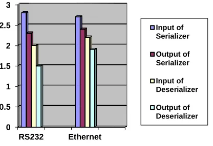
The comparison between two interfacing ICs i.e. MAX232 and MIDCOM IC for RS232 and Ethernet is provided in graphical form. It is observed that signal levels through RS232 and Ethernet differs at the input and output of deserialiser, output of serialiser and input of interfacing ICs. Between the output of serialiser and input of deserialiser, conversion of electrical signal to optical and then conversion back to electrical signal was done using SFP module.
Fig 1. Comparison of signals
CONCLUSION
An optical interface between equipment’s which is designed for transmission and reception of signals using above components were verified. At each stage, voltage levels via RS232 and Ethernet were checked which means correct transmission of signal was obtained. This device can be used to test equipment in the laboratory. Use of optical interface will result in less attenuation of signal and more immune to noise.
0 0.5 1 1.5 2 2.5 3
RS232 Ethernet
Input of Serializer
Output of Serializer
Input of Deserializer
Available Online at www.ijpret.com 48 REFERENCES
1. Prachi Sharma, Suraj Pardeshi, Rohit Kumar Arora, Mandeep Singh; “A Review of the Development in the Field of Fiber Optic Communication Systems International Journal of Emerging Technology and Advanced Engineering; Volume 3, Issue 5, May 2013.
2. Arun Gangwar, Bhawana Sharma; "Optical Fiber: The New Era of High Speed Communication (Technology, Advantages and Future Aspects)"; International Journal of Engineering Research and Development; Volume 4, Issue 2 (October 2012).
3. DS90C241/DS90C124,5-35MHz DC-Balanced 24-Bit LVDS Serializer and Deserializer, Data Sheet.
4. TS775xx with reset output,TPS776xx with PG output fast-transient-response 500mA Low Drop Voltage Regulator Data Sheet .
5. Micro power 250-mA CMOS LDO Regulator With Error Flag and Power-On-Reset, Data Sheet.
6. CRYSTAL OSCILLATOR (XO) 100 kHZ TO 250 MHZ,Si510/511, DataSheet.
7. 5V-Powered, Multichannel RS-232 Drivers/Receivers, Data Sheet.
8. SFP Transceiver Series (TRFxxxx), Technical Data for SFP Transceiver Series (Rev. 2.1/June 17th, 2004).
9. 10/100Mbps SMD Transformer, Data Sheet.