Available Online at www.ijpret.com 1
INTERNATIONAL JOURNAL OF PURE AND
APPLIED RESEARCH IN ENGINEERING AND
TECHNOLOGY
A PATH FOR HORIZING YOUR INNOVATIVE WORK
APPLICATION OF UPFC FOR DAMPING POWER SYSTEM OSCILLATIONS
NISHIGANDHA M. INGALE, ASST. PROF .P. JAGTAPDepartment of Electrical Engineering G. H. Raisoni College of Engineering Nagpur, India Accepted Date: 15/03/2016; Published Date: 01/05/2016
\
Abstract: Utilization of power increases so the demand of electrical power has increases. The system becomes more complicated day by day to operated and control. System is less protected for increasing load and disturbances. It may result in to insufficient control with power transfer in the system to full fill power demand. Therefore power cannot transfer up to its full strength of transmission line.
Keywords: UPFC model, stability, PSS.
Corresponding Author: MS. NISHIGANDHA M. INGALE
Access Online On:
www.ijpret.com
How to Cite This Article:
Nishigandha M. Ingale, IJPRET, 2016; Volume 4 (9): 1-9
Research Article Impact Factor: 4.226 ISSN: 2319-507X Nishigandha M. Ingale, IJPRET, 2016; Volume 4 (9): 1-9 IJPRET
Available Online at www.ijpret.com 2 INTRODUCTION
The continuous increasing power demand required to increases the generation of power to fulfill the demand, the need of flexible transmission system arises. FACTS is basically flexible ac transmission system .As the name suggest it is flexible for sending power as required by users. FACTS devices were used for improving the steady state stability and dynamic stability [1-3] Unified power flow controller (UPFC) is the most flexible device and can control active and reactive power flow in transmission system. Fault may result in loss of synchronism. If the fault cannot clear within a small duration of time. Loss of synchronism results in interruption of power supply. Also the oscillations produce in the system. Operation and power control in a disturb system is difficult.
So, in this work, UPFC is effectively used to damp out oscillations in power system [5] as it has a property of combine series and shunt controllers. The main function of UPFC is to control power flow with the help of controlling the parameters. UPFC is also able to damp oscillations in power system and improve stability in the system [4].Thus it is the best FACTS device among all and very popular today.
BASIC CONFIGURATION OF THE UPFC
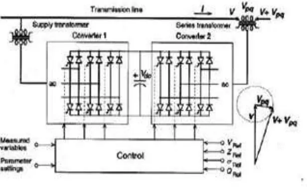
The basic configuration of the UPFC having two voltage source inverters (VSI), one converter is connected in shunt with the transmission line while the other is connected in series with the transmission line Figure 1 shows the schematic diagram of UPFC. The UPFC is a series shunt FACTS device having two branches, the series and shunt branch. Each of the branches consists of power electronic based converter and a transformer. The series branch having a voltage source converters (series converter) or SSSC which insert voltage in the line via series mode through transformer. The inserted voltage is of controllable magnitude and phase angle, while shunt converter or Static Synchronous Compensator (STATCOM) is used to maintain the voltage of the bus constant where it is connected. These two converters are joined via a common dc capacitor.
Available Online at www.ijpret.com 3 Figure 1: Implementation of the UPFC by two back-to-back voltage sourced convertor
UPFC is capable of both supplying to and absorbing from the power system through the excitation converter and transformer a controllable amount of reactive power and inserting a voltage of controllable magnitude and phase angle in series with the transmission system through the converter and transformer
POWER SYSTEM STABLIZER
Rotor oscillations is one of the main cause for oscillations in the system. Solution for oscillation problem is to introduce PSS within the plant in the system. Power System Stabilizer (PSS) is a feedback controller. It is installed in the Automatic Voltage Regulator of the Generator. Main function of PSS is to damp generator rotor oscillations and improve system stability. The PSS give a signal to excitation system in order to damp the oscillations.
STRUCTURE OF PSS
Research Article Impact Factor: 4.226 ISSN: 2319-507X Nishigandha M. Ingale, IJPRET, 2016; Volume 4 (9): 1-9 IJPRET
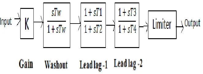
Available Online at www.ijpret.com 4 Figure 2: Structure of PSS
Washout block: Washout filter is basically a high pass filter that prevents frequent operation
the PSS for slow change in operating point occur. This filter set the frequency range from which range to up to which range the PSS begins to operate. Time constant Tw is called wash out time constant to pass the signals related with the rotor speed oscillations to pass without change. Lower value of Tw is taken to damp out local mode oscillations and higher values of Tw are used for damping out inter area oscillations.
Dynamic compensator: It with two lead lag block having transfer function
Where Ks is the gain of PSDC where time constant T1, T2, T3, T4 are selected so that to compensate the phase lag between the excitation system input and generator torque.
Limiter: During the Disturbances introduce in the system, limiter and filter are the most
effective device against those disturbances .It pass the swing mode frequency signal to balance the system oscillations. Proper tuning of PSS is important for damping rotor oscillations .It cancel the negative oscillations.
CASE STUDY
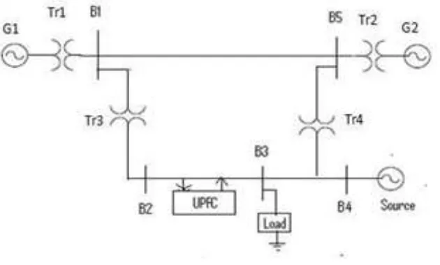
Available Online at www.ijpret.com 5 Figure 3: Structure of 2-machines 5-bus system
In a 500 kV /230 kV transmission network which is connected in a loop configuration .It is two machine five bus system .Transformer Tr3 is connected in between B1 and B2. Transformer Tr4 is connected in between B5 and B4. UPFC is connected in between B2 and B3. Load of 200 MW is connected at bus B3.This form a close loop system. Transformer primary and secondary are connected in such a way that they can eliminate the harmonics.
Following cases are consider:
Case 1: Multi machine system without UPFC without fault.
This system is healthy system without any fault created in it. This is the stable system.
Case 2: Multi machine system without UPFC with three phase fault.
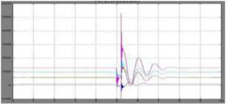
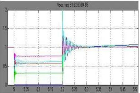
In this model UPFC is not connected in the system and three phase fault is created near bus 1 for duration of 5 to 5.2 sec. Oscillations are observed in voltage at different buses and oscillations in power (MW). System is unstable. Oscillations are undamped.
Case 3: Multimachine system with UPFC with fault.
In this model UPFC is connected in between bus B2 and B3. Three phase fault is created simultaneously near bus B1.Oscillations are observed in voltages and power at different buses. UPFC can damped out these oscillations time required for damping will be minimize.
Research Article Impact Factor: 4.226 ISSN: 2319-507X Nishigandha M. Ingale, IJPRET, 2016; Volume 4 (9): 1-9 IJPRET
Available Online at www.ijpret.com 6
A. System without fault without UPFC
Consider two machine five bus systems without creating any fault the scope will show the results without oscillations. The active, reactive power and voltages in p.u at different buses will be obtained. Results are straight line without any oscillations
Figure 4: Active power, reactive power and bus voltages at different buses without fault
B. Three phase fault (without UPFC)
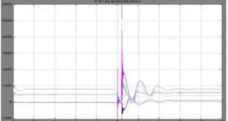
In two machine five bus system and fault is created near bus B1. A result obtained in the scope is shown which shows system is unstable with oscillations in power and voltage.
Available Online at www.ijpret.com 7 Figure 6: Voltage in p.u. at different buses without UPFC
Figure 7: Reactive power in MW at different buses without UPFC
C. Three phase fault (with UPFC)
In two machine five bus system and fault is created near bus B1 and UPFC is connected. Results obtained in the scope which shows system oscillations are damped in power and voltage
Research Article Impact Factor: 4.226 ISSN: 2319-507X Nishigandha M. Ingale, IJPRET, 2016; Volume 4 (9): 1-9 IJPRET
Available Online at www.ijpret.com 8 Figure 9: Reactive power in MW at different buses with UPFC
Figure 10: Voltage in p.u at different buses with UPFC
CONCLUSION
This paper mainly focus on damping of oscillations using UPFC and increase in stability of the power system. The UPFC performance on the system network under three phase fault are studied.
Effectiveness of UPFC is observe .Simulation results also shows the effectiveness of UPFC. Oscillation in real and reactive power and load bus voltages are damp. Time required for damping power system oscillations is much reduce if we use UPFC and system will get stable in small duration of time.
REFERENCES
Available Online at www.ijpret.com 9
2. M. Noroozian, L. Angquist, M. Ghandhari and G. Andersson, “Use of UPFC for optimal power control”, IEEE Trans. on Power Delivery vol. 12, No. 4, pp. 1629-1634, 1997.
3. M. Ghandhahi, G.Adersson, I.A.Hiskens, “Control Lyapunov functions for series devices”, IEEE Transactions on Power Delivery, vol. 16, No.4,pp 689-694, 2005
4. Guo, M. L. Crow, and Jagannathan Sarangapani, “An Improved UPFC Control for Oscillation Damping”, IEEE Transactions on Power Systems, vol. 24, No. 1, 2009.
5. Mr. R. H. Adware, Prof. P. P. Jagtap and Dr. J.B. Helonde, “power system oscillations Damping using UPFC damping controller” Third International Conference on Emerging Trends in Engineering and Technology, 340-344.
6. N.G.Hingorani, L.Gyugi, Understanding FACTS. IEEE Press, 2000.
7. K. Ogata, Modern Control Engineering, Fourth Edition, Prince Hall, 2002, Chapter, 10.
8. Meysam Eghtedari, Reza Hemmati, and Sayed Mojtaba Shirvani Boroujeni,” Multi objective control of UPFC using PID type Controllers” International Journal of the Physical Sciences Vol. 6(10), pp. 2363-2371, 18 May, 2011.