Management and Research
Available online at: www.ijstmr.comIJSTMR
©
2016 | All Rights Reserved 65An Add on Self Tuning Control System Using
PR Controller for UPFC Application
Ankita singh PG,Student
Electrical Engineering Department, Matoshri College of Engineering.Odha,
Nashik, MH, India
Prof. S. S. Khule Assistant Professor and HOD Electrical Engineering Department Matoshri College of Engineering.Odha
Nashik, MH, India
Abstract: The growing energy demand has caused the interconnected power systems to operate close to their stability
limit. As a consequence, poorly damped low-frequency oscillations are becoming a common phenomenon. Such oscillations weaken the system security and if not effectively damped can lead to widespread blackouts. A relatively recent solution based on the advancements in high-power semiconductors is the Flexible AC Transmission System (FACTS) technology meant for transmission locations. FACTS technology comprises of a multitude of FACTS devices among which the Unified Power Flow Controller (UPFC) possesses a unique capability of providing both power flow and voltage control particularly, with a suitable transient control system the UPFC can satisfactorily mitigate power system oscillations. This thesis proposes an adaptive control scheme that supplements an existing Proportional Resonant (PR) UPFC control system in damping power system oscillations. PI controller can also be used but it has more steady state error than PR controller. However, its application in a power system that experiences continuously changing system conditions demands its frequent re-tuning. On the other hand, the proposed scheme in this project is a Self Tuning (ST) controller that automatically adapts to the system changes and thereby provides an optimal control for a wide range of operating scenarios. By using ST Controller the problem of retuning is get solved. The simulation results based on MATLAB/ SIMULINK were performed to verify the effectiveness of PR controller of UPFC.
Keywords: Flexible AC Transmission System, Unified Power Flow Controller, self-tuning, proportional integral, proportional resonant.
________________________________________________________________________________________________
I. INTRODUCTION
In recent years energy, environment, right-of-way, and cost issues have delayed the
development of each generation facilities and new transmission lines, while the demand for electrical power
has continued to grow. This situation has necessitated a review of the standard facility ideas and practices to
attain larger operative flexibility and higher utilization of existing power systems. During the last two decades, if not
revolution semiconductor, advances have been made in high management technology. These technologies have been
instrumental within the broad application of HVDC transmission and facility intertie schemes, and they have already
made a big impact on AC transmission via the increasing use of thyristor controlled static volt-ampere compensators
(SVCs).
A Unified Power Flow Controller (or UPFC) is an electrical device for providing fast-acting reactive power
compensation on high-voltage electricity transmission networks. It uses a pair of three-phase governable bridges
to manufacture current that's injected into a cable employing a series electrical device. The controller can control active
and reactive power flows in a cable. The UPFC uses solid state devices, which give purposeful flexibility, generally
not possible by typical thyristor controlled systems.
The UPFC is a combination of a static synchronous compensator (STATCOM) and a static synchronous series
IJSTMR
©
2016 | All Rights Reserved 66 and reactive power flows within the cable. If there are any disturbances or faults in the supply aspect, the UPFC will notwork. The UPFC operates only below balanced sin wave supply. The controllable parameters of the UPFC area
unit electrical phenomenon in the line are impedance, phase angle and voltage.
The UPFC allows a secondary however vital perform such as stability management to suppress power
grid oscillations up the transient stability of power grid [1]. The UPFC can give synchronous management of all basic
power system parameters (transmission voltage, impedance and part angle). The controller can fulfill functions of
reactive shunt compensation, series compensation and phase shifting meeting multiple management objectives. From a
functional perspective, the objectives are met by applying a boosting electrical device injected voltage and an
exciting electrical device reactive current. The injected voltage is inserted by a series transformer.
Unified power flow controller (UPFC) has been the most versatile Flexible AC gear mechanism (FACTS)
device because of its ability to regulate real and reactive power on transmission lines whereas dominant the voltage of the
bus to that it's connected. UPFC being a multi-variable grid controller it's necessary to investigate its effect on power
system operation. In recent years, greater demands have been placed on the transmission network, and these demands
will continue to increase thanks to the increasing variety of nonutility generators and heightened competition among
utilities themselves. Increasing demand on transmission, absence of long term planning and the ought to give open access
to generating corporations and customers all at once have created tendencies toward less security and reduced quality
of offer. This controller offers substantial advantages for the static and dynamic operation of power system. The UPFC is
the most versatile and sophisticated power equipment that has emerged for the control and optimization of power flow
in wattage transmission systems.
II. LITURATURE SURVEY
In this paper “An Add-On Self-Tuning system for a UPFC Application” paper an add-on self-tuning (ST)
management theme for a Unified Power Flow Controller (UPFC) to help its conventional PI management system in
damping power oscillations is represented. For a wide range of operational conditions, the conventional PI-UPFC unless
retuned suffers from scant non optimal damping performance. To overcome this drawback, the authors propose
supplementing the PI controllers with an ST feedback loop comprised of a symbol and a postscript control rule [1].
The most purpose of the paper ”Optimum Tuning of Unified Power Flow Controller via Ant Colony
Optimization Technique” is to spot the optimum location of the Unified Power Flow Controller UPFC
in wattage systems. In this paper, the CPF technique is used within the proposed algorithmic rule to spot the candidate
buses for the UPFC placement [2].
In this paper “facility Security Improvement Using the Unified Power Flow Controller
(UPFC)”a rule to notice the operative purpose of UPFCs for the improvement of system security level is presented. The
sensitivity indicating the change of the index due to the changes within the UPFC real power output is calculated. In each
iteration, according to this sensitivity, the proposed rule finds a new UPFC operative purpose to scale back the index or
increase the safety margin. The projected rule enhances the security level of power system [3].
In this paper “Application of UPFC to Increase transient stability of Inter-Area Power System.” the
improvement of transient stability of inter-area power system is presented. The mathematical model of UPFC is present
in this paper. UPFC can be modeled as fictitious active and reactive load of power system. To incorporate UPFC into
power system, the fictitious load models are transferred to susceptance models. These models can be controlled by
parameters on a UPFC .This paper uses the line power flow between area 1 and area 2 to control a UPFC [10].
This paper “ Load flow studies with upfc power injection model” focused on to improve the bus voltage and to
IJSTMR
©
2016 | All Rights Reserved 67 Newton-Raphson (NR) power flow algorithm. The steady state model of the UPFC, derived from two voltage sourcerepresentation, is presented and analyzed in detail [11].
In this paper “the unified power flow controller. a new approach to power transmission control” there is a
description of the basic concepts of the proposed generalized P and Q controller and compares it to the more
conventional, but related power flow controller such as the Controlled Series Capacitor and Thyristor Controlled Phase
Angle Regulator. The paper also presents results of computer simulations showing the performance of the UPFC under
different system conditions, providing the necessary functional flexibility required to solve many of the problems facing
the utility industry [12].
In “Application of UPFC-based Adaptive Controller for Damping Inter-Area Oscillations “ paper a UPFC-based
non-linear adaptive controller is proposed and designed to damp the tie line power oscillations. The adaptive controller
design is based on determination of control signal using a new linear quadratic pole placement control law and
identification of power system parameters using recursive least squares method with variable forgetting factor. This
paper also describes the recently introduced proportional resonant (PR) and their quality for grid-connected converters
current control [15].
III. SYSTEM OVERVIEW
Unified power flow controller
The Unified Power Flow Controller is consists of two switching converters, that are considered as voltage sourced
inverters using gate thyristor valves. These inverters "VSC1” and "VSC2" are operated with a common dc link provided
by a dc storage capacitor. With this arrangement the ac power converter in which the active power can freely flow in
either direction between the ac terminals of the two inverters and each inverter can severally produce as well as absorb
the reactive power at its own ac output terminal. Since the series converter of the UPFC will inject a voltage with
variable magnitude and phase angle it can exchange active power with the transmission line with the help of series
transformer. However a UPFC as a whole (both converter) cannot supply or absorb active power in steady state (except
for the power drawn to compensate for the losses).Until it has a power source at dc terminals. Therefore the shunt branch
is needed for compensate (from the system for any real power drawn/supplied by the series branch and the losses. When
the power balance is not maintained, at that time the capacitor cannot remain at a constant voltage. Shunt branch also can
independently exchange reactive power with the system. Inverter 2 provides the main function of the UPFC by injecting
a voltage Vpq with controllable magnitude Vpq (0≤ Vpq≤ Vpqmax) and phase angle ρ (0≤ρ ≤ 360°), at the power
frequency, insert with line by an insertion transformer. This injected voltage considered as synchronous ac voltage
source.
The function of converter1 is to provide or absorb the active power required by converter 2 at the common dc link.
The power of the dc link is converted back to ac and coupled to the transmission line by a shunt-connected transformer.
If reactive power is needed then inverter 1 can also produce or absorb controllable reactive power, so it can provide
independent shunt reactive compensation for the line. It is also important to note that whereas there is a closed "direct"
path for the active power negotiated by the action of series voltage injection through Inverters 1 and 2 back to the line,
corresponding the reactive power exchanged is supplied or absorbed locally by Inverter 2 and therefore the reactive
power cannot flow through the line. So the Inverter 1 can be operated at a unity power factor or be controlled to have a
reactive power exchange with the line independently of the reactive power exchanged by Inverter 2. That means there is
no continuous reactive power flow. Inverter-1 is connected to the power system through a transformer T1 in shunt and
IJSTMR
©
2016 | All Rights Reserved 68 with the transmission line. The transformers T1 and T2 can be referred to as shunt and series transformers respectivelyfor the purpose of clarity.
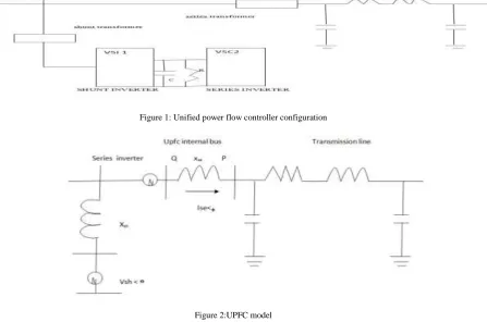
Where the shunt inverter and series inverter of a UPFC are modeled as a voltage source series with their
transformer reactance is the simplest of al1 the models. The model provides for detailed interaction between the series
and the shunt inverter. Figure shows the UPFC model. Xsh and Xse represent the reactance of transformers T1 and T2
respectively. Vsh and Vse, represent the voltage generated by the shunt and the series inverter respectively. Bus-E and
bus-F represent the UPFC bus and the transmission line side bus of UPFC respectively.
Figure 1: Unified power flow controller configuration
Figure 2:UPFC model
For performing load flow studies with UPFC, the series and the shunt inverters are assumed to produce balanced 50 Hz voltages of variable magnitude and phase angle. The shunt and the series voltage sources phasors can be mathematically represented as
^ ^
(cos
sin
)
(cos
sin
)
sh sh sh sh
se sem se se
V
V
j
V
V
j
Where Vsh and Vse, are the root mean squared magnitudes of the shunt and the series voltage sources.
UPFC CONTROLL SYSTEM
The unified power flow controller (UPFC) is one of the most commonly used FACTs controllers and its main function is
to control the voltage, phase angle and impedance of the power system thereby modulating the line reactance and
controlling the power flow in the transmission line. The main components of the UPFC are two voltage source inverters
(VSIs) connected by a common dc storage capacitor which is connected to the power system by a coupling transformers.
One (VSIs) is connected in shunt to the transmission system through a shunt transformer, while the another (VSIs) is
connected in series to the transmission line by a series transformer. Three phase system voltage of controllable
IJSTMR
©
2016 | All Rights Reserved 69 transmission line. So, this inverter will exchange active and reactive power within the line. The shunt inverter is operatedin such a way as to demand this dc terminal power (positive or negative) from the line keeping the voltage across the
storage capacitor (Vdc) constant.
There are many possibilities of operating configurations by combing two or more converter blocks with
flexibility. Among them, there is a novel operating configuration, namely the Generalized Unified Power Flow Controller
(GUPFC) which is significantly extended to control power flows of multiline or a sub-network rather than control power
flow of single line by a Unified Power Flow Controller (UPFC) or Static Synchronous Series Compensator (SSSC). The
UPFC consists of two branches. The series branch consists of a voltage source converter which injects a voltage in series
by a transformer. Since the series branch of the UPFC can inject a voltage with variable magnitude and phase angle it can
exchange active power with the transmission line. The energy storing capacity of this dc capacitor is generally small.
Therefore, real power drawn by the shunt converter should be equal to the real power produced by the series converter.
The reactive power in the shunt or series converter can be chosen independently, giving greater flexibility to the power
flow control. The coupling transformer is used to connect the device to the system.
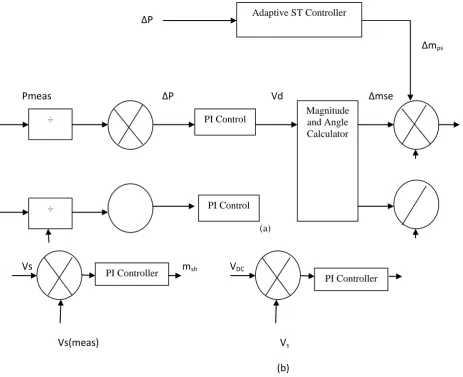
ΔP
Δm
psPmeas
ΔP
Vd
Δmse
(a)
Vs
m
shV
DCVs(meas) V
s(b)
Figure 3: Overall UPFC control system for a damping application. (a) Series VSC control system; (b) Shunt VSC control system.
PR controller-:
Gain at a certain frequency (resonant frequency) is provided by PR controller and normally no gain exists at another
frequency. The transfer functions of single and three phase PR controllers and filters can be derived using internal model PI Controller
PI Controller Magnitude
and Angle Calculator PI Control
PI Control ÷
÷
IJSTMR
©
2016 | All Rights Reserved 70 control, modified state transformation or frequency-domain. PI controller has more steady state error than PR controller.PR controller is also able to identify and eliminate harmonic, which is not possible with PI controller .Using the PR
controllers, the converter reference tracking performance can be enhanced and previously know drawbacks associated
with conventional PI controllers can be alleviated.
Proportional Integral (PI) Controller-:
Now days, the PI controller is most commonly used in industrial application due to its simple structure, easy to
design and low cost. Despite these advantages, the PI controller fails when the controlled object is extremely nonlinear
and uncertain. PI controller will remove forced oscillations and steady state error resulting in operation of on-off
controller and P controller respectively. However, introducing integral mode has a negative effect on speed of the
response and overall stability of the system. Thus, PI controller can not increase the speed of response. It can be expected
since PI controller cannot have means to predict what will happen with the error in near future. This problem can be
resolved by introducing derivative mode which has ability to predict what will happen with the error in near future and
thus to decrease a reaction time of the controller. PI controllers are very often used in industry, especially when speed of
the response is not an issue.
Figure 4. Block diagram PI controller
Block diagram PI controller an integral error compensation scheme, the output response depends in some manner upon the integral of the actuating signal.
IV. SYSTEM’S SIMULATION AND RESULTS
In this phase system of 25 kv, 100MVA is used. One 3 phase Pi section feeder of 21km and another feeder of 2 km
is used. Then one RC system is used for storing the active power in the system. We have also used 2 coupling
transformer, one is shunt coupling transformer which will take or inject voltage from or to shunt converter or
transmission line. Another transformer is series coupling transformer which connects series converter to transmission line
and exchange of power between series converter and transmission line is done by series transformer.
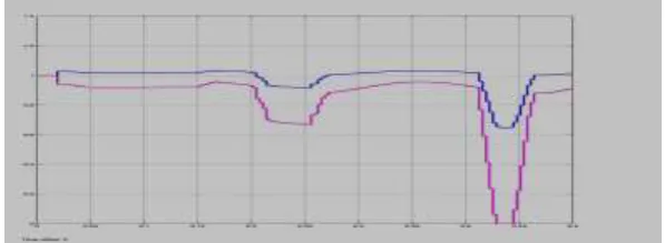
IJSTMR
©
2016 | All Rights Reserved 71 Figure 6: Active and reactive power of series transformer of UPFCThe above 2 figure (fig 5 and 6) graphs shows the voltage, active and reactive power waveform of series transformer of Unified power flow controller. As there is a 3 phase fault between 0.4 to 0.45s and single line to ground fault between 0.2 to 0.25sec, there is a distortion and drop in wave at that time.
Figure 7: Voltage of shunt transformer of UPFC
Figure 8: Active and reactive power of shunt transformer of UPFC
The above 2 figure (fig 7 and 8) graphs shows the voltage, active and reactive power waveform of shunt transformer of Unified power flow controller. As there is a 3 phase fault between 0.4 to 0.45s and single line to ground fault between 0.2 to 0.25sec, so there is a distroation and drop in wave at that time.
Figure 9: Three phase current near shunt transformer of UPFC
The above graph shows the 3 phase current waveform of shunt transformer of UPFC. As there is a fault between 0.4 to
0.45s and single line to ground fault between 0.2 to 0.25sec , so there is a distortion and drop in wave at that time. We
IJSTMR
©
2016 | All Rights Reserved 72 CONCLUSIONThe Unified Power Flow Controller (UPFC), with its unique combination of fast shunt and series compensation, is
a powerful device which can provide power regulation, i.e. voltage magnitude and phase control. The add-on self tuning
with PR controller provided significant damping improvement for the inter-area mode as compared to the conventional
PI-UPFC controllers. The use of constrained-RLS over the standard RLS identifier for online parameter identification
ensured favorable control performance even during large disturbances. UPFC can be used to improve transient stability
margin or to damp low frequency oscillations. The UPFC is the versatile and sophisticated power equipment that has
emerged for the control and optimization of power flow in transmission systems. It offers major potential advantages for
the static and dynamic operation of transmission lines.
REFERENCES
1. An Add-On Self-Tuning system for a UPFC Application”,” in Proc. IEEE Power Eng. Soc. Gen. Meet., 2007, pp. 1–6.
2. Z.Hamid, I. Musirin Member IEEE, M.M.Othman, M.R.Khalil Faculty of Electrical Engineering, Mara University of Technology, Selangor, Malaysia “Optimum Tuning of Unified Power Flow Controller via Ant Colony Optimization Technique”.
3. Bruno, Student Member, IEEE, and Massimo La Scala, Senior Member “Unified Power Flow Controllers for Security-Constrained Transmission Management Sergio”, IEEE June 2010.
4. A. Ajami1, PHD Student, S.H. Hosseini2, Member IEEE.”line current balancing exploitation unified power flow controller”
5. Sajjad Golshannavaz, Farrokh Aminifar, Member, IEEE, and Daryoush Nazarpour “Application of UPFC to Enhancing Oscillatory Response of Series-Compensated Wind Farm Integrations” IEEE transactions on smart grid, vol. 5, no. 4, july 2014
6. G. M. Huang and Y. Li, “Impact of Thyristor Controlled Series Capacitor on Bulk Power System Reliability,” in proc. IEEE Power Engineering Society Summer Meeting, Chicago, America, Jul. 2002,pp. 975-980.
7. H. I. Shaheen, Student Member, IEEE, G. I. Rashed, Student Member, IEEE, and S. J. Cheng, Senior Member “Design of New Nonlinear optimum prognosticative Controller for Unified Power Flow Controller “, IEEE ©2008
8. A brand new Control Strategy for the Unified Power Flow Controller” IEEE Trans.Ind. Electron., vol. 59, no. 8, pp. 3102–3112, Aug. 2012.
9. S.R. Samantaray1 L.N. Tripathy2 P.K. Dash “Differential equation-based fault locator for unified power flow controller-based transmission line using synchronized phasor measurements”
10. R. Sadikovic, P. Korba, and G. Andersson, “Self-tuning controller for damping power system oscillations with FACTS devices,” in Proc. IEEE Power Eng. Soc. Gen. Meet., 2007, pp. 1–6.
11.11. Wei Qiao, Student Member, IEEE, and Ronald G. Harley, Fellow”load flow studies with upfc power injection mode”, IEEE FEBRUARY 2007
12. “The unified power flow controller; a new approach to power transmission control” IEEE Transactions on Power Delivery, Vol. 10, No. 2, April 1995
13. K. H. Kwan, P. L. So, Senior Member, IEEE, and Y. C. Chu, Member, IEEE “Unified Power Quality Conditioner for Improving Power Quality using MVR with Kalman Filters.”.
14. Marta Molinas, Member IEEE “Intelligent Control of Unified Power Flow Controller for Stability Enhancement of Transmission Systems”.