• No results found

MICREO AND NANO SCALE CHARACTERIZATION OF PMMA?S PROPERTIES BY NANO-INDENTATIONS

N/A
N/A
Protected

Academic year: 2020

Share "MICREO AND NANO SCALE CHARACTERIZATION OF PMMA?S PROPERTIES BY NANO-INDENTATIONS"

Copied!
9
0
0

Loading.... (view fulltext now)

Full text

(1)

Organized by C.O.E.T, Akola, ISTE, New Delhi & IWWA. Available Online at www.ijpret.com18

INTERNATIONAL JOURNAL OF PURE AND

APPLIED RESEARCH IN ENGINEERING AND

TECHNOLOGY

A PATH FOR HORIZING YOUR INNOVATIVE WORK

MICREO AND NANO SCALE CHARACTERIZATION OF PMMA’S PROPERTIES BY

NANO-INDENTATIONS

DR. DHARMENDRA C. KOTHARI1, DR. PAUL LUCKHAM2

1.Department Chemical Engineering & Technology, Shri Shivaji Education Society Amravati’s, College of Engg. & Technology, AKOLA, M.S. INDIA.

2.Professor of Particle Technology, Department of Chemical Engg. & and Chemical Tech., Imperial College, LONDON, SW7 2BY, UNITED KINGDOM.

Accepted Date: 07/09/2016; Published Date: 24/09/2016

Abstract: Hardness of the material is the resistance offered by the body to scratching, indentation, wear etc. The principles of this paper apply to 3 and 4 sided pyramids, made of diamond, sapphire or other hard materials. User friendly and powerful measurement system, for the precise determination of surface & coating hardness, elastic modulus, creep and more through modern instrumented micro and nano-indentaions testing being carried out on the PMMA and the analytical results and the discussion is centered on 3 sided pyramids. Apparently, the same measurements and calculations can be extended to 4 sided pyramids. Here a 3 sided pyramid is also called a “tip”. PMMA’s nanoindentation measurements to strain rate experiments were used to characterize mechanical properties of the PMMA (Polymethyl methaacrylate:CH2=C[CH3]CO2H) belong to resins family.

Keywords: Micro and Nanoindentations, Diamond Indernters, Berkovich, PMMA,

Corresponding Author: DR. DHARMENDRA C. KOTHARI

Co Author: - DR. PAUL LUCKHAM

Access Online On:

www.ijpret.com

How to Cite This Article:

Dharmendra C. Kothari, IJPRET, 2016; Volume 5 (2): 18-26 PAPER-QR CODE

SPECIAL ISSUE FOR

INTERNATIONAL CONFERENCE ON

(2)

Organized by C.O.E.T, Akola, ISTE, New Delhi & IWWA. Available Online at www.ijpret.com19

INTRODUCTION

Hardness is generally defined as the resistance of a material to localized surface deformation, and mostly deals with the permanent displacement of the material [1]. The test methods used on pastes are similar to those used on metals, with the difference that allowance must be made for the viscoelastic-plastic nature of pastes (creep and time-dependent recovery after loading). In general, during an indentation test, a softer material is indented by a rigid indenter of specified tip geometry (conical, spherical, pyramidal, etc.) and a common computation of hardness may be that of evaluating the ratio of indentation load (W) to the projected area of

contact between the indenter and the material in the plane of the deforming surface (Ac).

H W

A

i c

. The area of contact may is taken as an contact geometry of the indenter [2]. As a valid alternative, the contact compliance curve (load-displacement curve) may be used to extract both the plastic and viscoelastic-plastic properties of the material.

Standard nano indenters and custom indenters with applicable geometry are accepted only if the pertinent dimensions and angles are within the ranges specified by the ISO 14577-22 which defines internationally accepted micro and nano indenter tolerances. There are numerous geometries available for the indenter shape such as three sided pyramids, four sided pyramids, wedges, cones, cylinders or spheres [3]. The tip end of the indenter can be made sharp, flat, or rounded to a cylindrical or spherical shape. Diamond and sapphire are the primary materials of Micro Star nano indenters but other hard materials can also be used such as quartz, silicone, tungsten, steel, tungsten carbide and almost any other hard metal or ceramic [4]. The holder material can be steel, titanium, machinable ceramic or other suitable material. Diamond nano indenters are made with precise angular geometry in order to achieve the highly accurate readings required in nano-indentation. They are very small, some less than 50 microns, because low mass is an important requirement. Instruments that measure angles on larger objects such as protractors or comparators are neither practical nor precise enough to measure nano indenter angles even with the help of microscopes. For example, the Berkovich pyramid, which has been used in the present work, is a triangular shaped pyramid with the same area to depth ratio as the traditional Vickers pyramid [5].

(3)

Organized by C.O.E.T, Akola, ISTE, New Delhi & IWWA. Available Online at www.ijpret.com20

direction perpendicular to the surface and may be defined as; 

      h h k2  

, where h is the

displacement, h is the nominal displacement rate and k2 is a material constant, usually equal to

1. Therefore, it may be defined as the inverse of the time required for the indenter to traverse a

contact displacement unit [6]. If the loading rate, P, is the experimental parameter controlled

during the indentation, the strain rate may be expressed as;

          h P h P

k2

or,

introducing the expression for the hardness, PHch2;

               h H H P P

k3  

,where P is the imposed load, H is the hardness of the material at a generic depth, h,

(H P/A const (P/h )

2

 

; H(H/h), viz. the variation of the hardness with the

penetration depth, and k3 is a material constant, usually equal 0.5. Equations clearly show that, during the indentations, the strain rate varies continuously and decreases from a theoretically

infinite value at the first contact (h=0 and P h00) to discrete final values which depend upon

the imposed conditions of maximum load or penetration depth [7]. If H (H/h)0, i.e. the hardness of the material, H, does not vary with the penetration depth, it follows that;

        P P

k3

. The ‘plasticity index’, y, of a solid body is usually a parameter which characterizes the relative plastic/elastic behavior of the material when this undergoes external stresses and strains [8 & 9]. In the case of indentation contacts, one of the possible definitions for the plasticity index obtainable from the compliance method tests of the type described above may be as follows, Friedrich, (1993); y = A1/(A1+A2) where A1 is the area encompassed between the loading and unloading curves (equal to the plastic work done during the indentation) and A2 is the area encompassed by the unloading curve (viscoelastic recovery. It follows that; y = 1 (that is, A2= 0) for a fully plastic deformation, y = 0 (that is, A1= 0) for a fully elastic case and 0< y < 1 for elasto-viscoplastic surfaces [10].

MATERIALS AND METHODS

(4)

Organized by C.O.E.T, Akola, ISTE, New Delhi & IWWA. Available Online at www.ijpret.com21

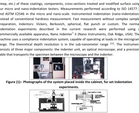
improve absorption in the 300 – 400nm range. The glass transition temperature (Tg) of atactic PMMA is 105°C (221°F). The Tg values of commercial grades of PMMA range from 85 to 165°C (185 to 329°F). The range is so wide because of the vast number of commercial which are copolymer with co-monomers other than methaacrylate. PMMA can be joined using cyano-acrylate cement (commonly known as SuperGlue), with heat (welding) or by using solvents such as di or tri-chloro-methane to dissolve the plastic at the joint, which then fuses and sets, forming an almost invisible weld. Scratches may easily remove by polishing or by heating the surface of the material. PMMA is a strong and lightweight material. It has a density of 1.17 – 1.20g/cm3, which is less than half that of glass. It also has good impact strength, higher than both glass and polystyrene. PMMA transmit up to 92% of visible light (3mm thickness) [11]. The high demands of today’s surfaces and coatings that are engineered to be very hard, very thin or visco-elastic require correspondingly powerful measurement methods and systems. Make quick, precise and effective measurements of mechanical properties (hardness, modulus, creep, etc.) of these coatings, components, cross-sections treated and modified surface using our micro and nano-indentation testers. Measurements performed according to ISO 14577-1 and ASTM E2546 in the micro and nano-scale. Instrumented indentation (nano-indentation) instead of conventional hardness measurement. Fast measurement without complex sample preparation, Indentors: Vickers, Berkovich, spherical, flat punch or custom. The normal indentation experiments described in the current research were performed using a commercially available apparatus, Nano Indenter® II (Nano Instruments, Oak Ridge, USA). The machine uses a compliance indentation system, capable of operating at loads in the microgram range. The theoretical depth resolution is in the sub-nanometer range [12]. The instrument consists of three major components: the indenter unit, an optical microscope, and a precision table that transports the specimen between the microscope and the indenter.

Figure (1):- Photographs of the system placed inside the cabinet, for set indentation experiments.

(5)

Organized by C.O.E.T, Akola, ISTE, New Delhi & IWWA. Available Online at www.ijpret.com22

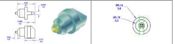
Figure (3):- Schematic representation of the three-sided diamond pyramid, or Berkovich tip. The standard tip is a three-sided diamond pyramid (commonly known as the Berkovich tip), as shown in Figure (4), ground so that the sides of the pyramid make an angle of 65.3° with the normal to the base, Figure (3). Thus the indents appear as equilateral triangles, and the length of a side of a perfectly plastic indent is approximately 7.4 times its depth. A coil is attached to the top of the indenter rod and is held in a magnetic field.

Figure(4):- A nano indenter with its three parts, the diamond, the holder and the bond. BERKOVICH, SHARP 3-SIDED INDENTERS, a = 65.03°, Mod. Berkovich: a = 65.27°

The indenter assembly is suspended on a pneumatic vibration table to isolate it from building vibrations. As mentioned above, the system utilized to apply the load to the indenter consists of a magnet and a coil in the indentation head, and a high precision current source. The current source is applied through the coil in the magnetic field, thus generating a force. The current from the source, after passing through the coil, passes through a precision resistor across which the voltage is measured. During the experiments, a computer controls the voltage source (-10 to +10 V) in order to control the applied normal load. Only the motion of the indenter column as controlled by the load coil is used in the making of an indent as shown in Figure (5).

(6)

Organized by C.O.E.T, Akola, ISTE, New Delhi & IWWA. Available Online at www.ijpret.com23

RESULTS AND DISCUSSIONS

In the making of an indent the ‘surface-finding’ is a basic step, especially when dealing with nano-scale indentations. This system uses a particular procedure to determine accurately the “zero” of the indent, i.e., the values of indenter load and displacement at the point where the tip of the indenter just touches the surface of the sample as shown in nano-instruments operating manual. The system makes a couple of surface-finding indents near the position selected for the initial indent; in this way it establishes an initial estimate of the elevation of the sample surface. Then the table is moved so that the chosen location for the first indent is under the indenter. The indenter is now lowered toward the surface with a user-specified “approach-rate”. The load displacement values are recorded and used to calculate the stiffness of the system, reflected initially in the stiffness of the very flexible leaf springs that support the indenter shaft. When the indenter reaches the surface, a large increase in stiffness is sensed. When stiffness increases by a user-specified factor, approach phase is complete as experimental curve shown in Figure (6).

Figure [6] :- Plot of load versus displacements (expressed in volts), creep dependence for PMMA as a function of hold time (loading and unloading times were maintained constant at

(7)

Organized by C.O.E.T, Akola, ISTE, New Delhi & IWWA. Available Online at www.ijpret.com24

Figure [7]: - Hardness data for PMMA at different holding times; loading and unloading times

were maintained constant at 10s; P/P=0.1s-1. Plot of the ratio of the ‘creeping’ displacement

(occurring during the hold segment) and the maximum displacement, hmax,

The samples were cut using a bandsaw and glued to the sample holder, then screwed to the xy stage. The samples were placed in the cabinet for 24 hours for thermal equilibrium. The following experiment was designed for the PPMA samples, for use with the continuous stiffness option. The loading rates have been selected to provide a full set of data with continuous stiffness option in place. The Approach Segment, 2 x constant leaf spring stiffness, Loading Segment 1, 1 nm per second for 40 nm displacement, Loading Segment 2, 2 nm per second for 80 nm displacement, Loading Segment 3, 4 nm per second for 160 nm displacement, Loading Segment 4, 8 nm per second for 320 nm displacement, Loading Segment 5, 16 nm per second for 640 nm displacement and Loading Segment 6, 32 nm per second for a max force the system can generate. A total of 7 samples were tested with the same experimental procedure. 8 indents were performed on each sample then averaged together for one result for one sample. Figure [7], shows that the lower is the applied maximum load, the higher is the dependence of the normal hardness upon the hold time as should be expected. This is due to the relative weighting that the additional creeping penetration has upon the contact displacement at the contact load, before any creep relaxation occurs, Figure [8]; lower loads produce shallower indentations, which may show a greater relative variation due to the material creep.

Figure (8):- The figure provides data for the Young’s modulus for the PMMA, displacement-time curves for PMMA; (loading and unloading displacement-times were maintained constant at 10s;

P /

P =0.1s-1; holding time was equal to 300s), and contact Contact stiffness data for PMMA.

CONCLUSIONS

(8)

Organized by C.O.E.T, Akola, ISTE, New Delhi & IWWA. Available Online at www.ijpret.com25

advanced technology in quasistatic and dynamic indentation capabilities, plus additional functionality unique to AFM, with the most user-friendly, feature-rich design available in a nanomechanical testing system. This powerful combination results in unprecedented ability from a single tool: high precision demanded for nanoscale investigation along with detailed and accurate nano-scale properties characterization, plus the flexibility, ruggedness, and reliability needed for mechanical testing. With Nano-Force we get nano-mechanical testing capabilities that go far beyond nano-indentation, enabling real innovations in materials science. The hardness and the Young’s modulus of the PMMA were investigated in this research appear to increase at penetration displacements close to the surface. This could be related to a change in the physical and mechanical properties of these systems due to their manufacture or their ageing. Finally, the compliance method appears to be a convenient means for investigating the mechanical properties of polymeric surfaces which often show highly visco-elastic-plastic behaviors during their indentation. The results show that the mechanical properties obtained for these polymers are highly influenced by the testing procedures and the penetration depths utilized. This is particularly evidenced at the penetration depths where the strain rates are extremely high and the physical imperfections of the indenters are of the order of magnitude of the penetrations; particular care is required to reduce the scattered nature and apparent trends of the results under these conditions are reported and trends can be in given Figures above.

REFERENCES

1. Kothari, D.C., “Measurement of the Rheology of pastes”, Ph.D. Thesis, University of London, Imperial College of Science, Engineering, Technology & Medicine, (1999).

2. Lawrence, C.J., Adams, M.J., Briscoe, B.J. and Kothari, D.C., 1998, “Wedge indentation and stress relaxation of a viscoelastic paste”, Proceedings of the Third World Congress on Particle

Technology, Brighton, 588-598.

3. Nano Instrument, Inc, “Nano Indenter operating instructions”, Oak Ridge, 1996.

4. Briscoe, B.J. and Sebastian, K., “The elastoplastic response of poly (methyl methacrylate) to indentation” Proc. Roy. Soc. London, A 452: 439- 457, (1996).

5. Tabor, D, “Indentation Hardness: Fifty years on, A Personal view”, Physical Magazine A, Vol. 74, No. 5: 1207-1212., (1996)

6. Briscoe, B.J., Evans, P.D., Pelillo, E., Sinha, S.K. Wear, 200, (1996). 7. Pelillo, E. PhD Thesis, Imperial College, University of London, (1997).

8. Bowden, P.B. in ‘The Physics of Glassy Pastes’, ed. R.N. Haward, Mat. Sci. Series, Applied Science Pub., London, (1973).

(9)

Organized by C.O.E.T, Akola, ISTE, New Delhi & IWWA. Available Online at www.ijpret.com26

10. Friedrich, K. Journal of Materials Science: Materials in Medicine 4 (1993) 266-272.

11. ISO/IEC 17025 = International standard comprising general requirements for the competence of testing and calibration laboratories, (1992)

Figure

table that transports the specimen between the microscope and the indenter.
Figure (3):- Schematic representation of the three-sided diamond pyramid, or Berkovich tip
Figure [6] :- Plot of load versus displacements (expressed in volts), creep dependence for

References

Related documents

Her feeding intolerance, inconsolability, and gaze aversion character- ized the development of a reactive attachment disorder of infancy in an infant whose mother had withdrawn from

··· Qiang Fu, Zi’ao Ma, Enliang Wang, Tianxiao Li, Renjie Hou 2 (101) Controlling threshold in soil salinity when planting spring wheat and sequential cropping

investigators, managing protocol and regulatory compliance, facilitating the transfer of data, and supporting HALT-PKD activities for quality control, endpoint adjudication, and

Through the inte- gration of application, operating system and architecture level features, our proposed HIDS demonstrates a significant im- provement of the detection rate in terms

When an external lead-acid rechargeable battery is connected to the Strato Pi UPS board, the Raspberry Pi will remain powered by the Strato Pi board when the main power supply