Copyright © 2015 IJECCE, All right reserved
Improving the Impedance Based Fault Location Method
in Distribution Network Considering the Distributed
Generation Unit
Ehsan Gord
Electrical Engineering Department, Faculty of Engineering, Persian Gulf University, Bushehr 7516913817, Iran
Email: [email protected]
Rahman Dashti
Electrical Engineering Department, Faculty of Engineering, Persian Gulf University, Bushehr 7516913817, Iran
Email: [email protected]
Abstract – In this paper an improved impedance based fault location method is proposed. In this method, online fault locating is performed using voltage and current information at the beginning of the feeder. Determining precise fault location in a short time increases reliability and efficiency of the system. The proposed method utilizes information about main component of voltage and current at the beginning of the feeder and distributed generation unit (DGU) in order to precisely locate different faults in acceptable time. To evaluate precision and accuracy of the proposed method a 13-node is simulated and tested using MATLAB.
Keywords – Distribution Network, Fault Section Determination, Distributed Generation Units, Distribution Protection Equipment.
I. INTRODUCTION
Electricity distribution networks, which are the last part of electricity generation transmission and distribution chain, have attracted a great attention recently. In addition to this section, nowadays, renewable energies are becoming increasingly popular due to clean and cheap energy they provide. Therefore, the growth of distributed generation units necessitates considering them in all research works [1]. Fault locating is a prominent issue in power system protection. Precise and accurate fault location considerably decreases non-distributed energy, increases system profitability and increases costumers' satisfactory. There are several factors which make fault location complicated and time consuming. These include widespread network , large number of lateral branches, asymmetry between overhead lines or underground cables (intersection and phase arrangement), distribution transformers in different points and installation of only one data register for fault voltage and current data [2]. Power distribution systems are usually a radial system with unbalanced load. In other words, in power distribution systems, current flows in one direction and different loads are located along a horizontal line [3,4]. Nowadays, however, modern technology and increasing demand for electricity has caused the current system to lack sufficient supply for power demand; thus, to compensate for increasing demand various types of distributed generation units have been utilized in power distribution systems [5]. According to performed research, cost of installation and setup of distributed generation units have been much cheaper than the cost of developing transmission lines. There are further advantages for distributed generation units such that it is anticipated that
distributed generation will constitute considerable portion of power plants [6,7]. Distributed generation systems have many permum, but unfortunately, they have inductions when bechance fault, so distributed generation results in multi-fed distribution system which, in turn, leads to protection problems in power distribution system.As a consequence power generation rate of distributed generation units become slower [8]. Distributed generation units usually depend on renewable energies and various commercial strategies in the industry. Presence of distributed generation units and their generated power changes radial characteristic of the system as there is a new source in the system. In this paper, firstly, steady state analysis of a distribution system without distributed generation in presence of fault is performed in presence of fault and fault location is determined. In the second section, the impacts of distributed generation units are studied and analyzed. In third section the proposed fault location method in the distribution network in presence of distributed generation is completely presented. Finally, fourth section includes simulation and test results.
II. PROPOSED METHOD
Fault location without distributed generation units
Consider the circuit depicted in figure 1. All loads located further than fault location are represented by an equivalent load, 𝑍𝑟 and total current sent to these loads is 𝐼𝐿𝑎. The voltage measured in local terminal (the terminal where data is measured), is obtained from this equation:
𝑉𝑆𝑎 = 𝑥. 𝑍𝐿𝑎𝑎. 𝐼𝑎+ 𝑍𝐿𝑎𝑏. 𝐼𝑏+ 𝑍𝐿𝑎𝑐. 𝐼𝐶 + 𝐼𝑓. 𝑅𝑓(1) (1) 𝑉𝑆𝑎: phase a voltage
x: fault distance
𝑍𝐿𝑎𝑎: Impedance matrix [per km]
𝑍𝐿𝑎𝑏:Impedance between phase a and b
𝑍𝐿𝑎𝑏:Impedance between phase a and c
Copyright © 2015 IJECCE, All right reserved If fault locates in the lateral single phase line, the
voltage equation is as follows:
𝑉𝑆𝑎 = 𝑥. (𝑍𝐿𝑎𝑎. 𝐼𝑎) + 𝐼𝑓. 𝑅𝑓 (2)
Note that voltage equation includes three unknown variables: line distance (x), fault resistance (𝑅𝑓) and fault current (𝐼𝑓). Considering real and imaginary parts of
voltage equation and eliminating fault resistance, the fault distance equation is derived:
𝑥 =𝑉𝑎 𝑟.𝐼𝑓𝑖−𝑉𝑎 𝑖.𝐼𝑓𝑟
𝐴.𝐼𝑓𝑖−𝐵.𝐼𝑓𝑟 (3)
𝐴 = 𝑍𝐿𝑎𝑎 𝑟. 𝐼𝑎𝑟 − 𝑍𝐿
𝑎𝑎 𝑖. 𝐼𝑎𝑖+ 𝑍𝐿𝑎𝑏 𝑟. 𝐼𝑏𝑟− 𝑍𝐿𝑎𝑏 𝑖. 𝐼𝑏𝑖
+𝑍𝐿𝑎𝑐 𝑟. 𝐼𝑐𝑟− 𝑍𝐿𝑎𝑐 𝑖. 𝐼𝑐𝑖
𝐵 = 𝑍𝐿𝑎𝑎 𝑟. 𝐼𝑎𝑖+ 𝑍𝐿
𝑎𝑎 𝑖. 𝐼𝑎𝑟 + 𝑍𝐿𝑎𝑏 𝑟. 𝐼𝑏𝑖+ 𝑍𝐿𝑎𝑏 𝑖. 𝐼𝑏𝑟
+𝑍𝐿𝑎𝑐 𝑟. 𝐼𝑐𝑖+ 𝑍𝐿
𝑎𝑐 𝑖. 𝐼𝑐𝑟
And fault resistance equation is achieved as follows:
𝑅𝑓=
−𝐵. 𝑉𝑎𝑟 + 𝐴. 𝑉𝑎𝑖 𝐴. 𝐼𝑓𝑎𝑖− 𝐵. 𝐼𝑓𝑎𝑟
(4)
(r,i) subscript denotes real and imaginary part and (𝐼𝑓) can
be calculated using the relation between load current and line current.
𝐼𝑓 = 𝐼𝑎+ 𝐼𝐿𝑎 (5)
Equations 3 and 5 are valid for phase to ground fault of decoupled power system. Equations for other fault conditions such as phase to phase, phase to ground and three-phase, might be obtained through the same procedure.
In this paper the following algorithm is employed to estimate fault location:
a) 𝐼𝐿𝑎is assumed to be the main load current before fault occurrence.
b) Equation 5 is used to estimate fault current. c) Equation 3 estimates fault location.
At this step convergence of x is checked. If x converges, it is sent for print; otherwise, the algorithm repeats once more.
d) Equation 6 calculates voltage of estimated point.
𝑉𝑆𝑎 𝑉𝑆𝑏 𝑉𝑆𝑐
=
𝑉𝑓𝑎 𝑉𝑓𝑏 𝑉𝑓𝑐
– x .
𝑍𝐿𝑎 . 𝐼𝑆𝑎 𝑍𝐿𝑏 . 𝐼𝑆𝑏 𝑍𝐿𝑐 . 𝐼𝑆𝑐
) 6(
e) Using the fault voltage calculated in the previous step a new load current is calculated
f) Using the derived load current, algorithm is repeated again from step B
In the described algorithm in step c, it is necessary to calculate system current which is obtained through circuit analysis. As shown in figure 1, it is easy to derive the current after fault point when voltage in fault point (which is estimated), equivalent load and line impedance are known. Moreover, various line models might be utilized to estimate new load described in equation 5.
If the algorithm converges, fault is estimated wherever it is in the distribution system. In each step of fault location using this algorithm, Vsa and Isa are updated for the next step. Updating these values decreases faults associated with line loss and topology of power system distribution
components which are resulted from different loads in the line.
Considering figure 2, updated voltage and current are obtained according to equations 7 to 9.
Fig.2. Updated voltage and current in local terminal
𝑉𝑘+1= 𝑉𝑘− 𝑍𝑘. 𝐼𝑘 (7)
𝐼𝐿𝑘 = 𝑉𝑘. 𝑌𝐿𝑘 (8)
𝐼𝑘 = 𝐼𝑘 −1− 𝐼𝐿𝑘 (9)
Updating voltage and current, the algorithm restarts and the new fault point is determined more precisely. This procedure continues till convergence is achieved in the estimation fault location.
III. EFFECTS OF DISTRIBUTED GENERATION
UNITS
Problems associated with connection of power generation equipment in distribution systems arise in different aspects: stability, voltage regulation, system stability and so on. Some of these problems such as voltage sags due to high current protection include several fields of study [9].
The most prominent effect of distributed generation units in power distribution systems is variations in system power flow. Power distribution systems with radial power flow are not radial anymore in presence of distributed generation units. In system protection plan this characteristic must be considered in cases including equipment protection coordination and proper selection. Furthermore, fault current, phase angle and current in different parts of supply line may change. The portion of distributed generation from total power generation can change fault current in many sections of the feeder. Besides, magnitude and direction of fault current depend on power supplied by distributed generation units and their location in the system.
Copyright © 2015 IJECCE, All right reserved Determining the effects of distributed generation units
on distribution systems described in section 3, a more precise descriptive model of the system could be obtained. For distributed generation units a machine model must be used to precisely specify the status including effects of distributed generation units and facilitates fault location estimation with acceptable precision. Furthermore, distributed generation units must be considered in updated voltage and current states because their injected power depends on the power flows in the system.
IV. THE PROPOSED METHOD FOR F
AULTLOCATING IN PRESENCE OF DISTRIBUTED
GENERATION UNIT
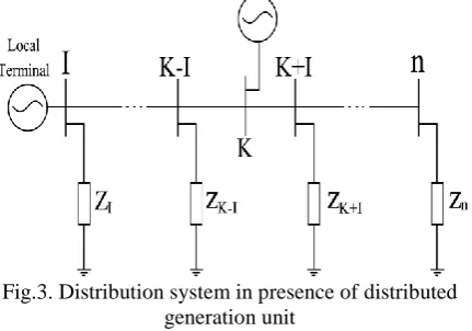
Consider a distribution system in presence of distributed generation unit:
Fig.3. Distribution system in presence of distributed generation unit
As illustrated in the figure, the side before the source is connected to nodes 1 to k-1 and the next section is related to nodes k+1to n. the proposed fault locating algorithm considering source starts through steps A to F explained in section 2. The algorithm starts while it considers the fault at the beginning of the supply line i.e. before the source. a) 𝐼𝐿𝑎is assumed to be the load current before fault occurrence
b) Equation 5 is used for fault current calculation.
c) Fault distance is estimated using equation 3. Then convergence is checked and in case of convergence, the calculated value is sent for print; otherwise, the algorithm is repeated.
d) fault point voltage is calculated using equation 6, for this purpose the system inclduing distributed generation unit explicated in section 5, is considered. Station voltages and currents for stations before fault location are calculated.
According to figure 2, fault point voltage is derived from undergoing equation.
𝑉𝑓 = 𝑉𝑛−1− 𝐼𝑛 −1. 𝑍𝑙𝑖𝑛𝑒. 𝑥 (10)
Where Zline is line impedance per 1 kilometer of faulty line and x is the distance from n-1 station to fault point. e) Using fault point voltage obtained in the previous step, total system Thevenin equivalent circuit is derived in two following states.
e.1. if the fault location estimated in step 3 is after generation unit, equivalent circuit is shunt to loads mixed
by line impedance after fault point. At this time current is updated again (with updated current and voltage values belonging to the first station before fault point). This current is obtained from the following equation.
𝐼𝐿𝑎 =
𝑉𝑓
𝑉𝑡 (11)
e.2. in contrast if fault location is before distributed generation unit, thevenin equivalent circuit includes power supply in the feeder. In this circumstance, new load current is derived from the equation below.
𝐼𝐿𝑎 =
𝑉𝑓−𝑉𝑡
𝑍𝑡 (12)
d) Algorithm returns to step b. similar to what explained for distribution systems without distributed generation units, the outputs of this algorithm are distance of fault from the beginning of distribution system feeder. To achieve higher precision considering load distribution and loss of distribution lines, it is required to update voltages and currents measured in local terminals to restart algorithm again and another point must be estimated. This update continues till more precise voltages and currents are derived and supply line terminates.
V. DESCRIPTIVE MODEL OF DISTRIBUTED
GENERATION
The electrical model of distributed generation unit in this study is synchronous generator model demonstrated in figure 4.
Fig.4. Distributed generator model
This model is a combination of 𝑋𝑆′′(transient reactance), ra (armature resistance) and 𝐸𝑔′′ (internal voltage) for synchronous generator.
VI. SIMULATION AND RESULTS
13-node three-phase system shown in figure 5 is simulated using MATLAB software. Loads are modeled as constant impedances.
Copyright © 2015 IJECCE, All right reserved In table 1 fault percentage in different feeders is
calculated with negligible error and table 2 fault percentage in fault starting angles is calculated.
Fig.5. 13 node distribution system with distributed generation unit
A-
Effect of Sections Difference
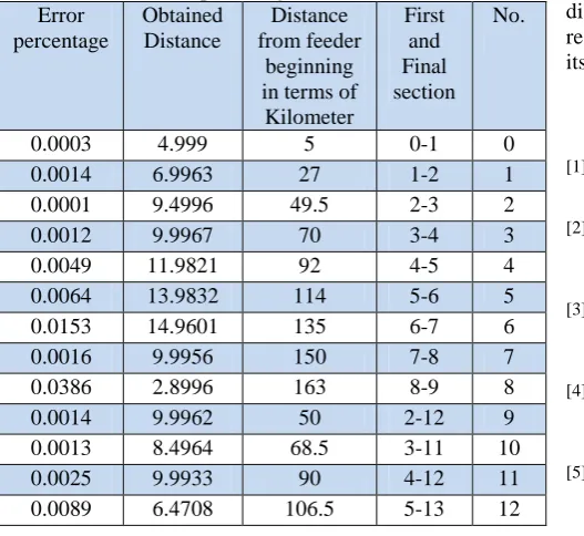
By changing the fault section, accuracy is reduced. In other words, the ultimate accuracy is reduced. But, As proposed algorithm has been developed, So changes in difference fault distance in difference sections do not effect on performance of the proposed algorithm.The Results are shown in table [1] confirms this fact.
Table I: Error percentage in different feeders Error
percentage
Obtained Distance
Distance from feeder
beginning in terms of
Kilometer
First and Final section
No.
0.0003 4.999 5 0-1 0
0.0014 6.9963 27 1-2 1
0.0001 9.4996 49.5 2-3 2
0.0012 9.9967 70 3-4 3
0.0049 11.9821 92 4-5 4
0.0064 13.9832 114 5-6 5
0.0153 14.9601 135 6-7 6
0.0016 9.9956 150 7-8 7
0.0386 2.8996 163 8-9 8
0.0014 9.9962 50 2-12 9
0.0013 8.4964 68.5 3-11 10
0.0025 9.9933 90 4-12 11
0.0089 6.4708 106.5 5-13 12
B-
Effect of Fault Inception Angle
Because proposed algorithm works based on voltage and current at the beginning of feeder, changes in voltage angle even smallest one, have no considerable effect on algorithm performance. Therefore proposed algorithm has an acceptable performance for voltage angles. Table [2] has summarized results for simulation of fault with different starting angles.
Table II: Error percentage in different fault starting angles Error
Percentage
Fault Starting Angle
Faulty Section
No.
0.00442 0.8525 Fault in
distributed generation unit feeder
1
0.01096 0.855 2
0.20142 0.8575 3
0.95288 0.86 4
0.02357 0.8625 5
0.00846 0.865 6
0.93811 0.8675 7
1.322 0.87 8
VII. CONCLUSION
In this paper a novel method was presented for fault location in radial distribution systems in presence of distributed generation units. It locates fault based on voltage and current samples of feeder and DGU register. In the impedance based proposed method all sections of distribution systems are investigated to find fault location, first, based on voltage and current information before fault occurrence. Then, all sections are examined based on information registered in the location of main supply after fault occurrence.
Single phase to ground fault was simulated on 13-node distribution system in MATLAB software. The obtained results revealed that the proposed algorithm is precise and its sensitivity to different fault distances is ignorable.
REFERENCES
[1] RahmanDashti, “fault locating in power distribution systems using adaptive algorithm”, PhD thesis (Dissertation), electrical engineering- power systems, 2013
[2] W.Y. Huang, et al, "Equivalent circuits for an SLG fault distance evaluation by curve fiting in compensated distribution systems", IEEE Transactions on power Delivery, vol. 23, no. 2, pp. 601-608, 2008.
[3] J. Mora-Flòrez, J. Meléndez, G. Carrillo-Caicedo, ''Comparison of impedance based fault location methods for power distribution systems", Electric Power Systems Research, vol. 78, pp. 657– 666, 2008.
[4] R. H. Salim, M. Resener, A. D. Filomena, K. RezendeCaino de Oliveira, A. S. Bre-tas, "Extended fault-location formulation for power distribution systems", IEEE Transactions on Power Delivery, vol. 24, pp. 508–516, 2009.
[5] R. Dashti and J. Sadeh, "Accuracy improvement of impedance based fault location method for power distribution network using distributed-parameter line model", European Transactions on Electrical Power (ETEP) Journal, vol. 24, no. 3, pp. 318-334, 2014.
[6] R. Dashti and J. Sadeh, "Applying Dynamic Load Estimation and Distributed-parameter Line Model to Enhance the Accuracy of Impedance based Fault-location Methods for Power Distribution Networks", Electric Power Components and Systems, vol. 41, no. 14, pp. 1334-1362, 2013.
[7] R. Dashti and J. Sadeh, " Fault section estimation in power distribution network using impedance-fault distance calculation and frequency spectrum analysis", IET Generation, Transmission & Distribution, vol. 8, no. 8, pp. 1406-11417, 2014.
Copyright © 2015 IJECCE, All right reserved
[9] R. Dashti and J. Sadeh, "Accuracy improvement of impedance based fault location method for power distribution network using distributed-parameter line model", European Transactions on Electrical Power (ETEP) Journal, vol. 24, no. 3, pp. 318-334, 2014.
[10] R. Dashti and J. Sadeh, "Applying Dynamic Load Estimation and Distributed-parameter Line Model to Enhance the Accuracy of Impedance based Fault-location Methods for Power Distribution Networks", Electric Power Components and Systems, vol. 41, no. 14, pp. 1334-1362, 2013.
AUTHOR’S PROFILE
Ehsan Gord
was born in Bushehr, Iran, on September19, 1982. He received the M.bc. in electrical engineering from Azad University of Bushehr, Iran, in 2006.He is a Senior student in power electrical engineering of Persian Gulf University, Iran. His research interests are distribution system, include fault diagnosis in power systems, neural network computing, power electronics, Electric machines, renewable energy, and harmonic analysis.
Rahman Dashti