http: // www.ijrtsm.com© International Journal of Recent Technology Science & Management 12
ISSN : 2455-9679
[Ashish et al. , 4(5), May 2019] Impact Factor : 2.865
IJRTSM
INTERNATIONAL JOURNAL OF RECENT TECHNOLOGY SCIENCE & MANAGEMENT
“LINEAR WELDING PROCESS OPTIMIZATION BY DESIGN & MANUFACTURING SPECIAL
PURPOSE MACHINE”
Ashish Malviya
1,
Vaibhav Jain
2, Vikas Sharma
31 M.Tech. Scholar, Dept. of Mechanical Engineering, Malwa Institute Of Technology, Indore, MP, India
2-3 Assistant Professor, Dept. of Mechanical Engineering, Malwa Institute Of Technology, Indore, MP, India
ABSTRACT
In industry, process optimization is used to increase productivity and work accuracy. The welding process used for making silencer is done manually which leads to less accuracy and a time consuming process which also affects cost of productivity and machining time. The prime objective is coming out with this cause to increase productivity by introducing a mechanism or a fixture that hold a job for welding a cylindrical entity and electric motor driven mechanism for accurate welding. This project includes study, testing & development of various concepts for the optimized result. Tests are based on time, cost & vibration. Production time and cost of manufacturing is major part in his project and vibration analysis will ensure that welding gets accurate.
Keyword: Linear Welding, SPM (Special Purpose Machine)
I. INTRODUCTION
Modern age is the age of science, with dawn of 18th century industrialization and globalization came into picture. During pre-industrial era the machine were seldom used and almost 80-90% of the operations were performed manually. Thus there was an increase in demand of the products while the supply was less. This led to the use of machine in industries, and industrialization came into existence.
The industrialization also gave rise to the competition, almost all the industries began to use machines, to increase their market share and to reach out to more and more people. With the use of machines, more reliable products were produced, as compared to the conventional manual method. Automobile and manufacturing sector experienced a significant change in the world market. The process which took many days to complete manually can now be completed in few minutes, with the help of automated machines.
http: // www.ijrtsm.com© International Journal of Recent Technology Science & Management 13
ISSN : 2455-9679
[Ashish et al. , 4(5), May 2019] Impact Factor : 2.865
II. OBJECTIVE
The primary objective for this project can be describe to develop a special purpose machine for linear welding and handling metal sheet in cylinder form. So worker can handle and weld efficiently.
Earlier the same operation was done by manual process which is involved more people to perform operation and also have more setup time and handling time. By the installation of special purpose we can perform welding operation faster, this machine will reduce not only the setup time, handling time but also extra workers are eliminated, this will improve efficiency and reduced cost for operation.
III. CONCEPTULIZATION
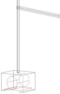
3.1 Concept 1
Torch Mounting over Dial Gauge Stand and Forward Movement using Leadscrew Actuation Concept
Basic idea of this design is developed by setup used in metrology lab for inspection purpose to holding dial gauge indicator, welding torch at a place of dial gauge can be held for rigidity while welding operation. This concept is further analyzed for advantages as well as disadvantages purpose and we found some flaws as well as some idea for finalizing design of our welding torch holding structure.
Advantages
Compact design
Small setup gives less cost for manufacturing
Less complexity
Disadvantages
Less robust design
Vibration cause torch angle to deviate
Maintenance cost is high as structure is very flexible
Torch fixture is unable to sustain load on it and easily get moved
Welding machine and torch assembly is difficult to synchronize
http: // www.ijrtsm.com© International Journal of Recent Technology Science & Management 14
ISSN : 2455-9679
[Ashish et al. , 4(5), May 2019] Impact Factor : 2.865
3.2 Concept 2
Bridge Setup with Upper Moving Assembly
As per the flexibility concern previous design is very in compatible to satisfy all demands of operation so that we have designed a setup for holding welding torch and achieving all demands
°rees of freedom of machined.
In this design we have formulated a setup of torch at height of fixture cylinder. To sustain as forces over the setup, the setup of bridge is made up of 50X50 squares bar, lead screw supported by two guide rod of Lm specification used to support torch mounting plate and the whole setup is fixed inside slot provided on the square bar.
The whole structure have all degrees of freedom required for welding operation and suitably adjust torch setup in machine, motor mounted co-axially to the lead screw and supported by motor mounting plate and connected with lead screw using coupling.
Advantage
Robust design
Possible to achieve all degrees of freedom
Feasible torch mounting
Flexibility in cylinder change can be easily achieved
Limitations
Very heavy design
Weight is very high.
Compact ability of setup is less.
Two operator required to change setup
Centre alignment is not possible
High space required
Torch angle is difficult to achieve
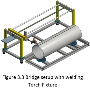
Concept 3
Bridge setup with welding Torch Fixture Construction
Due to so many limitations design 2 has been rejected to overcome flaws in design we decided to design new welding fixture which is capable of taking any angle for welding remaining setup is same.
Figure 3.2 Bridge Setup with Upper
Moving Assembly
http: // www.ijrtsm.com© International Journal of Recent Technology Science & Management 15
ISSN : 2455-9679
[Ashish et al. , 4(5), May 2019] Impact Factor : 2.865
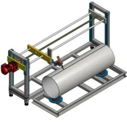
Concept 4
Compact Bridge Assembly Construction
In this setup, we replace 50X50mm metal bar with 50X50X3 mm square tube and setup is reduced in width. Compact & light weight design is manufactured & all disadvantages of previous design is overcome. After evaluation of all concept (Concept-1 to Concept-3) with their advantages and Disadvantages we finalized Concept-4. Now we are going to work on Concept-4 and perform analysis on it.
VI. DESIGN & ANALYSIS
As per concept-4 for linear welding fixture main work piece fixture frame is situated in bottom and attached with base frame. Workpiece is supported by Boxnut to fix over fixture frame. Welding torch is guided by a guide road and a lead screw. Lead screw is running though a electric motor.
Linear welding is kind of very precise welding on if welding torch is deviate with any frequency it would lead a imprecise welding so we need to check frequency of machine with respect to natural frequency of electric motor.
Figure4.1 Complete Assembly
Figure4.2 First order vibration
modal displacement nephogram
http: // www.ijrtsm.com© International Journal of Recent Technology Science & Management 16
ISSN : 2455-9679
[Ashish et al. , 4(5), May 2019] Impact Factor : 2.865
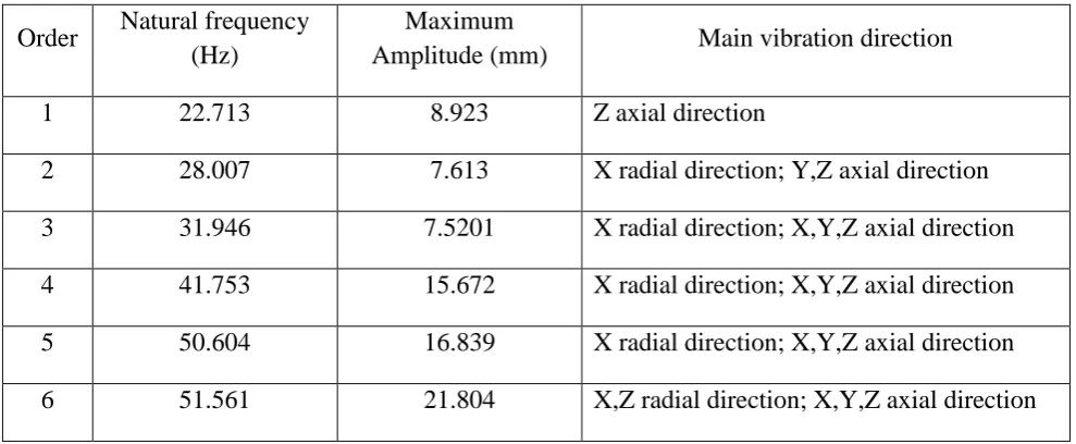
Table: 4.1 Modal analysis results of SPM
Order
Natural frequency
(Hz)
Maximum
Amplitude (mm)
Main vibration direction
1
22.713
8.923
Z axial direction
2
28.007
7.613
X radial direction; Y,Z axial direction
3
31.946
7.5201
X radial direction; X,Y,Z axial direction
4
41.753
15.672
X radial direction; X,Y,Z axial direction
5
50.604
16.839
X radial direction; X,Y,Z axial direction
6
51.561
21.804
X,Z radial direction; X,Y,Z axial direction
Figure4.4 Third order vibration
modal displacement nephogram
Figure 4.5 Fourth order vibration
modal displacement nephogram
Figure4.6 Fifth order vibration
modal displacement nephogram
http: // www.ijrtsm.com© International Journal of Recent Technology Science & Management 17
ISSN : 2455-9679
[Ashish et al. , 4(5), May 2019] Impact Factor : 2.865
Since frequency of machine is differed from natural frequency of motor, then the chances of resonance is avoided automatically and we don’t have need to prevent these vibration through dampers. This vibration range is also helps in accuracy in welding which reduce extra machining time.
So for the vibration point of view concept 4 is justified and can be forward to manufactured and install.
V. RESULT
Performance Analysis:5.1Conventional Operation Calculation
Time required for welding
Total time for welding operation = Machine time + Setup Time + Handling Time Total time for welding operation = 2.30 + 1 + 0.30
Total time for welding operation = 4 Minutes
Production
Number of components produced in One day
= No. of Shift * Time per shift * No. of component produced per hour = 1 * 8 * 15
= 120 units / day
Number of components produced in 30 day = 120*30
= 3600 units / Month
5.2 Operation on Special Purpose Machine
Time required for welding
Total time for welding operation = Machine time + Setup Time + Handling Time Total time for welding operation = 0.50 + 1 + 0.30
Total time for welding operation = 2 Minutes 20 Seconds
Production
Number of components produced in One day
= No. of Shift * Time per shift * No. of component produced per hour = 1 * 8 * 25.71
= 205 units / day Approx
Number of components produced in 30 day = 120*30
= 6150 units / Month
Number of extra Component produced in a month = 6150 – 3600 = 2550 units Increase in efficiency due to Special Purpose Machine
http: // www.ijrtsm.com© International Journal of Recent Technology Science & Management 18
ISSN : 2455-9679
[Ashish et al. , 4(5), May 2019] Impact Factor : 2.865
VI. CONCLUSION AND FUTURE SCOPE
6.1 Conclusion
The project has been successfully completed and SPM designed and manufacturing serves the purpose of aiding of the automation in horizontal welding.
The purpose of this project is to give the high efficiency by converting manual welding process to automated welding process and reduce labour as well as handling cost and achieve higher productivity in time efficient manner.
6.2 Future Scope
Mobility can be achieved as well as flexibility can be increased.
Using pneumatic setup we can check leakage in cylinder and also advancement in the sensor can be used to achieve precise length sensing.
Can increase sensibility for operational accuracy.
Advancement in welding by using pneumatic cylinder and tacking operation can be possible with association with horizontal welding.
By adding special attachment in fixture we can roll cylinder in the placing of cylinder over fixture so that to reduce operational time very high.
We can add engraving machine to embossing the part no so as to identify the leakages and manufacturing defect.
Video recording of the total welding process so as to identify where defects has been induced.
REFERENCES
1. Arianna Elefante “Detecting beam offsets in laser welding of closed-square-butt joints by wavelet analysis of an optical process signal”. Optics and Laser Technology, Volume 109, Pages 178–185, 2019.
2. Jigar D Suthar “Design and analysis of fixture for welding an exhaust impeller”. Procedia Engineering, Institute of Technology, Nirma University, Ahmedabad, Volume 51, Pages 514 – 519, 2013.
3. R.F. Hamade “Nondestructive detection of defects in friction stir welded lap joints using computed tomography”, Materials and Design, Volume 162, Pages 10–23, 2019.
4. Abhishek Das “Fixture Design Optimisation Considering Production Batch of Compliant Non-Ideal Sheet Metal Parts”. Procedia Manufacturing Volume 1, Pages 157–168, 2015.
5. R. Förstmann “Design for Automation: The Rapid Fixture Approach”. Procedia Manufacturing, Volume 11, Pages 633 – 640, 2017.
6. Baowei Ma “Integration process of stamping for DP600 advanced high strength steel sheets”. Procedia Manufacturing, Volume 15, Pages 684 – 692, 2018.
7. Anil Akdogan “Investigation of Effects (Welding Sequence, Fixturing, Welding Points) on Distortions after Spot Welding for Determining Individual and Cumulative Tolerances”. IFAC (International Federation of Automatic Control) – PapersOnLine, Volume 49-29, Pages 30–35 2016.
8. R. Fritzsche “Automatic adjustment of car body fixtures using artificial intelligence”. Procedia CIRP, Volume 62, Pages 600 – 605, 2017.
9. Florian Schlather “Process forces during remote laser beam welding and resistance spot welding”. Procedia CIRP, Volume 74, Pages 669–673, 2018.
http: // www.ijrtsm.com© International Journal of Recent Technology Science & Management 19
ISSN : 2455-9679
[Ashish et al. , 4(5), May 2019] Impact Factor : 2.865
11. J. Ahn “Determination of residual stresses in fibre laser welded AA2024-T3 T-joints by numerical simulation and neutron diffraction”. Materials Science & Engineering, Volume A 712, Pages 685–703, 2018.