Vol. 3, No. 2, pp. 103-114, April (2020)
A New Power Swing Detection Method Based on
Hilbert Transform
Sirus Salehimehr
1, Behrooz Taheri
2, Seyed Amir Hosseini
3, Hossein Askarian Abyaneh
4, †, and Farzad
Razavi
51 Young Researchers and Elite Club, Qazvin Branch, Islamic Azad University, Qazvin, Iran.
2 Faculty of Electrical, Biomedical and Mechatronics Engineering, Qazvin Branch, Islamic Azad University, Qazvin, Iran.
3 Department of Electrical Engineering, Golpayegan University of Technology, Isfahan, Iran.
4Department of Electrical Engineering, Amirkabir University of Technology, Tehran, Iran, +982164543370
5 Faculty of Electrical, Biomedical and Mechatronics Engineering, Qazvin Branch, Islamic Azad University, Qazvin, Iran.
The paper proposes a new method based on Hilbert transform to detect power swings and faults occurring during them. The proposed method operates independently from the system parameters. As well, it can detect different types of power swings, including stable, unstable, and multi-mode power swings, and can also differentiate the power swing from the faults for blocking or unblocking the distance relay. In order to evaluate the proposed method, various types of power swing and simultaneous faults are simulated in the DIgSILENT software package. Then, using the matrix data obtained from the current signals, the proposed algorithm is implemented in the Matlab software package using the Hilbert transform. The results show that the proposed method can detect different types of power swings successfully. In addition, it is shown that the proposed method operates very fast. Besides, when a fault occurs simultaneously with the power swing, it unblocks the relay as soon as possible. This method is also implemented practically on a distance relay and is tested by a relay tester device made by Vebko Amirkabir Knowledge-Intensive Company. The results obviously show that the proposed method operates better than conventional industrial methods.
Article Info
Keywords:
Power swing, Power system protection. Distance relay,Hilbert transform. Article History:
Received 2019-03-25
Accepted2019-09-01
I.
I
NTRODUCTIONEnergy transmission lines play a vital role in transmission systems. Since nearly 85-87% of the possible faults in power systems occur in these lines, their protection becomes more important [1-2]. Due to the capability of distance relays for displaying the fault location, as well as the creation of high-level protective zones, these relays are widely used in high voltage (HV) and ultra-high voltage (UHV) transmission lines. The reliability of distance relays can be obtained when they retain their stability during the faults occurring outside of their
protective zones, and also they should not operate for the occurrence of un-faulted disturbances that reduce the impedance calculated by them [3]. The unwanted operation of distance relays in the HV and UHV transmission lines may cause the cascading outage of the transmission lines, and as a result, blackouts may occur in power networks, imposing irreparable damages to power transmission companies and consumers [4]. One of the most challenging disturbances that can cause mal-operation of distance relays is the power swing phenomenon. The power swing may impose destructive effects on power systems in various ways, such as damage to the protective equipment or the mal-operation of distance relays. Due to these destructive effects, proper and fast detection of
†Corresponding Author: [email protected]
Department of Electrical Engineering, Amirkabir University of Technology, Tehran, Iran.
A
B
S
T
R
A
C
power swings is particularly important in protection systems. When a power swing occurs, the amplitude of the voltage is decreased by increasing the amplitude of the current signal. Thus, the impedance seen by the relay decreases, and in this case, the distance relay detects this condition as a fault, so a trip command can be issued by the relay [5]. In order to prevent the operation of distance relays during power swings, a power swing blocking (PSB) function is used in these relays. So far, numerous studies have been carried out on the power swing phenomenon and various algorithms to detect it. This section examines a variety of PSB techniques and characterizes the advantages and shortcoming of the techniques.
The most commonly used method for detecting power swings and enabling the PSB function is to evaluate the rate of changes in impedance that travels through the specified region [6]. The disadvantage of this method is the failure to detect the symmetrical faults that occur simultaneously with a power swing. A method based on the swing center voltage (SCV) is presented in [7-9]. The SCV-based schemes use the V cos(θ) to detect power swings and their differentiation from the simultaneous faults, where V is the amount of voltage at the relay location and θ is the angle between the voltage and current signals at the relay location. Because of the generation of electromagnetic transients during the faults, the wavelet transform scheme for analyzing the transient states in power systems is introduced in some studies, including articles [10-12]. One of the most common shortcomings of the available power swing detection techniques is the differentiation of the three-phase faults from power swing conditions. In fact, the detection of three-phase faults is a challenge for all detectors due to their symmetrical nature. On this basis, a method based on the asymmetrical component value of fault inception is presented in [13] to detect the faults occurring during a power swing. A threshold value is also considered for this method and as soon as the asymmetric component becomes bigger than the threshold value, the fault is detected and the algorithm unblocks distance relay.
The rate of instantaneous frequency change in a power system is proposed in [14] for fast detection of power swings and the discrimination between the power swing simultaneous faults. A strength of this method is its ability to detect unstable power swings. In addition, there is a low volume of computations in this scheme, which makes it appropriate to be used in industrial relays. Despite its advantages, the method has also some drawbacks, such as high sensitivity to noise and poor performance when a multi-mode power swing occurs. The researchers in [15] have used the RMS value of the current signal to differentiate power swings and faults. The proposed algorithm using the RMS value of the current signal is capable of fast blocking the relay during a power swing. Furthermore, this method can discriminate various types of faults from power swings. The most important disadvantage of this method is that it operates with a remarkable delay for
simultaneous faults. In [16], a sample estimation and error calculation method based on Taylor series has been used for fast detection of power swings. All low impedance faults can be detected by the proposed method in this paper. However, it operates incorrectly for high impedance faults and may block the relay after the occurrence of this type of fault. The support vector machine (SVM) is introduced in [17] to enhance the accuracy of differentiating power swings from the faults in the power system. This scheme is very fast for distinguishing the faults during a power swing. The main problem of the methods that use the SVM technique is that they need a lot of offline simulation to train the various types of faults and power swings. The power swing detection in series-compensated lines and its challenges have been studied in [18]. A new scheme based on the combination of covariance of current signals using the cumulative approach is presented in [19] for discriminating between the power swings and faults. The schemes proposed in [20, 21] use mathematical morphology-based methods to discriminate between faults and power swings. Due to the use of sophisticated mathematical relations, the practical implementation of these methods is challenging. The researchers in [22] have introduced an algorithm for PSB function based on moving window averaging of the current signal. This method can detect different types of faults occurring simultaneously with a power swing. In addition, the method detects both stable and unstable power swings. The most important shortcoming of this method is inappropriate operation when a multi-mode power swing occurs. In [23], the rate of variations in the average value of apparent power is used to solve the PSB function problem. Various types of power swings such as stable, unstable, and multi-mode power swing can be detected by this method. This method operates incorrectly for a high-impedance fault condition. In [24], the power swing occurrence is analyzed. By defining transmission lines and generators sensitivities coefficients, a way is found to make the line under full load. It is discussed how to minimize the distance between load impedance and the last zone of distance protection, and the settings of the power swing relays are calculated.
simultaneous faults were simulated in the DIgSILENT software package and then using the matrix data obtained from the current signal, the proposed method was implemented in the Matlab software package using Hilbert transform. The method presented here was evaluated against the standard 39-bus test system for various types of power swing conditions and faults occurring during the power swing. The results obtained from simulations using the proposed method show the accuracy of this method for detecting various types of power swings including stable, unstable, and multi-mode power swings. In addition, the proposed method is capable of detecting the faults during power swings correctly. The proposed method was also implemented on a distance relay and was tested by a relay tester device, both made by Vebko Amirkabir Knowledge-Intensive Company. The results obviously show that the proposed method operates better than conventional industrial methods.
The paper is organized as follows. Section II discusses the proposed method and its performance for power swings and the discrimination between power swings and faults using Hilbert transform. In Section III, the proposed method is evaluated. On this basis, the proposed method is tested and evaluated against a standard 39-bus test system in different types of power swings and simultaneous faults. This method is also implemented on a distance relay and is tested by a relay tester device. Section IV compares the proposed method with other available methods, and the results demonstrate the applicability of the proposed method.
II.
P
ROPOSED METHODWhen a power swing occurs in a power network, a significant change happens in voltage and current signals. Since the power swing is a symmetrical phenomenon, the changes in the three phases of the electrical signals are the same. On the other hand, when a fault occurs in a power network, this symmetry is violated at the inception of the fault. This paper uses the Hilbert transformation to differentiate power swings and faults for blocking or unblocking the distance relay. To use this scheme for distinguishing between power swings and faults, at first, each phase should be sampled separately using a moving data window whose length can be obtained by Eq. (1).
s
F
Window length
F
(1)where Fs is the sampling frequency (according to the
industrial digital relays, the sampling frequency used in this paper is 10 kHz), and Ff is the fundamental frequency of the
system that is equal to 60 Hz. After sampling each phase in each window length, a matrix will be formed according to Eq. (2)-(4).
1, ,...,
2
a i
M
a a
a
(2)
1, ,...,
2
b i
M
b b
b
(3)
1, ,...,
2
c i
M
c c
c
(4)In digital relays, after the sampling of the signal, it is essential to analyze the obtained data obtained by signal processing. For this purpose, the Hilbert transform is used in this paper. The Hilbert transform is a type of unified transforms (such as Laplace and Fourier) that was first introduced by David Hilbert in this setting to solve the property of integral equations in physics and mathematics. The Hilbert transform for the function X(t) is defined as follows [25-26].
1
( )
[
( )]
( )
x
H X t
x t
d
t
(5)To apply the Hilbert transform to discrete data, the following four-step algorithm is used in this paper:
1. Calculate the FFT for input data according to the following equation and save the result on the vector x:
1
2 /
0
N
i kn N
K n
n
X
x e
(6)2. Create a vector h whose elements h(i) have the values of:
1 for
1, ( / 2) 1
2 for
2, 3,..., ( / 2)
0 for
( / 2)
2,...,
i
n
i
n
i
n
n
(7)
3. Calculate the element-wise product of x and h
4. Calculate the inverse FFT of the sequence obtained in Step 3 which returns the first n elements of the result.
After applying the Hilbert transform to the output signal, the following equation is obtained:
( )
Real
Image
x t
j
(8)Afterward, the RMS value of the signal in Eq. (8) is calculated using Eq. (9).
2 1
( )
N kx t
RMS
N
(9)Fig. 1. Rate of changes of current signal during the power swing and simultaneous fault.
As it is evident in Figure (1), the variations of all three phases are equal during power swings. However, at the time of the fault occurrence at the third second, the variations obtained from the three phases are different from one another. To use this feature to discriminate between fault and power swing, the variation rate in each phase should be extracted from Eq. (10).
( ) ( 1) ( )
1... 1
I n I n I n
for n L
(10)
Based on what was already mentioned and the calculation of variation rate using Eq. (10), the condition for identifying the power swing is designed as below.
If ( )
Power swing will be detected
else
Fault will be detected
Ia Ib Ic
(11)
Therefore, when the impedance seen by the distance relay enters into its protective zones, the condition defined in Eq. (11) will be checked. Based on this condition in the proposed algorithm, the activation of the PSB function performs when the rate of variations in all three phases of the current signal is the same. In contrast, when the impedance seen by the distance relay enters the protective zones and the condition of the algorithm is not satisfied, a fault will be detected and in this case, the relay will be unblocked. It should be noted that the proposed algorithm will work as long as the impedance remains in the protection zones of the distance relay, and once a fault occurs during a power swing, the condition of the algorithm will be violated and as a result, the fault can be detected by the proposed algorithm.
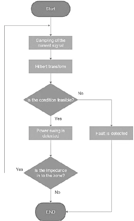
It is, therefore, clear that the proposed method has the necessary conditions as a comprehensive detector for detecting power swings. This means that this method is capable of detecting power swings and faults occurring during power swings rapidly and easily. According to what was mentioned, Figure (2) depicts the proposed algorithm for the detection of
power swings and faults occurring simultaneously with power swings.
Fig. 2. The algorithm of the proposed method.
III.
T
ESTING OF THE PROPOSED METHODA. Introduction of the sample network
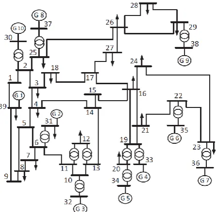
This paper uses an IEEE standard 39-bus test system to evaluate and test the proposed method. The single-line diagram of the network is displayed in Figure (3) [27]. This network consists of 39 buses and 10 generators. The available loads of the network consume 6150.1 MW of active power and 1233.9 MVar of reactive power.
Fig. 3. The single-line diagram of IEEE standard 39-bus test system.
TABLEI
LINE PARAMETER
Line Length Current Resistance Reactance
26-29 247.96 km 1 kA Ohm/km 0.02736 Ohm/km 0.3
B. Evaluation of power swing condition
In order to evaluate the performance of the proposed method in detecting power swings, the proposed algorithm is tested by simulating on a sample network (Figure 3) in three case studies.
1) Case study 1: Stable Power swing: As already mentioned, the power swing occurs when the rotor angle of the generators, in response to a large variation in load, line switching, loss of excitation of the generator, and faults is leading or lagging than together. In this case, if disturbances do not occur severely and the system reaches a new balanced state, a stable power swing will occur. In this section, to simulate the stable power swing condition on line 26-29, the parallel lines 26-28 and 28-29 are isolated from the network by the circuit breakers in 0.5 seconds. The operation of the proposed algorithm in the stable power swing condition is shown in Figure (4). As illustrated in this figure, the stable power swing is detected in 30 milliseconds by the proposed algorithm and the relay is blocked.
Fig. 4.( (a) Current signal during stable power swing;
Fig. 4.( (b) The Hilbert transform of the current signal;
Fig. 4.(c) The operation of the proposed algorithm during the stable power swing.
2) Case study 2: Unstable Power swing: The unstable power swing condition occurs when the occurrence of disturbances mentioned in the previous section cause a generator or a group of generators to experience pole slip. To simulate the unstable power swing condition on line 26-29, a large load with an active power of 1500 MW and a reactive power of 2000 MVar is applied on bus No. 26 in 0.5 seconds by switching. Normally, the PSB algorithms in a distance relay should detect unstable power swings and block the relay operation. As illustrated in Figure (5), the proposed algorithm successfully detects this type of power swing and blocks the relay operation.
Fig. 5.( a) Current signal during the unstable power swing;
Fig. 5.(b)The Hilbert transform of the current signal;
Fig. 5.(c) The operation of the proposed algorithm during the unstable power swing.
transform, the operation of the proposed algorithm for the multi-mode power swing is illustrated in Figure (6 (c)). As shown in this figure, the multi-mode power swing is correctly detected by the proposed algorithm at 30 milliseconds and the PSB function is activated.
Fig.6.(a) Current signal during multi-mode power swing;
Fig.6.(b) The Hilbert transform of the current signal;
Fig.6.(c) The operation of the proposed algorithm during the multi-mode power swing.
C. Evaluation of simultaneous faults with power swing
As already mentioned, in addition to power swings, the PSB algorithms should also be able to detect the faults that occur simultaneously with the power swing. On this basis, the proposed algorithm is designed in such a way that it remains activated until when the impedance is into the third zone of the relay, and the condition determined in Eq. (4) is continuously evaluated. In this case, as soon as a fault occurs during a power swing, the determined condition is violated in fault inception and the fault is detected by the algorithm and as a result, the relay is unblocked. To evaluate these situations, this section tests different types of simultaneous faults in four different scenarios.
1) Case study 1: Single-phase fault simultaneously with the power swing: To simulate the power swing on the line 28-29, the parallel lines are isolated from the network at 0.5 seconds. Then, a single-phase fault to the ground is applied on 50% of the line 28-29 at 3 seconds. The variations of the current signal for this condition is shown in Figure (7(a)), and its output by applying the Hilbert transform is illustrated in Figure (7(b)). As well, the operation of the proposed algorithm for simultaneous single-phase fault is shown in Figure (7 (c)). According to Figure (7 (c)), when a power swing occurs, the PSB function blocks the relay from tripping, and as soon as a fault occurs during a power swing, the algorithm detects it in 30 milliseconds and unblocks the relay.
Fig.7.(a) Current signal during the power swing and simultaneous single-phase earth fault;
Fig.7 .(b) The Hilbert transform of the current signal;
Fig.7. (c) The operation of the proposed algorithm during the power swing and simultaneou single-phase earth fault.
2) Case study 2: Three-phase fault simultaneously with the power swing: As mentioned earlier, the discrimination between the power swing and three-phase fault is one of the most important challenges with PSB algorithms due to their symmetrical nature. However, this problem is solved by determining the appropriate condition in the proposed method by using the fault inception of all permanent faults. Hence, due to exceeding the rate of changes in the current signal from the threshold during a fault simultaneously with the power swing, the determined condition is violated and therefore the relay is unblocked. Figure (8) represents the measured current signal (8 (a)), the Hilbert transform of the current signal (8 (b)), and the operation of the proposed method (8 (c)) during a power swing and a three-phase with the same time with the previous case. As shown in Figure (8(c)), when a power swing occurs in a power system, the PSB function is started and blocks the relay from the tripping, and as soon as a three-phase fault occurs, it is detected by this algorithm and the relay is unblocked.
Fig.8. (a) Current signal during the power swing and simultaneous three-phase fault
Fig.8. (b) The Hilbert transform of the current signal
Fig.8 (c) The operation of the proposed algorithm during the power swing and simultaneous three-phase fault.
determined condition of the proposed algorithm is violated, and as a result, the algorithm can detect the fault correctly.
Fig.9. (a) Current signal during the power swing and high impedance fault;
Fig.9. (b) The Hilbert transform of the current signal
Fig.9. (c) The operation of the proposed algorithm during the power swing and high impedance fault.
4) Case study 4: Three-phase fault during the power swing with white Gaussian noise: In electrical engineering and signal processing, white noise is referred to as a signal that affects all the frequency components of a signal equally. It is called "white" because the density function of its power spectrum is almost constant at all frequencies (like white light). The correlogram function of white noise is as a Dirac delta function. White noise is inherently a stochastic process. Therefore, it is a statistical model for signals and signal sources, not a specific signal. White noise is also referred to as any discrete-time signal whose samples are followed by stochastic variables that have a mean zero and finite variance. Depending on the application, samples may need to be considered independently and distributed with the same probability distribution [29].
Gaussian white noise can have adverse effects on signals. These undesirable effects can cause the wrong operation of the PSB algorithms. On this basis, this section uses white Gaussian noise to investigate the operation of the proposed algorithm during a stable power swing and simultaneous three-phase fault during the power swing. Figure (10) shows the white Gaussian noise added to the power swing and fault occurring during the power swing conditions.
Fig.10. White Gaussian noise added to the power swing and simultaneous fault condition.
To simulate the power swing and simultaneous fault, the events mentioned in Section 3.3.2 are applied to the system. Afterward, white Gaussian noise is added to the current signal. As shown in Fig. (11), the stable power swing with the white Gaussian noise is successfully detected by the proposed algorithm and the relay is correctly blocked. Besides, when a fault occurs during a power swing, the algorithm detects it and unblocks the relay.
Fig11. (a) Current signal during the power swing and simultaneous three-phase fault with white Gaussian noise
Fig11. (b) The Hilbert transform of the current signal with white Gaussian noise
Fig11. (c) The operation of the proposed algorithm during the power swing and simultaneous three-phase fault with white
Gaussian noise.
5) Investigation of the proposed method at a power angle of 180 degrees: In Fig. (12), the current of one of the phases during a power swing is shown and the corresponding power angle is specified. As can be seen, the power angle reaches 180 degrees when the current is at its maximum value during the swing.
amplitude (as compared to other conditions) is not significant. This is problematic in some methods. Another point is that, at a power angle of about 180 degrees, the impedance location calculated by the relay is on the transmission line characteristic, meaning that impedance cut-off is inside the relay protection zone. In this condition, if a fault occurs, it is difficult to detect it by some methods because the impedance location does not change significantly.
Fig.12. Current signal during power swing and its related power angle.
For instance, the simulation results for the fault in 90% of lines during a power swing are shown in Fig. (13). This is one of the worst possible scenarios because the amplitude of fault current is approximately equal to the maximum power swing current.
Fig.13. (a) Current signal during the unstable power swing and simultaneous three-phase faul
Fig.13. (b) The Hilbert transform of the current signal
Fig.13. (c) The operation of the Investigation of the proposed method at a power angle of 180 degrees.
IV.
P
RACTICAL TESTINGTo practically test the proposed method, the algorithm is implemented on a real-time distance relay and is also tested by a relay tester device, both made by Vebko Amirkabir Knowledge-Intensive Company. The distance relay used for the test is of the AMR type. The proposed method is also compared with SIPROTEC 4 distance protection 7SA522 made by the Siemens Co.
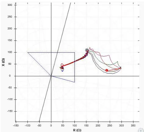
Figure (14) shows the test setup for testing the PSB function of the distance relay using the proposed algorithm in this paper. To perform this test, the power swing condition extracted from the simulated network in the DigSILENT software package is converted into a COMTRADE file and uploaded onto the tester software to evaluate the algorithm for power swing and fault conditions. The impedance trajectory for this situation is illustrated in Figure (15). In this case, by entering the impedance into the third zone of distance relay during the power swing, the algorithm will be started and since the condition stated in Eq. (4) is satisfied, the power swing is detected. Also, when a fault occurs during the power swing, the condition is violated and the fault is thus detected.
Fig.14. The test setup for testing of the proposed method.
Tables (2) and (3) present the results for the comparison of the proposed method with the conventional industrial methods presented in [30-32]. This comparison is performed using practical testing in different scenarios such as stable, unstable, and multi-mode power swings, as well as single-phase and three-phase faults simultaneously with the power swing. Both methods are tested in the same conditions with the same type of relay. Also, different types of injected faults by the relay tester device are the same so that the results can be compared accurately.
As can be seen in Tables (2) and (3), the conventional industrial methods detect power swings in approximately 100 milliseconds. However, the method proposed in this paper detects power swings in the same condition in about 30 milliseconds. Also, the conventional industrial methods show a different performance for simultaneous faults. This means that for the several tests in the same condition, different detection times are recorded by this method.
V.
C
OMPARISON WITH AVAILABLE METHODSVarious methods have been developed for detecting symmetrical faults during power swings. Each method has its own signal processing tools and sampling frequency, so they detect power swings and simultaneous faults at different times. Some of the most common methods for power swing detection are compared with the proposed method, and the results are shown in Table (4).
In addition to detecting the symmetrical three-phase fault, the algorithm of the PSB function faces other challenges including the detection of simultaneous high-impedance fault and also correct operation when noise is created in a signal. Accordingly, Table (5) compares the methods presented in other articles and the proposed method with a focus on some conditions including the high-impedance fault, multi-mode power swing, and current signal with noise. As is evident in Table (4), the methods presented in other papers have the problem of detecting high-impedance faults. Also, when noise is created on the current signal, they cannot operate correctly.
However, it can be seen that our proposed method can detect power swings and simultaneous faults even in these mentioned conditions.
VI.
C
ONCLUSIONThis paper presented an efficient high-reliability method for the detection of power swings and faults that occur simultaneously with the power swings. In the proposed method, the Hilbert transform is used to obtain the rate of variations in the current signal. Since the rate of the variations in three-phase of the current signal is the same during the power swings and when a fault occurs, the rate of the variations in the three phases is different from one another. Thus, according to this concept and by determining a threshold value, it is possible to distinguish between the rate of variations during power swings and simultaneous faults. The proposed method is evaluated by various types of power swings including stable, unstable and multi-mode power swings as well as various types of simultaneous faults including single-phase and three-phase faults. The results of the evaluations prove that the proposed method can detect power swings and faults occurring during power swings very fast. In addition, unlike the other PSB algorithms, this method is less complex, which makes it possible to implement it in the structure of protective relays. The proposed method is compared with the conventional industrial methods and most common available PSB techniques, whose results show that the proposed method performs better. This method was also implemented practically on a distance relay and was tested by a relay tester device. The results obviously show that the proposed method performs better than conventional industrial methods.
A
CKNOWLEDGMENTThe authors would like to thank Vebko Amirkabir Company for providing a protection relay and a relay tester device.
TABLEII
THE RESULTS OF TESTING FOR THE CONVENTIONAL INDUSTRIAL METHOD PRESENTED IN [30-32].
Test Type Power swing
Detection
Fault Detection test during power swing
Time of power swing detection(ms)
Time of fault detection(ms)
Stable Power Swing Yes - 103.8 -
Unstable Power Swing Yes - 104.4 -
Multi-mode power swing No - - -
Single-phase fault during Power Swing Yes Yes 107 126.6
Two phase fault during power swing Yes Yes 108 127.8
Two phase to ground fault during power swing Yes Yes 105 129
Three-phase fault during Power Swing Yes Yes 104.1 120
TABLEIII
THE RESULTS FOR TESTING OF THE PROPOSED ALGORITHM.
Test Type Power swing
Detection
Fault Detection test during power swing
Time of power swing detection(ms)
Time of fault detection(ms)
Stable Power Swing Yes - 32 -
Unstable Power Swing Yes - 33 -
Multi-mode power swing Yes - 32 -
Single-phase fault during Power Swing Yes Yes 33 32
Two phase fault during power swing Yes Yes 32 32
Two phase to ground fault during power swing Yes Yes 32 33
Three-phase fault during Power Swing Yes Yes 34 33
High Impedance fault during power swing Yes Yes 32 32
TABLEIV
COMPARISON WITH OTHER METHOD
TABLEV
COMPARISON BETWEEN THE EXISTING METHODS AND THE PROPOSED METHOD
The operation of methods with noise in
signal Detection of
multi-mode power swing Detection of high
impedance fault Method Reference number No No Yes Instantaneous frequency [14] No Yes Yes RMS [15] No No No Moving window averaging
[38]
No No
No Rate of change of admittance
[37] No No No FFT [35] No No No Prony [36] YES YES YES HILBERT
PROPOSED METHOD
R
EFERENCES[1] B. Panigrahi and R. Maheshwari, "Transmission Line Fault Detection and Classification," IEEE Proceeding of ICETECT, 2011.
[2] B. Taheri, S. A. Hosseini, H. Askarian-Abyaneh, and F. Razavi, "A New Method for Remote Testing Distance Relay Using Internet Protocol Version 4," in 2019 International Conference on Protection and Automation of Power System (IPAPS), 2019, pp. 31-37: IEEE.
[3] E. Udren et al., "Proposed statistical performance measures for microprocessor-based transmission-line protective relays. I. Explanation of the statistics," IEEE Transactions on Power Delivery, vol. 12, no. 1, pp. 134-143, 1997.
[4] S. Zubić, P. Balcerek, and Č. Zeljković, "Speed and security improvements of distance protection based on Discrete Wavelet and Hilbert transform," Electric Power Systems Research, vol. 148, pp. 27-34, 2017.
[5] B. Mahamedi, "A very fast unblocking scheme for distance protection to detect symmetrical faults during power swings," in IPEC, 2010 Conference Proceedings, 2010, pp. 378-383: IEEE.
[6] J. Blackburn, "Protective Relaying Principles and Applications 2nd Edition New York Basel Marcel Dekker," ed: Inc, 1998. [7] P. S. R. Committee, "Power swing and out-of-Step
considerations on transmission lines," in IEEE Power Engineering Society, 2005.
[8] N. Fischer, G. Benmouyal, D. Hou, D. Tziouvaras, J.
Byrne-Asymmetrical fault detection Symmetrical fault detection
Sampling freq.(KHz) Method Reference number Yes No 2 Rate of change of power
[32] Yes Yes 1 Automatic regression [33] Yes No 1 FFT [34] Yes No 3 Prony [35] Yes Yes 40.96 Wavelet [10] Yes Yes 10 Travelling wave [12] Yes Yes 1 Rate of change of admittance
[36]
Yes No
1 Moving window averaging
Finley, and B. Smyth, "Do system impedances really affect power swings—Applying power swing protection elements without complex system studies," in Protective Relay Engineers, 2012 65th Annual Conference for, 2012, pp. 108-119: IEEE.
[9] P. K. Nayak, J. G. Rao, P. Kundu, A. Pradhan, and P. Bajpai, "A comparative assessment of power swing detection techniques," in Power Electronics, Drives and Energy Systems (PEDES) & 2010 Power India, 2010 Joint International Conference on, 2010, pp. 1-4: IEEE. [10] S. M. Brahma, "Distance Relay With Out-of-Step Blocking
Function Using Wavelet Transform," IEEE Transactions on Power Delivery, vol. 22, no. 3, pp. 1360-1366, 2007. [11] R. Dubey and S. R. Samantaray, "Wavelet singular
entropy-based symmetrical fault-detection and out-of-step protection during power swing," IET Generation, Transmission & Distribution, vol. 7, no. 10, pp. 1123-1134, 2013.
[12] C. Pang and M. Kezunovic, "Fast distance relay scheme for detecting symmetrical fault during power swing," IEEE Transactions on Power Delivery, vol. 25, no. 4, pp. 2205-2212, 2010.
[13] C. Lazaro, J. Marques, G. Marchesan, and G. Cardoso, "Waveform asymmetry of instantaneous current signal based symmetrical fault detection during power swing," Electric Power Systems Research, vol. 155, pp. 340-349, 2018.
[14] B. Taheri, S. Salehimehr, F. Razavi, and M. Parpaei, "Detection of power swing and fault occurring simultaneously with power swing using instantaneous frequency," Energy Systems, pp. 1-24, 2019.
[15] B. Taheri and F. Razavi, "Power Swing Detection Using rms Current Measurements," Journal of Electrical Engineering & Technology, vol. 13, no. 5, pp. 1831-1840, 2018. [16] I. G. Tekdemir and B. Alboyaci, "A novel approach for
improvement of power swing blocking and deblocking functions in distance relays," IEEE Transactions on Power Delivery, vol. 32, no. 4, pp. 1986-1994, 2017.
[17] N. G. Chothani, B. R. Bhalja, and U. B. Parikh, "New support vector machine-based digital relaying scheme for discrimination between power swing and fault," IET Generation, Transmission & Distribution, vol. 8, no. 1, pp. 17-25, 2014.
[18] P. K. Nayak, A. K. Pradhan, and P. Bajpai, "A fault detection technique for the series-compensated line during power swing," IEEE transactions on power delivery, vol. 28, no. 2, pp. 714-722, 2013.
[19] M. H. Musa, Z. He, L. Fu, and Y. Deng, "A covariance indices based method for fault detection and classification in a power transmission system during power swing," International Journal of Electrical Power & Energy Systems, vol. 105, pp. 581-591, 2019.
[20] A. Morais, G. C. Júnior, L. Mariotto, and G. Marchesan, "A morphological filtering algorithm for fault detection in transmission lines during power swings," Electric Power Systems Research, vol. 122, pp. 10-18, 2015.
[21] M. Daryalal and M. Sarlak, "Fast fault detection scheme for series-compensated lines during power swing," International Journal of Electrical Power & Energy Systems, vol. 92, pp. 230-244, 2017.
[22] J. G. Rao and A. K. Pradhan, "Power-swing detection using moving window averaging of current signals," IEEE Transactions on Power Delivery, vol. 30, no. 1, pp. 368-376, 2014.
[23] B. Taheri, F. Razavi, and S. Salehimehr, "Power Swing
Detection Using the Variation Rates of the Average Value of Apparent Power," in 2019 International Conference on Protection and Automation of Power System (IPAPS), 2019, pp. 38-43: IEEE.
[24] Abyaneh, H. Askarian, M. Marjanmehr, and M. Meshkin. "Stability analysis for power swing protection." 2004 5th Asian Control Conference (IEEE Cat. No. 04EX904). Vol. 3. IEEE, 2004.
[25] S. L. Hahn, Hilbert transforms in signal processing. Artech House, 1996.
[26] M. Feldman, "Hilbert transform in vibration analysis," Mechanical systems and signal processing, vol. 25, no. 3, pp. 735-802, 2011.
[27] M. Pai, Energy function analysis for power system stability. Springer Science & Business Media, 2012.
[28] S. Hashemi, M. Sanaye-Pasand, and M. Shahidehpour, "Fault Detection During Power Swings Using the Properties of Fundamental Frequency Phasors," IEEE Transactions on Smart Grid, 2017.
[29] A. shamsi, "Reconfigurable CT QDSM with mismatch shaping dedicated to multi-mode low-IF receivers," International Journal of Industrial Electronics, Control and Optimization, vol. 2, no. 3, pp. 257-264, 2019.
[30] S. SIPROTEC, "Distance Protection 7SA522 V4. 70," instruction manual, 2011.
[31] J. Blumschein, Y. Yelgin, and M. Kereit, "Proper detection and treatment of power swing to reduce the risk of Blackouts," in Electric Utility Deregulation and Restructuring and Power Technologies, 2008. DRPT 2008. Third International Conference on, 2008, pp. 2440-2446: IEEE.
[32] G. Ziegler, Numerical distance protection: principles and applications. John Wiley & Sons, 2011.
[33] X. Lin, Y. Gao, and P. J. I. T. o. P. D. Liu, "A novel scheme to identify symmetrical faults occurring during power swings," vol. 23, no. 1, pp. 73-78, 2008.
[34] J. G. Rao and A. K. J. I. t. o. p. d. Pradhan, "Differential power-based symmetrical fault detection during power swing," vol. 27, no. 3, pp. 1557-1564, 2012.
[35] X. Lin, Y. Gao, and P. Liu, "A novel scheme to identify symmetrical faults occurring during power swings," IEEE Transactions on Power Delivery, vol. 23, no. 1, pp. 73-78, 2008.
[36] S. Lotfifard, J. Faiz, and M. Kezunovic, "Detection of symmetrical faults by distance relays during power swings," IEEE transactions on power delivery, vol. 25, no. 1, pp. 81-87, 2010.
[37] S. M. Hashemi, M. Sanaye-Pasand, and M. Shahidehpour, "Fault Detection During Power Swings Using the Properties of Fundamental Frequency Phasors," IEEE Transactions on Smart Grid, pp. 1-1, 2018.
Sirus Salehimehr was born in Qazvin, Iran, in 1993. He received his MSc degree in Power System Engineering with high honors from Islamic Azad University(IAU), Qazvin, Iran, in 2019. He is currently a research assistant at Vebko Amirkabir Knowledge-based Co. His research interests include power system protection, Transient in Power System and Smart grid. He has been a Member of Young Researchers and Elite Club, Qazvin Branch, Islamic Azad University, since 2018.
Behrooz Taheri born in Qazvin, Iran, in 1993. He received the B.S. degree in electrical power engineering in 2015. He is received his MSc degree in Electrical Engineering with high honors from Qazvin Islamic Azad University (QIAU), Qazvin, Iran, 2018. He is currently doing his Ph.D. at QIAU under Dr. Farzad Razavi. In 2015, he joined the Vebko Amirkabir Knowledge-Intensive Company, as a Consultant of chief executive officer in the education and research field. He is a Member of Iran’s National Elites Foundation since 2019. He has also been a Member of young researchers and elite club since 2018. His research interests include power system protection, Transient in Power System, Microgrid, and Smart grid.
Seyed Amir Hosseini was born in Golpayegan, Iran, in 1986. He received the B.S. degree in electrical power engineering in 2009. He received the M.S. degree in electrical engineering from Tafresh University, Markazi, Iran in 2013. He received the Ph.D. degree in electrical power engineering with Department of Electrical Engineering, Amirkabir University of Technology, Tehran, Iran in 2017. He is currently an Assistant Professor of electrical engineering with Golpayegan University of Technology, Isfahan, Iran. His research interests include power system protection, power system analysis, optimization, and smart grids.
Hossein Askarian Abyaneh received his B.S. degree from Iran University of Science and Technology in 1976 and M.S. degree from Tehran University, Tehran, Iran, in 1982, both in electrical engineering. He received a second M.S. degree and the Ph.D. degree, both in power engineering, from the University of Manchester Institute of Science and Technology, Manchester, U.K., in 1985 and 1988, respectively. Currently, he is a Professor with the Department of Electrical Engineering, Amirkabir University of Technology, Tehran, Iran. He has published numerous scientific papers in reviewed journals and presented at international conferences. His research interests include power system protection and power quality.