RESEARCH LETTER
Current structure and flow pattern
on the electron separatrix in reconnection
region
Ruilong Guo
1,2*, Zuyin Pu
2and Yong Wei
1Abstract
Results from 2.5D Particle-in-cell (PIC) simulations of symmetric reconnection with negligible guide field reveal that the accessible boundary of the electrons accelerated in the magnetic reconnection region is displayed by enhanced electron nongyrotropy downstream from the X-line. The boundary, hereafter termed the electron separatrix, occurs at a few de (electron inertial length) away from the exhaust side of the magnetic separatrix. On the inflow side of the
electron separatrix, the current is mainly carried by parallel accelerated electrons, served as the inflow region patch of the Hall current. The out-of-plane current density enhances at the electron separatrix. The dominating current carriers are the electrons, nongyrotropic distribution functions of which contribute significantly to the perpendicular electron velocity by increasing the electron diamagnetic drift velocity. When crossing the separatrix region where the Hall elec-tric field is enhanced, electron velocity orientation is changed dramatically, which could be a diagnostic indicator to detect the electron separatrix. In the exhaust region, ions are the main carriers for the out-of-plane current, while the parallel current is still mainly carried by electrons. The current density peak in the separatrix region implies that a thin current sheet is formed apart from the neutral line, which can evolve to the bifurcated current sheet.
Keywords: Magnetic reconnection, Separatrix region, Electron separatrix, Diamagnetic current, Electron nongyrotropy, Finite gyroradius Effect
© The Author(s) 2017. This article is distributed under the terms of the Creative Commons Attribution 4.0 International License (http://creativecommons.org/licenses/by/4.0/), which permits unrestricted use, distribution, and reproduction in any medium, provided you give appropriate credit to the original author(s) and the source, provide a link to the Creative Commons license, and indicate if changes were made.
Background
Magnetic reconnection is a key process in space plasmas to change magnetic topology and accelerate and heat particles. The reconnection region is separated into two inflow regions and two outflow regions by four separa-trices together with the X-line. The separatrix is a region where the field and plasma quantities are different from those of the inflow region and outflow region. The fea-tures and strucfea-tures of the separatrix region at the mag-netopause have been observed by Cluster (Khotyaintsev et al. 2006; Retinò et al. 2006; Lindstedt et al. 2009). These observations mainly recorded the magnetospheric branch of the separatrix region at tens of di (ion inertial
length) away from the X-line. They showed density cavity,
strong electric field, electron beams, intense waves, and potential jump existing in the separatrix region, suggest-ing that the separatrix is highly structured, especially on the low-β side in the asymmetric case. Waves (e.g., low/ upper hybrid waves, Langmuir waves, electrostatic soli-tary waves, and whistler waves) are found and surveyed in separatrix region (Farrell et al. 2002; Drake et al. 2003; Viberg et al. 2013; Fujimoto 2014). In addition, tem-perature anisotropy has been shown to occur in both the inflow region and separatrix region in simulation results (e.g., Cattell et al. 2005; Egedal et al. 2012) and observations (e.g., Chen et al. 2009; Egedal et al. 2008,
2010, 2012). A large-scale parallel electric field is pro-posed to lead to this temperature anisotropy by heating the electrons in the parallel direction to form elongated electron velocity distribution functions (eVDFs) (Egedal et al. 2012), and similar eVDFs have been observed and compared with the simulation results (Egedal et al.
2010, 2012; Wang et al. 2016). The beam-type eVDF is a
Open Access
*Correspondence: [email protected]
significant feature in the separatrix region as well (e.g., Cattell et al. 2005; Chen et al. 2008; Hwang et al. 2013), which can provide free energy to stimulate waves. The parallel beams have also been confirmed and studied in the magnetopause reconnection region by investigat-ing the recent MMS (Magnetospheric Multiscale) data (e.g., Hwang et al. 2016; Phan et al. 2016). Electron non-gyrotropy/agyrotropy is another important characteris-tic in the electron diffusion region (EDR) and separatrix region. To illustrate the nongyrotropic property of the electrons, several parameters such as electron agyrotropy
AΦe (Scudder and Daughton 2008), the local degree of
nongyrotropy Dng (Aunai et al. 2013), and Q-parameter
for the measure of gyrotropy (Swisdak 2016) have been proposed. All these parameters are enhance inside and outside of EDR (e.g., Aunai et al. 2013; Shuster et al. 2015; Nakamura et al. 2016; Swisdak 2016). The nongyrotropic properties are significant in the asymmetric reconnection region, which is related to the crescent distribution gen-erated by the finite gyroradius effect (Hesse et al. 2014; Burch et al. 2016; Hesse et al. 2016; Norgren et al. 2016; Shay et al. 2016).
The understanding of magnetic reconnection dynamics in space relies on the technique of resolving kinetic pro-cesses within the region where the plasmas are decoupled from the magnetic field. Of notable values to reconnec-tion research are the electron-scale layers of the out-of-plane current density (Jy, here we define y-axis is along
the current flow direction, i.e., the out-of plane direc-tion, while z-axis is perpendicular to the current sheet, and x-axis is along the background magnetic field) and the electric field normal to the current sheet (Ez), as the
simultaneous enhancements of these two quantities may indicate an encounter of the electron diffusion region (EDR) according to Particle-in-cell (PIC) simulation stud-ies (Fujimoto 2006; Chen et al. 2008; Drake et al. 2008), and in situ measurements (Chen et al. 2008). Recently, several reconnection diffusion regions have been identi-fied and investigated with the high cadence MMS meas-urements (e.g., Burch et al. 2016; Burch and Phan 2016; Hwang et al. 2016). Notable thin out-of-plane current sheet and out-of-plane accelerated electron flow have been recorded at dayside magnetopause to define the EDR (Burch et al. 2016; Chen et al. 2016). The general-ized Ohm’s law can also be studied by analyzing the MMS data, and the results showed that the divergence of elec-tron pressure tensor significantly contributes to in-plane and reconnection electric fields (Torbert et al. 2016). The previous PIC studies showed that enhancements of Jy and Ez can also occur near the separatrices away from the
EDR (e.g., Aunai et al. 2013; Shuster et al. 2015). In addi-tion, Runov et al. (2003, 2006) found bifurcated current sheet distributions in the magnetotail by Cluster, which
is suggested to be related to the magnetic reconnection. The bifurcated current structure is also reproduced by global MHD simulation by Thompson et al. (2006). The current density peak of the bifurcated current sheet does not coincide with the neutral line, and it is generally sug-gested that it is related to the Hall effect currents gen-erated in separatrix region (e.g., Runov et al. 2003). The complicated current system may be also related to the reconnection front current structures (Yao et al. 2013), in which parallel current density is carried by electrons (Yao et al. 2016), and perpendicular currents are mainly carried by ions (Yao et al. 2017). These studies imply that the current system in the separatrix region is an essential element in the reconnection process.
In this paper, we present results from a PIC simula-tion of symmetric reconnecsimula-tion with zero guide field to address the formation of thin current sheet in the separa-trix region and the associated electron/ion flow pattern. The finite gyroradius effect on the electron separatrix leads to electron nongyrotropy and increases the out-of-plane velocity, thereby enhancing the Hall effect. From the viewpoint of fluid, the thin current sheet on separa-trix is mainly maintained by the electron diamagnetic drift.
Simulation model
The 2.5D PIC simulation in this paper uses open boundary conditions (Daughton et al. 2006, 2009). The simulation starts with an equilibrium Harris cur-rent sheet with zero guide field. The initial magnetic field is Bx(z)=B0tanh(z/L), where L denotes the
half-width of the current sheet and B0 is the asymptotic
value of the magnetic field. The initial number density is n(z)=n0sech2(z/L)+nb, where n0 and nb repre-sent the maximum density in the center of the Harris current sheet and the background density, respec-tively. The simulation domain is Lx×Lz=80di×20di, containing 10,240 × 2560 cells with 600 particles per cell, where di =c/ωpi is the ion inertial length based on n0. Other initial parameters are the mass
ratio mi/me = 400, temperature ratio Ti/Te = 5, L/di = 0.5, nb/n0 = 0.05, and the ratio between the
electron plasma frequency and cyclotron frequency
ωpe/ωce=2. Reconnection is initiated by adding a per-turbation δB [δBx = −δ2
L x
Lz
cos2π (x−L0.5Lx)
x
sinπLz
z
,
δBz=δBsin 2
π (x−0.5Lx) Lx
cosπLzz, more details in
Daughton et al. (2009)] to the initial magnetic field. The reconnection rate reaches its peak of ~0.17 at
t = 18.5ωci−1, where ωci is the ion cyclotron frequency
determined by B0. The eVDFs are calculated in spatial
inertial length using n0. The velocity is normalized by
the ion Alfvén speed VA based on the initial asymptotic
magnetic field B0 and Harris sheet density n0, yielding VA = 1/40 c.
Simulation results and discussion
The magnetic separatrix field lines are marked by white lines with Ay = Ay (X) in Fig. 1 (Ay is the Y-component of
magnetic vector potential, and X is the coordinate of the
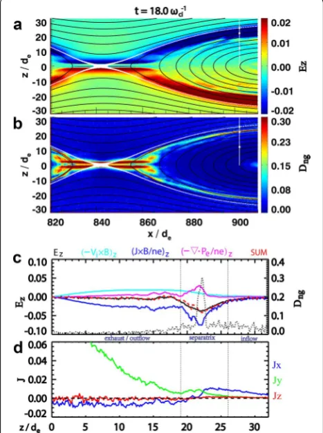
X-line at [x, z] ~ [842,0]de located by the saddle point of Ay). The data are from t = 18ωci−1, at around the time of the
peak reconnection rate. The two inflow regions are at top and bottom, while the exhaust regions (where accelerated electrons can be expelled) are at the left and right sides of the plot. At this point of time, a primary island exists
at the left of the X-line (not shown). The right exhaust region is open, i.e., no island exists on this side, so the electrons can be freely expelled out of this region. Here, we zoom in to discuss the open exhaust on the right side, but the physics addressed in this paper can be applied to the island side exhaust as well. Figure 1a shows the color contours Ez to illustrate the Hall electric field around the
separatrix. Figure 1b shows another important parameter for both EDR and separatrix, the local degree of electron nongyrotropy Dng=2
ijNij2/Tr(Pe) [Nij is the
nongy-rotropic elements of the full electron pressure tensor Pe , see Aunai et al. (2013)]. Two parallel bands of enhanced
Ez and Dng outline the EDR centered at the X line (Fig. 1a,
b). The electron nongyrotropy in EDR has been discussed by other authors (e.g., Scudder and Daughton 2008; Aunai et al. 2013; Shuster et al. 2015), which is not the major concern in this paper. Both Ez and Dng extend from
near the end of the EDR, and diverge away from the z = 0 plane (neutral plane) roughly along the magnetic sepa-ratrix field lines. Later, we will show that the enhance-ment of Ez along separatrix line marks the region where J × B term dominates, which is defined as the separatrix region in this paper (the detailed definition of the separa-trix region are introduced later). Hence, the enhanced Ez
region can approximately represent the separatrix region in the 2D contour plot. The magnetic separatrix is inside the separatrix, implying that the Hall effect can extend outside of the magnetic separatrix. In addition, we will show that the enhanced Dng region along magnetic
sep-aratrix line marks the boundary of the accelerated elec-trons, which is consistent with the previously reported electron separatrix (e.g., Lindstedt et al. 2009).
To show the properties in the separatrix region at downstream of the X-line, Fig. 1c, d shows the plot of the terms in Ohm’s law and current density, respectively, along the intercept marked as the white vertical line in Fig. 1a, b (as it is roughly symmetric to neutral plane, here we only show the z > 0 domain to make the pic-ture clear). The intercept is at x = 902de, approximately
3di away from the X-line. In Fig. 1c, black solid curve
shows the intercept of Ez, and Dng is denoted by black
dotted curve. The colored curves represent the z -com-ponents of the terms in the generalized Ohm’s law (elec-tron inertial term is neglected because of their negligible contributions):
The force balance result shows that the Hall term
J×B/ne is greater than other terms, and is consistent
with previous PIC results showing that Ez is primarily
balanced by the −Ve×B term (combination of −Vi×B (1) ⇀
E+V⇀×⇀B= ⇀ J ×⇀B
ne − ∇ ·←P→e
ne Fig. 1 Simulation results of the magnetic reconnection separatrix
region. a, b color contours for Ez and local degree of nongyrotropy
(Dng). The z-axis is perpendicular to the current sheet, x-axis is along the background magnetic field, and y-axis is in the out-of-plane direc-tion to complete the right-handed orthogonal coordinate system. White thick curve lines represent the separatrix field lines. Black curves are in-plane magnetic field lines (Ay contours). Bx is positive for z > 0. Hall field Ez and Dng are enhances in separatrix layers. c Terms in generalized Ohm’s law at the intercepts of x = 902de. Red dashed lines
and the Hall term) across the separatrix within sev-eral di from the X-line (Chen et al. 2008). The Hall term
becomes stronger than Ez at z = 26de near the inflow
region, and has a sudden enhancement at z = 19de near
the exhaust region. We define the region between these two points as the separatrix region in this paper. Here, we further show that the electron pressure tensor con-tribution through ∇·Pe/ne is significant in the region of
enhanced Dng and partially counteracts the Hall term.
The above two terms together with the −Vi×B term
balance Ez (see, the red dashed line).
Figure 1d shows the three components of the current density. The x-component (blue curve) changed its sign near the Dng peak. On the inflow side, Jx points away from
the X-line, while it points toward X-line at the outflow side, consisting of the Hall current system. The Jy
compo-nent (green curve) also has a peak near the Dng peak. Its
magnitude is nearly one order smaller than the current density at the current center (z = 0) in this simulation result. However, it makes the current sheet deviate from the Harris current distribution. Besides, Jy component
peaks when Jx changes its sign, which means the current
changed its direction in the separatrix region near the
Dng peak. This analysis suggests that the complex current
system in the separatrix has close relation to the electron nongyrotropy, as well as the ∇·Pe/ne term.
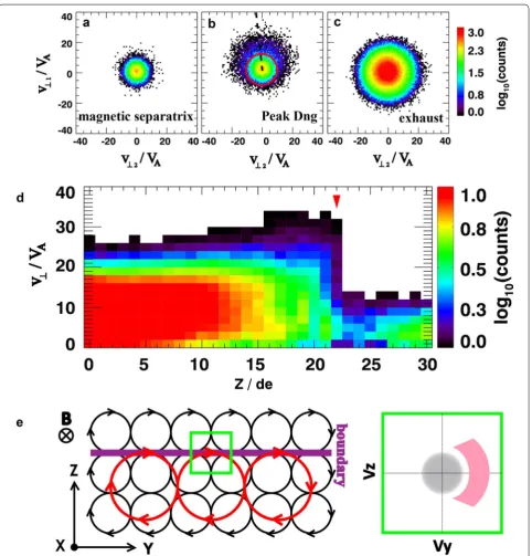
To analyze the nongyrotropic feature, Fig. 2a–c shows the plots of the eVDFs at x = 902de. The locations to get
the eVDFs are marked in Fig. 1a, b by small white rec-tangles. The eVDFs are organized in v⊥2 − v⊥1 space, the
plane perpendicular to the magnetic field, where v⊥1 is in
the direction of E × B, and v⊥2 the direction of B × v⊥1.
The eVDFs calculated at the magnetic separatrix are gyrotropic (see Fig. 2a), and the maximum energy is small compared with the eVDFs in the enhanced Dng region
(Fig. 2b) and the exhaust region (Fig. 2c, at exhaust side of the enhanced Dng region). The eVDF at the enhanced Dng region (Fig. 2b) contains a gyrotropic cold core
(marked by the red circle) similar to that at the magnetic separatrix (Fig. 2a) and a nongyrotropic population with larger perpendicular velocities. To illustrate the changes in the perpendicular energy when crossing the separa-trix region, Fig. 2d shows the electron spectra within the pitch-angle of [80°, 100°] along the intercepts at x = 902
de (marked as the vertical white lines in Figs. 1a, b).
The spectrum displays that the maximum perpendicu-lar velocities drop sharply at the enhanced Dng region
(marked by red inverted triangles in Fig. 2d). This dem-onstrates that the enhanced Dng region marks the
bound-aries of the heated/accelerated outcoming electrons, i.e., the electron separatrix (the inflow electrons are accelerated/heated parallel but not perpendicular to the
magnetic field (see Chen et al. (2008, 2009) for evidence from PIC and space observations as well as explanations).
The drastic drop of perpendicular electron popula-tions across the electron separatrix implies a finite gyro-radius effect, as evidenced by the expected distribution in Fig. 2e. An electron gyrates around the field line with a gyroradius of rce=meV⊥/eB. Electrons with lower
energy and smaller gyroradii (black circles with arrows) exist on both sides of the electron separatrix/boundary (presented as thick purple line), while the accelerated electrons with larger gyroradii (red circles with arrows) exist only below the electron separatrix. Accumulat-ing the electrons in the green box stretched across the boundary, we obtain the nongyrotropic distribution func-tion as shown in the right panel of Fig. 2e. The gray pop-ulation centered at the origin consists of the low energy electrons, while the pink nongyrotropic population is composed of the accelerated electrons, gyro motions of which are mainly in the Y direction near the electron separatrix. The eVDFs shown in Figs. 2b are consistent with this picture. In Fig. 2b, the projections of the −Vy
axis are marked by dashed black lines (v⊥2 = −0.1v⊥1,).
The nongyrotropic population with velocities larger than ~10VA (see the red cycle in Fig. 2b) is approximately
sym-metric with respect to the −Vy axis, indicating that the
nongyrotropic populations are mainly moving in the −Y
direction.
To illustrate how the electron separatrix and the finite gyroradius effect impact the current system, we decom-posed the current density and bulk velocities in Fig. 3. The vertical solid line marks the Dng peak, while the two
vertical dashed lines mark the separatrix region. The parallel current density (black curve in Fig. 3a) is mainly carried by electrons (red in Fig. 3b) in the inflow side of
Dng peak. In the outflow side, the parallel ion velocity
(black curve in Fig. 3b) becomes significant, but is still overridden by electron. The perpendicular current den-sity is mainly in the y-direction (green curve in Fig. 3a). In the separatrix region, the electron (red in Fig. 3d) is the major current carrier, while ion (black in Fig. 3d) is the major carrier in the outflow region. In the separatrix region, E × B drift is the dominant except at the peak
Dng region, where Ve⊥,y sharply is enhanced to exceed VE × B,y. On the other hand, the bulk velocity of the
cold-core components of the eVDF in Fig. 2b agrees well with the local E × B drift velocities (not shown). Therefore, the nongyrotropic electrons with high perpendicular velocities are the contributors that enable Vey to exceed
the E × B drift velocity. From the viewpoint of fluid, the enhanced Ve⊥,y is contributed by the diamagnetic
drift. Figure 3f shows the electron diamagnetic drift
of ~1de) and δVe⊥,y = Ve⊥,y − VE × B,y (blue curve). It
shows clearly that the diamagnetic drift has a signifi-cant effect on the electron separatrix (see, green curve in Fig. 3f). Figure 3e shows that the inflow ion (black) can cross the separatrix region transversely with the speed overriding E × B drift speed, indicating that the ion is not frozen-in and can be accelerated by the Hall field Ez, consistent with previous theories. The
perpen-dicular electron velocity has no significant component in the z-direction (red in Fig. 3e). Ve⊥,x (red in Fig. 3c) is
slightly greater than VE × B,y, which is also caused by the
diamagnetic drift (black in Fig. 3f).
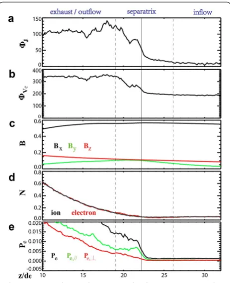
The current flow changes direction from along the field line to perpendicular to the field line when cross-ing the separatrix region from inflow to exhaust region. The changing of the current flow is mainly caused by the changing of the electron flow. Figure 4 shows the orien-tations of the current flow and the electron velocity and other physical parameters when crossing the separatrix. The azimuthal angles (in degree) in Fig. 4a, b (the angle between the +x axis and the velocity vector projected in the xy-plane, calculated in the clockwise orientation) clearly show the sudden changes in of the current and electron flows in the xy-plane, respectively, whereas, there are no obvious jumps in the magnetic field (Fig. 4c) and the number densities (Fig. 4d). The total electron pressure is quickly enhanced at the peak Dng region (black
in Fig. 4e), which is mainly contributed by the parallel electron pressure (green in Fig. 4e). The perpendicular electron pressure (red in Fig. 4e) is increased gradually. The quick enhancement of the parallel electron pressure
Fig. 3 The decompositions of the current and plasma flows. a The current density. The black curve presents the parallel current density, and blue for x-component of the perpendicular current, green for y-component of the perpendicular current, red for z-component of the perpendicular current. b The parallel bulk velocity for ions (black) and electrons (red). c–e x-, y-, z-components of the perpendicular bulk velocity for ions (black), electrons (red), and the E × B drift veloc-ity (green). f The electron diamagnetic drift velocity (black, green, and red for x-, y-, z-components respectively), and y-component of the difference between the perpendicular electron bulk velocity and the E × B drift, i.e., δVe⊥,y= Ve⊥,y− VE×B,y (green). The vertical solid
line marks the Dng peak, while the two vertical dashed lines mark the separatrix region where Ez is enhanced
indicates that the electrons can get more parallel heat-ing in the X-line and in the exhaust region, rather than in the inflow region. The absence of the jump in the per-pendicular electron pressure indicates that the diamag-netic drift and nongyrotropic feature are the secondary effects which cannot make any impact on the pressure balance. From this analysis, it can be suggested that the electron separatrix is a more important boundary than the magnetic separatrix, responsible for the changing of the orientation of current flow, the enhancements of the electron pressure tensor and of the out-of-plane electron velocity, all of which occur at the electron separatrix.
Conclusion
We have demonstrated that the out-of-plane current density has a peak near the electron separatrix, which implies that a thin current sheet formed in the separatrix region. The thin current sheet is mainly contributed by the electron diamagnetic drift, which is primarily caused by the finite gyroradius effect of outgoing accelerated electrons. Meanwhile, the finite gyroradius effect leads to nongyrotropic electron distributions and enhancement of Dng along the electron separatrix. The nongyrotropic
electrons contribute to the perpendicular velocity Vey,
and make Vey exceed the E × B drift velocity, enhancing
the Hall effect. The electron separatrix is marked by the enhanced out-of-plane electron velocity, electron non-gyrotropy, and divergence of electron pressure tensor, while it has no obvious effect on magnetic field and num-ber density. In addition, the current and electron flows changed their orientations at the electron separatrix. All these parameters can be the candidates to identify the electron separatrix and the separatrix region.
The time stage in this study is chosen to be near the reconnection peak. It is at an early stage in the whole reconnection evolution process, to get rid of turbulent-like features which arise at the later simulation stage. The original particles have not been expelled from the near
X-line region at the early stage, so the high plasma den-sity leads to a peak current denden-sity at the neutral center. However, the density decreased at later simulation stage when the dense plasma is expelled out by the reconnec-tion outflow. Then, the current density at the neutral center is reduced to less than that on separatrix region (not shown). That is to say the thin current layer studied in this paper can evolve into the bifurcated current sheet which has been observed in the magnetotail (Runov et al.
2003, 2006).
The thin current sheet and the associated finite gyrora-dius effect in the separatrix region discussed in this paper are different from those in the previous investigations of EDR on magnetopause (e.g., Hesse et al. 2014; Burch et al. 2016; Shay et al. 2016). In EDR on magnetopause,
the electrons are accelerated by the in-plane electric field during their meandering motions around the neutral line, in turn leading to the enhanced electron nongyrot-ropy and forming the crescent-shaped electron distribu-tion on the magnetosphere side of the EDR (Shay et al.
2016). In contrast, in the separatrix region, the magnetic fields are not reversed in the thin current sheet, and the accelerated electrons make cyclotron motions rather the meandering motions. In addition, the accelerated elec-trons had already been accelerated before arriving at the separatrix region. The boundary for the accelerated elec-trons in separatrix region is maintained by the magnetic reconnection process. In other words, it is the recon-nection process that generated the electron boundary to form the bifurcated thin current sheet in the separatrix region apart from the neutral line. Hence, the bifurcated current sheets can be a signature of active reconnection region, similar to the hypothesis proposed by Thomp-son et al. (2006). The phenomena discussed here could be independent of the background plasma environment, so we can suggest that the thin current sheet seen on the separatrix region could also be seen in the reconnection region on magnetopause. Furthermore, the findings from this study would also be helpful to diagnose the recon-nection region in the magnetotail.
Abbreviations
PIC: Particle-in-cell; EDR: electron diffusion region; eVDFs: electron velocity distribution functions.
Authors’ contributions
RG analyzed the data and drafted the paper. Prof. ZP and YW helped to discuss and organize the details of the paper. All authors read and approved the final manuscript.
Author details
1 Key Laboratory of Earth and Planetary Physics, Institute of Geology and Geo-physics, Chinese Academy of Sciences, Beijing 100029, China. 2 School of Earth and Space Sciences, Peking University, Beijing, China.
Acknowledgements
Ruilong Guo was supported by the China Scholarship Council for 1-year study at University of New Hampshire. Ruilong Guo thanks William Daughton and Li-Jen Chen for providing the simulation data, and thanks Li-Jen Chen, Shan Wang, Jason Shuster, Guanlai Li, and Roy Tobert for their help and fruitful discussion when analyzing the simulation data when studying in UNH.
Competing interests
The authors declare that they have no competing interests.
Availability of data and materials
The simulation data are provided by William Daughton and Li-Jen Chen when Ruilong Guo studying in University of New Hampshire. The simulation data are available upon request from the authors.
Consent for publication Not applicable.
Funding
The work was supported by the National Science Foundation of China (41525016, 41474155, 41661164034). Y. Wei was supported by Thousand Young Talents Program of China.
Publisher’s Note
Springer Nature remains neutral with regard to jurisdictional claims in pub-lished maps and institutional affiliations.
Received: 31 December 2016 Accepted: 29 August 2017
References
Aunai N et al (2013) Electron nongyrotropy in the context of collisionless mag-netic reconnection. Phys Plasmas 20:092903. doi:10.1063/1.4820953 Burch JL, Phan TD (2016) Magnetic reconnection at the dayside
magneto-pause: advances with MMS. Geophys Res Lett 43(16):8327–8338. doi:10.1 002/2016GL069787
Burch JL et al (2016) Electron-scale measurements of magnetic reconnection in space. Science. doi:10.1126/science.aaf2939
Cattell C et al (2005) Cluster observations of electron holes in association with magnetotail reconnection and comparison to simulations. J Geophys Res 110:A01211. doi:10.1029/2004JA010519
Chen LJ et al (2008) Evidence of an extended electron current sheet and its neighboring magnetic island during magnetotail reconnection. J Geo-phys Res 113:A12213. doi:10.1029/2008JA013385
Chen LJ et al (2009) Multispacecraft observations of the electron current sheet, neighboring magnetic islands, and electron acceleration during magne-totail reconnection. Phys Plasmas 16:056501. doi:10.1063/1.3112744 Chen LJ, Hesse M, Wang S, Bessho N, Daughton W (2016) Electron energization
and structure of the diffusion region during asymmetric reconnection. Geophys Res Lett 43(6):2405–2412. doi:10.1002/2016GL068243 Daughton W et al (2006) Fully kinetic simulations of undriven magnetic
reconnection with open boundary conditions. Phys Plasmas 13:072101. doi:10.1063/1.2218817
Daughton W et al (2009) Influence of Coulomb collisions on the structure of reconnection layers. Phys Plasmas 16:072117. doi:10.1063/1.3191718 Drake JF et al (2003) Formation of electron holes and particle energization
during magnetic reconnection. Science 299:873–877
Drake JF, Shay MA, Swisdak M (2008) The Hall fields and fast magnetic recon-nection. Phys Plasmas 15:042306. doi:10.1063/1.2901194
Egedal J, Fox W, Katz N, Porkolab M, Øieroset M, Lin RP, Daughton W, Drake JF (2008) Evidence and theory for trapped electrons in guide field magneto-tail reconnection. J Geophys Res 113:A12207. doi:10.1029/2008JA013520 Egedal J, Lê A, Katz N, Chen LJ, Lefebvre B, Daughton W, Fazakerley A (2010)
Cluster observations of bidirectional beams caused by electron trapping during antiparallel reconnection. J Geophys Res 115:A03214. doi:10.1029 /2009JA014650
Egedal J, Daughton W, Lê A (2012) Large-scale electron acceleration by paral-lel electric fields during magnetic reconnection. Nat Phys 8:321–324. doi:10.1038/NPHYS2249
Farrell WM et al (2002) The dominance of electron plasma waves near a reconnection X-line region. Geophys Res Lett 29:1902. doi:10.1029/200 2GL014662
Fujimoto K (2006) Time evolution of the electron diffusion region and the reconnection rate in fully kinetic and large system. Phys Plasmas 13:072904. doi:10.1063/1.2220534
Fujimoto K (2014) Wave activities in separatrix regions of magnetic reconnec-tion. Geophys Res Lett 41:2721–2728. doi:10.1002/2014GL059893 Hesse M, Aunai N, Sibeck D, Birn J (2014) On the electron diffusion region in
planar, asymmetric, systems. Geophys Res Lett 41:8673–8680. doi:10.100 2/2014GL061586
Hesse M, Liu YH, Chen LJ, Bessho N, Kuznetsova M, Birn J, Burch JL (2016) On the electron diffusion region in asymmetric reconnection with a guide magnetic field. Geophys Res Lett 43(6):2359–2364. doi:10.1002/201 6GL068373
Hwang KJ, Goldstein ML, Wendel DE, Fazakerley AN, Gurgiolo C (2013) Cluster observations near reconnection X lines in Earth’s magnetotail current sheet. J Geophys Res Space Phys 118:4199–4209. doi:10.1002/jgra.50403 Hwang K-J et al (2016) The substructure of a flux transfer event observed by
the MMS spacecraft. Geophys Res Lett 43:9434–9443. doi:10.1002/201 6GL070934
Khotyaintsev YV et al (2006) Formation of inner structure of a recon-nection separatrix region. Phys Rev Lett 97:205003. doi:10.1103/ PhysRevLett.97.205003
Lindstedt T et al (2009) Separatrix regions of magnetic reconnection at the magnetopause. Ann Geophys 27:4039–4056
Nakamura T, Nakamura R, Haseagwa H (2016) Spatial dimensions of the electron diffusion region in anti-parallel magnetic reconnection. Ann Geophys 34:357–367. doi:10.5194/angeo-34-357-2016
Norgren C et al (2016) Finite gyroradius effects in the electron outflow of asymmetric magnetic reconnection. Geophys Res Lett 43:6724–6733. doi :10.1002/2016GL069205
Phan TD et al (2016) MMS observations of electron-scale filamentary currents in the reconnection exhaust and near the X line. Geophys Res Lett 43:6060–6069. doi:10.1002/2016GL069212
Retinò A et al (2006) Structure of the separatrix region close to a magnetic reconnection X-line: cluster observations. Geophys Res Lett 33:L06101. doi:10.1029/2005GL024650
Runov A et al (2003) Current sheet structure near magnetic X-line observed by cluster. Geophys Res Lett 30(11):1579. doi:10.1029/2002GL016730 Runov A et al (2006) Local structure of the magnetotail current sheet: 2001
Cluster observations. Ann Geophys 24:247–262
Scudder J, Daughton W (2008) ‘‘Illuminating’’ electron diffusion regions of col-lisionless magnetic reconnection using electron agyrotropy. J Geophys Res 113:A06222. doi:10.1029/2008JA013035
Shay MA, Phan TD, Haggerty CC, Fujimoto M, Drake JF, Malakit K, Cassak PA, Swisdak M (2016) Kinetic signatures of the region surrounding the X line in asymmetric (magnetopause) reconnection. Geophys Res Lett 43:4145–4154. doi:10.1002/2016GL069034
Shuster JR et al (2015) Spatiotemporal evolution of electron characteristics in the electron diffusion region of magnetic reconnection: Implications for acceleration and heating. Geophys Res Lett. doi:10.1002/2015GL063601 Swisdak M (2016) Quantifying gyrotropy in magnetic reconnection. Geophys
Res Lett 43:43–49. doi:10.1002/2015GL066980
Thompson SM, Kivelson MG, El-Alaoui M, Balogh A, Reme H, Reme LM (2006) Bifurcated current sheets: statistics from Cluster magnetometer measure-ments. J Geophys Res 111:A03212. doi:10.1029/2005JA011009 Torbert RB et al (2016) Estimates of terms in Ohm’s law during an encounter
with an electron diffusion region. Geophys Res Lett 43:5918–5925. doi:10 .1002/2016GL069553
Viberg H et al (2013) Mapping HF waves in the reconnection diffusion region. Geophys Res Lett 40:1032–1037. doi:10.1002/grl.50227
Wang S, Chen LJ, Bessho N, Kistler LM, Shuster JR, Guo R (2016) Electron heat-ing in the exhaust of magnetic reconnection with negligible guide field. J Geophys Res Space Phys 121:2104–2130. doi:10.1002/2015JA021892 Yao Z et al (2013) Current structures associated with dipolarization fronts. J
Geophys Res Space Phys 118:6980–6985. doi:10.1002/2013JA019290 Yao Z et al (2016) Substructures within a dipolarization front revealed by
high-temporal resolution Cluster observations. J Geophys Res Space Phys 121:5185–5202. doi:10.1002/2015JA022238