Dexterous Workspace Shape and Size
Optimization of Tricept Parallel Manipulator
Mir Amin Hosseini
a, Hamid-Reza Mohmmadi Daniali
ba-PhD student of Mechanical Engineering Department, Babol University of Technology, Babol, Iran. E-mail: [email protected]. b-Corresponding Author, Associate Prof. Department of Mechanical Engineering, Babol University of Technology, Iran, 47148-71167. E-mail: [email protected]. Tel: +981113234205, Fax: +981113212268.
A R T I C L E I N F O A B S T R A C T
Keywords:
Tricept Cuboid Shape Dexterous Workspace Complex Degrees of Freedom Parallel Manipulators Genetic Algorithm Method
This work intends to deal with the optimal kinematic synthesis problem of Tricept parallel manipulator. Observing that cuboid workspaces are desirable for most machines, we use the concept of effective inscribed cuboid workspace, which reflects requirements on the workspace shape, volume and quality, simultaneously. The effectiveness of a workspace is characterized by the dexterity of the manipulator all over its workspace. Tricept has a complex degree of freedom, i.e. both rotational and translational DoF, therefore its performance indices depend on the singular values of the dimensional in-homogeneous Jacobian. Here, we divide the Jacobian entries by units of length, thereby producing a new Jacobian that is dimensionally homogeneous. By multiplying the associated entries of the twist array to the same length, we made this array homogeneous as well. This implies some sort of tradeoff between position and orientation components of the twist array. An optimal design problem, including constraints on actuated and passive joint limits, is then formulated. This problem is a constrained nonlinear optimization problem. Therefore, Genetic Algorithm toolbox of Matlab is adopted to solve the problem.
1. Introduction
Parallel manipulators have received extensive attention over the last two decades for their potential superior properties, such as low inertia, high stiffness, high precision and high load carrying capacity [1-3]. However, they suffer from smaller workspace relative to their serial counterparts. Choosing a set of geometric parameters so as to achieve optimal performance is of vital significance in robotics research [4-6]. Among all kinematic measures, workspace is the most important index in the design of a parallel manipulator. A parallel manipulator designed only for maximum workspace volume may not however be a good design in practice. It is possible that the manipulator with maximum workspace has undesirable kinematic characteristics such as poor dexterity and irregular shape [7]. In order to avoid undesirable effects of workspace volume maximization, researchers introduced other
performance indices into the optimal design problem [8-10]. Li and Xu [8] optimized Delta as a translational parallel manipulator to have a good conditioning index and stiffness. In [10] 3-PRS optimization to achieve maximum dexterous workspace (MDW) was performed. In [7] MDW of Tricept manipulator was addressed, using Genetic Algorithm (GA) method, while the shape of the workspace is much more important in some applications of robots. Liu and Li addressed the optimal effective regular workspace of parallel manipulators [11].
the manipulator subject to the constraints on LCI and MSV. In practice, although a cuboid workspace is desirable, parallel manipulators often have irregular-shaped workspaces due to their complex kinematic structures. Tricept does not exempt from this rule. A design solely for maximal workspace may not have the maximal cuboid workspace. Therefore, the optimal design problem is formulated to maximize the volume of inscribed cuboid in the workspace subject to dexterity constraints; namely, LCI and MSV. Furthermore, a design purely for maximal inscribed cuboid (MIC) workspace may also lead to smaller workspace volume. Therefore, we use the concept of effective inscribed cuboid workspace, which reflects requirements on the workspace shape, volume and quality, simultaneously. That is, we employ a linear combination of measures on the volume of workspace and MIC in the objective function, while keeping the above mentioned quality constraints.
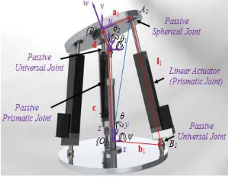
2. Tricept Mechanism
One of the most famous parallel manipulators with machine tool application is Tricept family which has both rotational and translational degrees-of-freedom (dof) [12]. A comparison study is performed by Pond [13] between Tricept and some other parallel robots with the same number of degrees of freedom, such as, 3-PRS and 3-RPS by considering their condition numbers and maximum and minimum singular values. The manipulator has three actuated limbs which connect the base to the moving platform. Each of these limbs consists of a spherical-prismatic-spherical (SPS) kinematic chain, where only the prismatic joint is actuated. Alternatively, one of the spherical joints can be replaced by a universal joint. Moreover, a passive prismatic-universal (PU) limb connects the center of the moving platform to the base. We attach frames {P (uvw)} and {O (xyz)} to the moving and base platforms, respectively. When the moving platform is parallel to the base, the two revolute axes of the universal joints of the center passive leg are parallel with the base frame's x and y axes, respectively.
Siciliano [14] studied the kinematics and manipulability of Tricept. Pond and Corretero formulated its square dimensionally homogeneous Jacobian matrices based on three independent coordinates of three nodes of the moving platform [15]. Architectural optimization of Tricept was studied by Zhang and Gosselin [16]. They used GA to optimize the stiffness and end-effector (EE) accuracy.
2.1. Velocity Analysis
The loop closure equation for the ith leg can be written
as:
(1) ( i ) bi bi li li
R
c a d n n
where c and d are the vectors from O to C and C to P, respectively. While R is rotation matrix carrying frame
{P} into an orientation coincident with that of frame {O}; ai is the position vector from P to Ai in frame {P};
bi is the position vector of point Bi in the global frame.
Moreover, nbi and nli are the unit vectors showing the
directions of vectors bi and li, respectively.
Figure 1: Tricept structure and geometric model.
Taking the first time derivative of Eq.1 yields:
( ( ))
p i li li l li li
R
c ω a d n ω n (2)
where ωp and ωl are the angular velocity vectors of the
EE and limb, respectively. Pre-multiplying both sides of Eq.2 by nliT, upon simplifications and written them for
for i=1...3, yields:
(3) 1
J x q
where
x =
c
T is the three dimensional twist vector;q =
l
1l
2l
3
T is the three dimensional actuator velocity vector and J-1 is theinverse Jacobian matrix, namely;
1 1 l1 1 l1
1
2 2 l2 2 l2
3 3 l3 3 l3
( ( ) ) ( ( ) )
( ( ) ) ( ( ) )
( ( ) ) ( ( ) )
l z x y
l z x y
l z x y
n n n
R R
J R R
R R
a d n a d n
a d n a d n
a d n a d n
(4) 3. Workspace Analysis
In this section, we study the workspace of a Tricept manipulator numerically.
3.1. Algorithm
In order to generate the workspace of a Tricept parallel manipulator, we divide the three dimensional ψ-θ-Z workspace of the moving platform into a series of sub-workspaces that are parallel to ψ-θ plane. Then a numerical searching method, was introduced in [17, 18], is adopted here to determine the boundary of the sub-workspaces. Finally, the volume of workspace is calculated quantitatively.
3.2. Geometric Constraints
3.3. Design Constraints
In order to guarantee the workspace to be effective, constraints on the dexterity indices are introduced to characterize quality of the workspace.
Figure 2: Geometric constraints of Tricept robot. Table 1: Geometric constraints of the Tricept manipulator.
Condition number is quite often used as an index to describe the dexterity of a robot and the distance of a pose from a singularity. The condition number also measures the magnitude of the relative error of the wrench introduced by the relative error in joint torques and reflects the sensitivity of the wrench due to joint torque error. Similarly, the use of minimum allowable singular value restricts the workspace to poses where the manipulator moves at a minimum allowable speed. Here, we optimized Tricept for dexterity measures, namely; the inverse of condition number as a LCI and the MSV.
In engineering applications, we often attach a great importance to study the dexterous workspace (DW) of a manipulator rather than the reachable workspace. Moreover, kinetostatic performance or dexterity measures how well the system behaves with regard to force and motion transmission. Several dexterity criteria could be taken into account; such as service angle, manipulability, MSV, maximum singular values and condition number [19]. Condition numbers and MSV of the Jacobian matrices are known as a kinetostatic performance index of parallel manipulators [20, 21]. Indeed, in order to determine the condition number and MSV of the Jacobian matrices, we must order their singular values from largest to smallest. However, in the presence of positioning and orienting tasks, three of these singular values, namely, those associated with positioning, are dimensionless; while those associated with orientation have units of length, thereby making impossible such an ordering.
Ranjbaran and Angeles [22] resolved this inconsistency by defining a characteristic length, by which they divided the Jacobian entries that have units of length,
thereby producing a new Jacobian that is dimensionally homogenous. Ma and Angele [20] introduced another ratio called natural length and used it for design optimization. Chablat et al., used characteristic length to determine the design parameters of a planar parallel mechanism with PRR chains to have an isotropic condition [23]. Gosselin [24] introduced a method for formulating dimensionally homogenous Jacobian matrix for a planar mechanism with one rotational and two translational dof. The Jacobian matrix relates the actuator velocities to the velocities of the x and y coordinates of two points on the EE platform. Kim and Ryu [25] furthered this work by using the velocities of three points on the EE platform to develop a dimensionally homogenous Jacobian matrix. Pond and Corretero [15] further developed this method by using three independent coordinates of three points on EE platform. Moreover, Angeles [26] introduced engineering characteristic length for a rigid body transformation matrix to make it homogenous. Mansouri [27] used power transition concept to make the Jacobian homogeneous. Hosseini et. al. [7] resolved the inconsistency by defining a weighting factor, by which they divided the Jacobian entries that have units of length, thereby producing a new Jacobian that is dimensionally, homogeneous. Moreover, one might choose different weighting factors for different coordinates of twist array and the associated columns of the Jacobian matrix, even those with the same units. Dividing the second and the third columns of the Jacobian matrix of Eq. 3 by a length and multiply the second and the third coordinates of the twist vector to the same length leads to the following dimensionally homogeneous relation: 1 l1 1 l1 1 1 2 l2 2 l2 2 2 3 3 l3 3 l3 3 ( ( ) ) ( ( ) ) ( ( ) ) ( ( ) ) ( ( ) ) ( ( ) ) y x l z y x l z y x l z n
l l c l
n l l
l l l l n l l R R R R R R
a d n a d n
a d n a d n
a d n a d n
(5)
Physically, this implies some sort of tradeoff between position and orientation components of twist array. This weighting factor should be constant throughout the workspace. The designer should choose the weighting factor based on the application of the mechanism. For example, in a milling operation as depicted in Figure 3, the radius of end-milling cutter is the length that relates the tangential cutting force to the torque and should be chosen as the weighting factor by the designer. It is noteworthy that the same factor relates angular velocity to linear velocity. Moreover, one might compare one unit of the linear velocity with m×l units of angular velocity around x axis and n×l units of angular velocity around y axis. So, we can assign different weighting factors to the different coordinates of the twist vector ra
(mm) rb (mm) d (mm) ζ (deg) Actuator Length
(mm)
Figure 3: Weighting factor in a milling operation.
4. GENETIC ALGORITHM OPTIMIZATION
One of the drawbacks of parallel manipulators is their limited workspace. It is more limited in the presence of constraints such as dexterity, isotropy and joints limits. Clearly the optimal design problem is a constrained nonlinear optimization problem. Here, we resort to a direct search method; namely, GA which was widely studied as a global optimization technique [28-31]. The algorithm is robust, i.e., it normally works regardless of irregularities of the objective function.
4.1. Setup of the GA Optimization
● Design Variables
There are three parameters in the optimization process which define the manipulator architecture. They are the moving and base platform radiuses (ra
and rb), and the upper part of middle link length (d)
whit their boundaries as given in Table 1.
● GA Optimization Setup
In order to apply the GA for optimization, six fundamental issues are required to be determined, i.e., the chromosome representation, selection function, genetic operators, population size, termination criteria, and evaluation function [30]. For the current optimization problem, the objective functions are chosen as the evaluation functions. Moreover, actuators length, joints limitations are the geometric constraints, while lower bound of MSV and LCI are the design constraints.
5. Case Study
5.1. Maximal Workspace Volume with Geometric Constraints
Here, the workspace is parameterized using three design parameters; namely, the moving and base platform radiuses (ra and rb) and the upper part of
passive link length (d), all summarized in the vector form as λ=[ra rb d]T.
Then, using GA method, the workspace is optimized subjects to some geometric constraints as given in table 1. Therefore, our optimization problem yields to:
(6) V*=Max(V(d, r
a, rb))
Subject to:
200< ra < 300, 300 < rb < 500, 20 <d <200, 2-
400<Actuator Length(l)<750, -60< ζi<60 deg
in which V is a function to calculate the workspace volume. Solving this optimization problem by GA leads to the data given in Table 2, in which the maximal workspace is 858.9751 mm.Rad2.
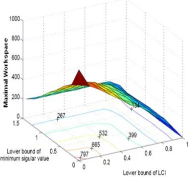
5.2. Constraints Evaluation
In the followings, we evaluate non-geometric constraints; namely, MSV and the inverse of condition number of the Jacobian as LCI for different elevation ranges of the foregoing manipulator. The workspace volume versus lower bound of LCI and MSV is depicted in figure 4. As the minimum permissible limit on singular values is increased, the workspace continues to be reduced. Moreover, as the minimum permissible limit on LCI is increased, the workspace continues to be reduced, as well.
Table 2: Maximal workspace volume with geometric constraints. ra
(mm) rb
(mm) d (mm) V*
(mm.Rad2)
No. of Iteration
200 300 20 858.9751 51
Considering any minimum permissible limit on singular values leads to the workspace with lower bound for EE velocities; while considering the minimum permissible limit on LCI leads to the manipulator as close as to isotropic conditions. For the workspace of the manipulator, depicted in Table 2, considering the minimum permissible limit on LCI to be greater than or equal to 0.6 and MSV to be greater than or equal to 1, yields to the workspace of Figure 5, with the volume of 267.4887Rad2.mm. This volume is 68.86% smaller than
the original one, without considering these constraints.
Figure 5: Sub-workspace of the maximal workspace by limiting MSV and LCI.
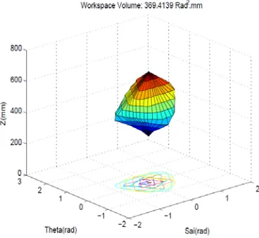
5.3. Dexterous and High Velocity Workspace Volume
In the followings, the workspace volume of the Tricept is optimized by constraining the MSV and LCI of the Jacobian matrix to be within a desired range along with the geometric constraints of Table 1. Therefore, the optimization problem can be re-written as:
(7) W*=Max(V(c, r
a, rb))
Subject to:
1-LCI >= 0.6, σmin>=1
2-200< ra < 300, 300 < rb < 500, 20 <d
<200, 400<Actuator Length(l)<750, -60<ζi<60deg
Solving this problem by GA leads to the data given in Table 2, in which the maximal workspace is 369.4139 mm.Rad2, which is 38.1% more than that
volume of Figure 5. This workspace is illustrated in Figure 6.
Table 3: Optimization results for design constrained workspace. ra
(mm) rb
(mm)
d
(mm)
W*
(mm.Rad2)
No. of
Iteration
203.052 454.518
127.293 369.4139
52
Figure 6: Maximal dexterous workspace (DW).
5.4. Effective Inscribed Cuboid Workspace As it is depicted in the Figure 6, MDW might lead to an irregular shape. Therefore, it is essential to reach a maximal workspace as close as to a regular shape such as a cuboid or a cylinder. In the following, using GA method, we will find the MIC. It is noteworthy that we will give different weights to the rotational dof than the translational one.
5.4.1. Maximal Inscribed Cuboid
Here, we use an iterative search algorithm to find the MIC in the workspace. This method includes the following steps:
Step1. Cuboid center determination: Due to symmetry, the coordinates of the cuboid center, without loosing of generality, is assumed as ψ=0, θ=0 and Z equal to the average altitude of the EE in the workspace.
Step2. A complete rotation of a cuboid around Z axis: For each step, the lengths of the cuboid will be increased incrementally. The largest inscribed cuboid in each step of rotation will be registered.
Step3. The MIC: The largest registered cuboid and its related rotation can define the MIC in the DW.
Figure 7 illustrates the MIC in the DW, in which we have the volume of cuboid equal to 88.3362mm.Rad2,
and its aspect ratio equal to 208.687. However, the related DW is 307.2612 mm.Rad2; some 17% smaller
than the MDW of Figure 6. These design parameters is summarized in Table 4.
Table 4: MIC and the design parameters. ra rb d
A.R.
MICVolume
(mm.Rad2
) DWVolume
(mm.Rad2
) No. of Iteration
202.041 321.742 39.542
208.687
a. MIC in the related DW
b.DW includes the MIC Figure 7: MIC in DW with A.R. 208.687
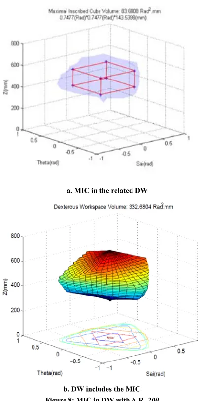
5.4.2. Maximal Inscribed Cuboid with a Desired Aspect Ratio
Here, using the same algorithm, we find MIC in the DW with a desired aspect ratio equal to 200. Moreover, the MIC in the DW leads to the data of Table 5 which is illustrated in Figure 8. As it is expected, the volume is further decreased to 83.601 mm.Rad2, which only fills
25.13% of the DW volume.
5.5. Effective Inscribed Cuboid Workspace Here, we employ a linear combination of measures on the volume of workspace and MIC in the objective function, while keeping the above mentioned quality constraints, i.e., the objective function is defined as:
max (1 ) c
max max
V W
V
w v
(8)
where, wmax and vmax are the largest workspace and the
volume of the MIC, respectively. Also, W and Vcare the
DW and its related inscribed cube volume, respectively.
Moreover, κ is the weight factor for the volume of cuboid and the workspace volume.
Solving this problem for κ =0.2 by GA leads to the data given in Table 6 and the workspace is illustrated in Figure 9. As it is seen, we can increase the volume of the inscribed cuboid with the cost of robot workspace volume.
a. MIC in the related DW
b. DW includes the MIC Figure 8: MIC in DW with A.R. 200
Table 5: MIC and the design parameters with A.R. 200
ra
rb
d
Cube Volume
(mm.Rad2)
No. of
Iteration
200 453.527 90.401
83.6008 51
reduced, as well.
a. MIC in the related DW
b. Dexterous workspace
Figure 9: Workspace and its related MIC for k=200.
Table 6: DW and its related MIC and design parameters.
ra
rb
d
Obj. F. DW Vol. MIC Vol. A.R.
No. of Iteration
202.193 324.221 80.311 0.9532 339.8771 82.6599 172.682 75
Figure 10: DW volume versus design constraints.
6.Conclusion
In this paper the workspace optimization of Tricept was performed. This parallel manipulator has a complex degree of freedom, therefore has leaded to dimensional in-homogeneous Jacobian matrices. Here, we divided
some entries of the Jacobian by units of length, thereby producing a new Jacobians that is dimensionally homogeneous. By multiplying the associated entries of the twist array to the same factor, we made this
Figure 11: MIC volume versus design constraints.
array homogeneous as well. For the platform, the workspace was parameterized using some design parameters. Then, using GA method, the workspace was optimized subjects to some geometric constraints. Moreover, LCI and MSV were calculated for the workspace of the manipulator. Finally, we used the concept of effective inscribed cuboid workspace, which reflected requirements on the workspace shape, volume and quality, simultaneously. It was shown that by introducing the LCI and MSV as the quality measures throughout the workspace, the performance of the manipulator was improved at the cost of workspace reduction.
References:
[1] T. Huang, C.M. Gosselin, D.J. Whitehouse and D.G. Chetwynd, Analytical approach for optimal design of a type of spherical parallel manipulator using dexterous performance indices, Proceedings of the Institution of Mechanical Engineers, Part C: Journal of Mechanical Engineering Science 217(4) 447-456 (2003).
[2] V. Parenti-Castelli, R. Di Gregorio and F. Bubani, Workspace and Optimal Design of a Pure Translation Parallel Manipulator, Meccanica 35, 203–214 (2000). [3] X-J. Liu, J. Wang and H. Zheng, Workspace atlases for the
computer-aided design of the Delta robot, Proceedings of the I. MECH. E. Part C: Journal of Mechanical Engineering Science, 217, 861-869 (2003).
[4] J-P. Merlet, Designing a parallel manipulator for a specific workspace, Int. J. Rob. Res., 16 (4) 545–556 (1997). [5] R. Boudreau and C.M. Gosselin, The synthesis of planar
parallel manipulators with a genetic algorithm, J. Mech. Des., 121 (4) 533–537 (1999).
[6] M.A. Laribi, L. Romdhane and S. Zeghloul, Analysis and dimensional synthesis of the DELTA robot for a prescribed workspace, Mechanism and Machine Theory, 42, 859–870 (2007).
(2011).
[8] Y. Li and Q. Xu, Optimal kinematic design for a general 3-PRS spatial parallel manipulator based on dexterity and workspace, The Eleventh International Conference on Machine Design and Production, Antalya, Turkey (2004).
[9] Q. Xu and Y. Li, Kinematic Analysis and Optimization of a New Compliant Parallel Micromanipulator, International Journal of Advanced Robotic Systems, 3 (4), 351-358 (2006).
[10] G. Pond and J.A. Carretero, Architecture optimization of three 3-PRS variants for parallel kinematic machining, Robotics and Computer-Integrated Manufacturing, 25(1) 64-72 (2009).
[11] Y. Lou, G. Liu and Z. Li, Randomized optimal design of parallel manipulators, IEEE Trans. On Automation Science and Engineering (2007).
[12] K.-E. Neumann, US patent 4,732,525, Mar. 22 (1988). [13] G. Pond, Dexterity and Workspace Characteristics of
Complex Degree of Freedom Parallel Manipulators, PhD Thesis, Department of Mechanical Engineering, University of New Brunswick (2006).
[14] B. Siciliano, The Tricept robot: Inverse kinematics, manipulability analysis and closed-loop direct kinematics algorithm, Robotica, 17(4) 437- 445 (1999). [15] G. Pond and J.A. Carretero, Quantitative dexterous
workspace comparison of parallel manipulators, Mechanism and Machine Theory, 42(10) 1388-1400 (2007).
[16] D. Zhang, C.M. Gosselin, Kinetostatic analysis and design optimization of the tricept machine tool family, Journal of Manufacturing Science and Engineering, 124(3) 725-733 (2002).
[17] Y. Li and Q. Xu, Kinematics and Stiffness Analysis for a General 3-PRS Spatial Parallel Mechanism, Proc. Of ROMANCY, Montreal, Canada (2004).
[18] J.A. Carretero, M.A. Nahon and R.P. Podhorodeski, Workspace analysis and optimization of a novel 3-DOF parallel manipulator, International Journal of Robotics and Automation, 15(4) 178-188 (2000).
[19] C.M. Gosselin and J. Angeles, A global performance index for the kinematic optimization of robotic manipulators, ASME Trans. J. Mech. Des., 113 (3) 220–226 (1991).
[20] O. Ma and J. Angeles, Optimum architecture design of platform manipulators, Proc. IEEE Int. Conf. Advanced Robotics (1991).
[21] R.E. Stamper, L-W. Tsai and G.C. Walsh, Optimization of a three DOF translational platform for well-conditioned workspace, 1997 IEEE Int. Conf. on Robotics and Automation, 4, 3250-3255 (1997).
[22] F. Ranjbaran, J. Angeles, M.A. Gonzalez-Palacios and R.V. Patel, The mechanical design of a seven-axes manipulator with kinematic isotropy, Journal of Intelligent and Robotic Systems, 14, 21-41 (1995). [23] D. Chablat, Ph. Wenger, S. Caro and J. Angeles, The
iso-conditioning loci of planar three dof parallel manipulators, Proceedings of DETC’2002, ASME Design Engineering Technical Conferences, Montreal, Quebec, Canada(2002).
[24] C.M. Gosselin, The optimum design of robotic manipulators using dexterity indices, Journal of Robotics and Autonomous Systems, 9 (4) 213–226 (1992). [25] S-G. Kim, J. Ryu, New dimensionally homogeneous
jacobian matrix formulation by three end-effector points for optimal design of parallel manipulators, IEEE Transactions on Robotics and Automation, 19 (4) 731–737(2003).
[26] J. Angeles, Is there a characteristic length of a rigid-body displacement?, Mechanism and Machine Theory, 41, 884–896(2006).
[27] I. Mansouri and M. Ouali, A new homogeneous manipulability measure of robot manipulators based on power concept, Journal of Mechatronics, 19, 927–944(2009).
[28] N. M. Rao, and K. M. Rao, Dimensional synthesis of a spatial 3-RPS parallel manipulator for a prescribed range of motion of spherical joints, Mechanism and Machine Theory, 44(2), 477-486(2009).
[29] Y. Li and Q. Xu, GA-Based Multi-Objective Optimal Design of a Planar 3-DOF Cable-Driven Parallel Manipulator, Proceedings of the 2006 IEEE International Conference on Robotics and Biomimetics, December 17 - 20, Kunming, China(2006).
[30] C. Houck, J. Joines and M. Kay, A genetic algorithm for function optimization: A matlab implementation, North Carolina State University, Raleigh, NC, Tech. Rep. NCSU-IE-TR-95-09 (1995).
[31] S. Kucuk, A Dexterity Comparison for 3-DOF Planar Parallel Manipulators with Two Kinematic Chains Using Genetic Algorithms, Int. J. of Mechatronics, 19(6) 868-877(2009).
Biography of Authors:
Mir Amin Hosseini is currently PhD student in the Department of Mechanical Engineering, from Babol University of Technology. He received his B.Sc. in Manufacturing Engineering from Tehran Polytechnic University and M.Sc. in Manufacturing Engineering from Tarbiat Modarres University. His research interests focus on parallel machine tools. `