University of New Orleans University of New Orleans
ScholarWorks@UNO
ScholarWorks@UNO
University of New Orleans Theses and
Dissertations Dissertations and Theses
12-15-2007
Disaster Response System
Disaster Response System
Shiquan Fu
University of New Orleans
Follow this and additional works at: https://scholarworks.uno.edu/td
Recommended Citation Recommended Citation
Fu, Shiquan, "Disaster Response System" (2007). University of New Orleans Theses and Dissertations. 616.
https://scholarworks.uno.edu/td/616
Disaster Response System
A Thesis
Submitted the the Graduate Faculty of the
University of New Orleans
in partial fulfillment of the
requirements for the degree of
Master of Science
in
Computer Science
By
Shiquan Fu
B.S. Peking University, 2003
December 2007
Table of Contents
Abstract...iii
Introduction...1
Background...2
Object-Relation Mapping...2
Model View Control...4
Geocoder...4
Geocoder Proxy Bean...6
Oracle Spatial...8
Components...8
Storing Spatial Data...9
Location Enabling...10
Query and Analysis...14
The Geometry Engine...14
The Index Engine...16
Disaster Response System ...20
System Requirements...20
Use-Cases...20
Design...21
Relational Database Design...21
Allocation Rule...23 Object-Relation Structure...26 Implementation...28 User Interface...28 MVC Implementation...37 Connection Pooling...37 Geocoder...42 Allocation Table...44 Controller Objects...46 Functionality Summary...47
Walk Through I...47
Walk Through II...51
Conclusion...54
Appendix A – Eclipse ...55
Introduction...55
History...55
Architecture...56
Web Tools Platform...57
Abstract
With integration of geospatial information system into a conventional information system a basic
disaster response information system is implemented. The result is a report on various useful
technologies and software engineering methodologies that could be utilized to implement a preliminary
system, which in turn clarifies many uncertainties and surprises that are typical of many such systems.
The foundations of my project include the Unified Process of software development, the relational data
models, the decision tree technique, class design principles such as the MVC pattern.
Introduction
The Hurricane Katrina disaster highlighted the need for geographic information, which is
critical to the strategic first response to disasters and to the mitigation after disasters. Many
failures in Katrina responses revealed that large-scale disaster mitigation is one of the most
complicated management tasks in government at all levels. Merely providing data will not
automatically and effectively support decision making. The lesson learned is that
communication facilities and robust information systems take on a crucial role and business
intelligence will be a necessary component.
The goals of my thesis project are to develop a simplified prototype of a basic disaster
response information system, and experiment the process of developing such a system that
contains many uncertainties and unknowns. The foundations of my project include the
Unified Process of software development, the relational data models, the decision tree
technique, class design principles such as the MVC pattern. A challenge in my
implementation is how to integrate geospatial information system into a conventional
information system. In doing so, I utilized two powerful tools: Oracle Spatial data
management capability and Geocoder.us Web services. Many graphical user interfaces were
developed in order to facilitate the requirement collection process.
While the mind set of this project was based on the painful experiences as a result of the
Hurricane Katrina disaster, the resulting prototype works for any disaster response situation. I
believe developing such system is a conceptually challenging and intellectually demanding
Background
In this section we explain the basic element of design employed in this project to obtain the
desired and final deliverable.
Object-Relation Mapping
Objects and relational databases structure data differently. For example many parts of
objects, such as collections and inheritance, are not available to relational databases. As the
business logic gets more complicated managing the correspondence between the two
structures gets even more complicated. As a result, for the purpose of this project a simple
mapping structure is between objects and relations are created. The mapping is as follows:
every entity and relation in the RDBMS design has a corresponding Java class with the same
return type and construct as the database implementation called the “Entity Class”. The
constructor for the Entity Class populates the values corresponding to a row in the database.
In addition there are getters and setters to simplify the design. “Entity Container Class” is
then the set of corresponding operations that are allowed for that class. Illustrations 1 and 2
Illustration 1: Class Diagram showing the basic Object-Relation mapping in DRS.
Model View Control
Model View Control (MVC) is a paradigm in which the system data (model) is decoupled
from the system user interface (view) by introducing an additional component called
controller. The reason is to employ separation of responsibilities in a software team to boost
productivity, usability and maintainability.
DRS uses Oracle Database and the corresponding object representation of data as the model,
while using Java Server Pages as the view and Java Servlets as the controller. The following
illustration depicts this architecture.
Geocoder
In this project geocoding is performed using a free service provided by Geocoder.us.
Geocoding is the process of estimating a latitude and longitude for a given address or
intersection. The Geocoder.us uses a PERL module that searches through a compresses 24
gigabyte of data collected by US Census Bureau. The compressed dataset is 750 megabyte
and is stored in BerkleyDB.
Illustration 3: MVC architecture in DRS
Model
View
Controller
HTML JSP CSS JavaScript
Oracle
Geocoder.us offers four different ways to access the web services: an XML-RPC interface, a
SOAP interface, a REST interface that returns an RDF/XML document, and a REST interface
that returns a plain text comma separated values result. The methods and return values are
equivalent across all three interfaces. For the purpose of this project a SOAP client is created
to communicate through the SOAP interface. A routine interaction between the objects is
depicted in the illustration 4:
Apache Axis's WSDL2Java tool is used to generate our SOAP client using the Geocoder.us
Web
Services Description Language. The command used is:
WSDL2Java tool generates the JAVA binding methods (outlined in the WSDL file) that can
invoke services offered by Geocoder.us using SOAP. java org.apache.axis.wsdl.WSDL2Java
-t -o src -Nhttp://rpc.geocoder.us/Geo/Coder/US/=samples.mapMashup http://geocoder.us/dist/eg/clients/GeoCoder.wsdl
Geocoder Proxy Bean
A proxy bean is created to invoke the Geocoder.us services by associating to the
Axis-generated SOAP client. A basic proxy bean is as following:
The class diagram as figures in illustration 5 summarizes the structure of such solution. public class GeoCoder {
public GeoCoder() { }
public GeocoderAddressResult[]
geocode(String location) throws IOException, ServiceException { GeoCode_BindingStub binding =
(GeoCode_BindingStub) new GeoCode_ServiceLocator().getGeoCode_Port();
// Time out after a minute binding.setTimeout(60000);
GeocoderAddressResult[] values = binding.geocode_address(location); return values;
Oracle Spatial
Oracle Spatial provides a SQL schema and a set of routines that facilitate storage, acquiring,
modifying a collection of spatial features in Oracle database. More specifically Oracle Spatial
includes:
• A schema that regulates the storage, syntax, and semantics of certain geometric data.
• A spatial indexing facility.
• Tools for performing geometric operations on data.
• Functions for utility and tuning operations.
• A graph topology of data and operations for nodes, edges and faces in a topology.
• A GeoRaster feature to store, index, query, analyze, and deliver GeoRaster data.
Components
• Data model: Oracle Spatial uses a SQL data type, SDO_GEOMETRY, to store spatial
data inside an Oracle database. Users may define tables containing columns of type
SDO_GEOMETRY to store the locations of customers, stores, restaurants, and so on,
or the locations and spatial extents of geographic entities such as roads, interstates,
parks, and land parcels.
• Location enabling: Users can add SDO_GEOMETRY columns to application tables.
In addition, users can populate the tables with SDO_GEOMETRY data using standard
Oracle utilities such as SQL*Loader, Import, and Export. Alternatively, users can
convert implicit spatial information, such as street addresses, into SDO_GEOMETRY
• Spatial query and analysis: Users can query and manipulate the SDO_GEOMETRY
data using the query and analysis component, comprising the Index and Geometry
Engines.
• Advanced Spatial Engine: This component comprises several components that cater to
sophisticated spatial applications, such as GIS and bioinformatics. This includes, for
example, the GeoRaster component that allows storage of spatial objects using images
(groups of pixels) rather than points, lines, and vertices.
• Visualization: The Application Server components of Oracle’s spatial technology
include the means to visualize spatial data via the MapViewer tool. MapViewer
renders the spatial data that is stored in SDO_GEOMETRY columns of Oracle tables
as displayable maps.
Note: The core subset of this functionality (known as the Locator component) is included for
free in all editions of the database (essentially, the SDO_GEOMETRY data type and the
Index Engine). The rest of the components, along with the data type and the Index Engine,
are packaged in a priced option of the Enterprise Edition of the database (known as the
Spatial option).We discuss this in more detail herein.
Storing Spatial Data
Generally spatial information is specified using two components: a location with respect to
some origin and a geometric shape.
• Location specifies where the data is located with respect to a two-, three-, or four
dimensional coordinate space. For instance, the center of San Francisco is located at
coordinates (.122.436, .37.719) in the two-dimensional “latitude, longitude” space.
examples of possible shapes. For instance, the center of San Francisco is located at
coordinates (.122.436,
• .37.719) in the two-dimensional “latitude, longitude” space and is a point shape. Note
that point specifies both a location and a default shape. Alternately, shape could
specify a line or a polygon connecting multiple points (specified by their locations).
For instance, the city boundary of San Francisco could be a polygon connecting
multiple points.
In some applications, the shapes could be more complex and could have multiple polygons,
and/or polygons containing holes. For instance, the state boundaries for Texas and California
include multiple polygons and some with islands. In general, spatial information, occurring in
GIS, CAD/CAM, or simple location-enabled applications, could be arbitrarily complex.
The SDO_GEOMETRY data type captures the location and shape information of data rows
in a table. This data type is internally represented as an Oracle object data type. It can model
different shapes such as points, lines, polygons, and appropriate combinations of each of
these. In short, it can model spatial data occurring in most spatial applications and is
conformant with the Open GIS Consortium (OGC) Geometry model.
Location Enabling
We can create tables with the SDO_GEOMETRY columns to store locations. For instance,
Now that you know basically how to create tables to store locations, let’s briefly examine the
tools to populate such tables. Since SDO_GEOMETRY is an object type, just like any other
object type, you can populate an SDO_GEOMETRY column using the corresponding object
constructor. For example, you can insert a location of (–87, –78) for a Pizza Hut restaurant
into the us_restaurants table as shown in Listing 2.
The SDO_GEOMETRY object is instantiated using the object constructor. In this constructor,
the first argument, 2001, specifies that it is a two-dimensional point geometry (a line would
be represented by 2002, a polygon by 2003, and a collection by 2004).
The fourth argument stores the location of this point in the SDO_POINT attribute using the SQL> CREATE TABLE us_restaurants_new
(
id NUMBER,
poi_name VARCHAR2(32),
location SDO_GEOMETRY -- New column to store locations );
Listing 1: Creating the us_restaurants_new Table
SQL> INSERT INTO us_restaurants_new VALUES (
1,
'PIZZA HUT', SDO_GEOMETRY (
2001, -- SDO_GTYPE attribute: "2" in 2001 specifies dimensionality is 2.
NULL, -- other fields are set to NULL.
SDO_POINT_TYPE -- Specifies the coordinates of the point (
-87, -- first ordinate, i.e., value in longitude dimension -78, -- second ordinate, i.e., value in latitude dimension NULL -- third ordinate, if any
), NULL, NULL ) );
SDO_POINT_TYPE constructor. Here, we store the geographic coordinates (–87, –78). In
this example, the remaining arguments are set to NULL.
Note that the preceding example shows a single SQL INSERT statement. Data loading can
also be performed in bulk using Oracle utilities such as SQL*Loader, Import/Export, or
programmatic interfaces such as OCI, OCCI, and JDBC. These utilities and interfaces come
in very handy when populating data from GIS vendors or data suppliers.
In some applications, spatial information is not explicitly available as coordinates. Instead,
the address data of objects is usually the only spatial information available. You can convert
such address data into an SDO_GEOMETRY object using the geocoder component (provided
with the Spatial option). The geocoder takes a postal address, consults an internal
countrywide database of addresses and locations, and computes the longitude, latitude
coordinates for the specified address. This process is referred to as geocoding in spatial
terminology. The address/location database is usually provided by third-party data vendors.
For the United States, Canada, and Europe, NAVTEQ and Tele Atlas provide such data.
Listing 3 shows how to use the geocoder to obtain the coordinates in the form of an
SDO_GEOMETRY object for the address '3746 CONNECTICUT AVE NW' in Washington,
This geocoding function, geocode_as_geometry, takes three arguments. The first argument is
the schema. In this example, we use the “spatial” schema. The second argument specifies an
SDO_KEYWORDARRAY object, composed from different components of an address. In
this example, SDO_KEYWORDARRAY is constructed out of the street component '3746
Connecticut Ave NW' and the city/zip code component 'Washington, DC 20008'. The third
argument to the geocoding function specifies the 'US' dataset that is being used to geocode
the specified street address. The function returns an SDO_GEOMETRY type with the
longitude set to –77.060283 and the latitude set to 38.9387083.
The geocoder can also perform fuzzy matching (via tolerance parameters, which we’ll cover
in the next chapter). In the same way that search engines can search on related words as well
as exact words, Oracle can perform fuzzy matching on the street names and so on. So, for
example, suppose the address field in the preceding example was misspelled as SQL> SELECT
SDO_GCDR.GEOCODE_AS_GEOMETRY (
'SPATIAL', -- Spatial schema storing the geocoder data SDO_KEYWORDARRAY -- Object combining different address components (
'3746 CONNECTICUT AVE NW', 'WASHINGTON, DC 20008' ),
'US' -- Name of the country ) geom
FROM DUAL ;
GEOM(SDO_GTYPE, SDO_SRID, SDO_POINT(X, Y, Z), SDO_ELEM_INFO, SDO_ORDINATES)
---SDO_GEOMETRY (
2001, 8307,
SDO_POINT_TYPE(-77.060283, 38.9387083, NULL), NULL,
NULL )
'CONNETICUT AVE'. The geocoder could perform approximate matching to match the
misspelled fields with those in the database.
Note that the SDO_GEOMETRY data type is just like any other object type in the database.
Users can view the data, and examine and modify the attributes. In contrast, several GIS data
vendors and partners have their own proprietary binary formats for representing spatial
information. These vendors usually provide tools for loading the data or converting the data
into standard Oracle formats.
Query and Analysis
Now that you’ve seen how to define SDO_GEOMETRY for storage of spatial data in Oracle,
and how to populate Spatial tables with data, the next thing to look at is how to query and
analyze this SDO_GEOMETRY data.
The query and analysis component provides the core functionality for querying and analyzing
spatial geometries. This component has two subcomponents: a Geometry Engine and an
Index Engine. It is via these components that we perform our spatial queries and analysis, for
example, to identify the five nearest restaurants along Interstate 795 or the five nearest
hospitals to a construction site.
The Geometry Engine
The Geometry Engine provides functions to analyze, compare, and manipulate geometries.
For instance, you could use the Geometry Engine functionality to identify the nearest five
restaurants on I-795 in the greater Washington, D.C. area. This involves computing the
order of increasing distance, and returning the top five restaurants. The SQL in Listing 4
illustrates this operation.
Observe that the inner SELECT clause computes the distance between I-795 (which is not a
major highway) and each “restaurant” row of the us_restaurants table using the Geometry
Engine function SDO_GEOM.SDO_DISTANCE. Also, note that the ORDER BY clause
sorts the results in ascending order of distance. The outer SELECT statement selects the first
five rows, or the five nearest restaurants.
In the preceding query, the location of the I-795 highway is compared with every restaurant
row of the table, irrespective of how far they are from I-795. This could mean considerable
time is spent in processing rows for restaurants that are too far from the I-795 highway and
hence are irrelevant to the query. To speed up query processing by minimizing the processing
overhead, we need to create indexes on the location of the restaurants. SQL> SELECT poi_name
FROM (
SELECT poi_name,
SDO_GEOM.SDO_DISTANCE(P.location, I.geom, 0.5) distance FROM us_interstates I, us_restaurants P
WHERE I.interstate = 'I795' ORDER BY distance
)
WHERE ROWNUM <= 5; POI_NAME
---PIZZA BOLI'S
BLAIR MANSION INN DINNER THEATER KFC
CHINA HUT PIZZA HUT
5 rows selected.
The Index Engine
Oracle Spatial provides the spatial Index Engine for this purpose. Listing 5 shows an example
of how to create an index on the locations of restaurants.
Listing 5 first drops the index that exists. In the second and third lines, it shows the SQL for
creating the spatial index. Note that the clause INDEXTYPE tells the database to create a
spatial index on the location (SDO_GEOMETRY) column of the us_restaurants table. This
index is a specialized index to cater to the SDO_GEOMETRY data. Using such an index, the
Index Engine in Oracle Spatial prunes far-away rows from query processing and thus speeds
up the query for most applications. The Index Engine provides equivalent functions, referred
to as operators, for identifying rows of the table that satisfy a specified proximity predicate
such as closeness to I-795. You can rewrite the preceding query to find the five nearest
restaurants to I-795 using such index-based operators. Listing 6 shows the resulting query. SQL> DROP INDEX us_restaurants_sidx;
SQL> CREATE INDEX us_restaurants_sidx ON us_restaurants(location) INDEXTYPE IS mdsys.spatial_index;
Listing 5: Creating an Index on Locations (SDO_GEOMETRY Column) of Restaurants
SQL> SELECT poi_name
FROM us_interstates I, us_restaurants P WHERE I.interstate = 'I795'
AND SDO_NN(P.location, I.geom) ='TRUE' AND ROWNUM <= 5;
POI_NAME
---PIZZA BOLI'S
BLAIR MANSION INN DINNER THEATER KFC
CHINA HUT PIZZA HUT
5 rows selected.
Note that this query returns the same five rows as Listing 4. However, this query has a
simpler structure with no subqueries. It uses only a new index-based operator called
SDO_NN, with NN being short for Nearest-Neighbor. This index-based operator returns rows
of the us_restaurants table whenever the location column is close to the I-795 highway
geometry. The SDO_NN operator returns these rows in order of proximity to the I-795
geometry. So, the row with closest location is returned first, the next closest next, and so on.
The ROWNUM predicate determines how many close restaurants need to be returned in the
query. The query uses a spatial index and examines only those rows that are likely to be close
to the location of I-795. Consequently, it is likely to execute faster than the query in Listing 4.
As a variation on this, suppose that instead of having to find the five nearest restaurants on
I-795, you wish to identify all restaurants within 50 kilometers of I-795. One way to
accomplish this would be to construct a buffer around the I-795 highway and determine all
businesses inside this buffer geometry. Illustration 6 shows an example. I-795 is shown in
black. The 50 km buffer is shown by the gray oval around it, and the restaurants inside this
buffer are shown by x marks.
Listing 7 shows the corresponding SQL query and the results.
The function SDO_ANYINTERACT is an index-based operator just like the SDO_NN
operator in Listing 6. This operator identifies all rows of us_restaurants where the locations
intersect with the geometry passed in as the second parameter. The second parameter, in this
case, is the result returned by an SDO_BUFFER function. The SDO_BUFFER function
generates and returns a 50 km buffer around the I-795 geometry. This SDO_BUFFER
function is part of the Geometry Engine, which also provides additional functions to facilitate
more complex analysis and manipulation of spatial information.
• Note that the number of restaurants returned in Listing 7 is nine, as opposed to five in
Listings 4 and 6. This means that we may not know the cardinality of the result set
when we use a query buffer. With an SDO_ANYINTERACT operator, we may get SQL> SELECT POI_NAME
FROM us_interstates I, us_restaurants P WHERE
SDO_ANYINTERACT (
P.location,
SDO_GEOM.SDO_BUFFER(I.geom, 50, 0.5, 'UNIT=KM') ) ='TRUE'
AND I.interstate='I795' ; POI_NAME
---SPICY DELIGHT
PHILLY'S STEAK EXPRESS EL TAMARINDO
MCDONALD'S PIZZA HUT CHINA HUT KFC
BLAIR MANSION INN DINNER THEATER PIZZA BOLI'S
9 rows selected.
more answers than we expect, or fewer answers. The cardinality of the result set
depends on distribution of the data (in other words, the restaurants). In general, when
you know how far to search (for example, a 50 km radius, as in Listing 7), you may
use the SDO_BUFFER and SDO_ANYINTERACT functions.3 Alternatively, if you
know how many results you wish to return, then you should use the SDO_NN
Disaster Response System
System Requirements
Use-Cases
The system encompasses certain functionalities that are available to three different actors. As
it could be seen in illustration 7 the three actors are Administrator, Incident Reporter and
Resource Manager. Administrator holds access to all of the system functionalities, while
Incident Reporter can only report incidents to the system. Resource Managers can also
report incidents to the system, however, they can also change the status of the incident and
allocate, reallocate or deallocate resources assigned to an specific incident. Other
functionalities are specific to the Administrator who can add, modify or delete facilities; add,
modify or delete resources; add, modify or remove allocation rules and add, modify or
Design
The development of the Damage Response System (DRS) began with identification of the
system environment, the actors and their interaction within the boundaries of the system.
Relational Database Design
The following is the Entity-Relation diagram. There are three main Entities: DM_FACILITY
which holds the records of the facility, DM_INCIDENT which holds the records of various
past and present incidents, and DM_RESOURCES which records five type of resources. The
five noted types of resources are namely DM_RESOURCE_CONSTRUCT,
DM_RESOURCE_WORKFORCE, DM_RESOURCE_FOOD,
DM_RESOURCCE_SHELTER, DM_RESOURCE_TRANSPORTATION. The main
Relation in this design is DM_USE that records the date and an entry of allocating resources
to a record in DM_INCIDENT table.
There is also a hidden Relation DM_HAPPENS that records when an incident happens to a
facility. However, since the relationship between DM_INCIDENT and DM_FACILITY is
one-to-one this relation has been eliminated in the implementation to maintain the third
normal form and therefore remove data redundancy.
Other entities model System Properties, that define valid states for the other entities.
These are although constant for the most part, may be subjected to change in moments notice.
These properties are those that are only accessible to the Administrator and are explained in
more detail in the following sections. The System Property are maintained in lookup tables
and are referred to by their id. For example a facility has a type (like floodgate), status (like
working) and importance (like severe) that are modeled as extensions –
DM_LK_STATUS_FACILITY, DM_LK_IMPORTANCE_FACILITY,
DM_LK_TYPE_FACILITY – to DM_FACILITY.
Allocation Rule
Since the number of resources are very large it would not be feasible for the user to
manually search and filter those resources that are in the vicinity of the facility to which the
incident happened. There are more conditions that need to be met in order to filter the
allocatable resources for each incident. These such rules include consideration of distance of
the resource to the facility, severity of incident, importance of the facility and type of the
resource. Our design has addressed this issue by introducing a Rule Table that assigns a
distance to combinations of various System Properties. The following demonstration should
As it could be seen in illustration 9 the importance of the incident, the status of the incident,
the type of the resource and the distance from the incident to the resource are all factored into
deciding which resources to pick for an incident. This is a somewhat manual approach to
resource allocation. Clearly there is a correlation between the severity of the incident and the
distance to the resource. In fact there is a correlation between all the factors – such as
Incident Importance, Incident Status and Resource Type – and the Distance. Meaning that
increasing or decreasing any of these factors results into increasing or decreasing of the
distance.
Given a training set this process can be automatic in the sense that the application may decide
a value for the distance given all the other factors. The training set includes n vectors of
different factors mapped to a distance. There are generally two approaches to this problem.
First, we can formalize the distance as a linear combination of the factors and apply the
standard linear regression analysis to the training set. Formally,
y=01x1...kxk=X
where the regressor, xi, is a function of factor i with a coefficient βi , and y, is the the response Incident
Importance
Incident Status Resource Type . . . Distance
Severe Stage 1
Stage 2
Transportation food
shelter
. . . 200 Miles
vector corresponding to the factor i. Generally y is a normally distributed random variable
with a constant variance, as the result of the normal random error ε with zero expectation [see
regression]. This approach is very useful since the theory is well studied and can be very
efficiently implemented. However, ideally the distance is not a continuous variable, while
sampling and discretization of the response complicates the process. More problem is
introduced when the regressor has multiple values. As the illustration 9 depicts, there might
even be correlation between the factors, in which case the regression is even more
complicated. For example, one would generally want to know given a set of uncorrelated
factors such as incident severity and the importance of the facility what sort of resources and
to what extent they could be allocated; meaning that the regressor is now the combination of
the distance and the type of the resources. The following approach is more suitable for this
sort of machine learning problems.
The second approach is to train a decision tree over the training set and to implement a query
system using an efficient tree searching algorithm. An example of decision tree pertinent to
the illustration 9 is shown below:
The circled part of the illustration 10 reads:
Incident Status = 1 : allocate all resources within 20 miles
Incident Importance=1, and Incident Status = 2 : allocate all resources within 50 miles
This type of decision tree can be easily implemented using Hunts algorithm [see decision
tree].
Object-Relation Structure
One of the main aspects of Object-Oriented programming, when dealing with relational
database systems, is to account for the mapping of entity and relation structure into objects.
To this end, various Persistent Object APIs that provide such capability are exact solutions;
however for the purpose of this prototypical analysis, the use of such systems like Hibernate
[see hibernate.org] is over-kill. Instead, a home-made version of Object-Relation mapping
was designed that uses packaged SQL queries to read and write object contents for the
purpose of reconstruction. An example of this mapping is DM_FACILITY table of
illustration 8 that is mapped into DMFacility Java class, where the fields of this table are
attributes in the Java class. The canned SQL queries to search, insert and delete instances are
then invoked from DMFacilityContainer class, which is essentially a container for various
instances of DMFacility class. In addition, foreign keys in Java classes are designed to be a
reference to the referring “object”. The following class diagram in illustration 11 figures the
Implementation
User Interface
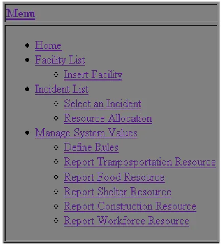
Figure 1 is the system main menu. In the main menu it has three menu items for three
deferent rolls. The first one is for incident reporter to report an incident. The second one is for
the person who is in charge of allocating resource to existing incidents. The last one is for the
system administrator.
Figure 1: System Menu
Figure 2 shows the Administrator menu. It shows the functionalities an administrator can do.
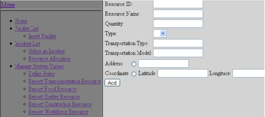
Figure 3 is the “ Report Transportation Resource” menu and Figure 4 is an example of
entering a transportation resource information. In this example we entered the resource
address and it will automatically convert the address to coordinate and save in the database.
After we click “Add” button, the message bar under the menu would show that the resource
Figure 3: Report Transportation Resource
added successfully( Figure 5).
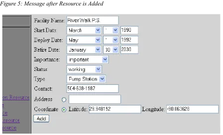
Figure 6 shows an example of adding a facility, we add the coordinate of the facility directly
in this example. After click the “Add” button, there would be a message shows that the
facility added successfully (Figure 7). Then we click on the “Facility List” it will show the
information of the new facility which is stored in the database (Figure 8) .
Figure 6: Example of Adding a Facility Figure 5: Message after Resource is Added
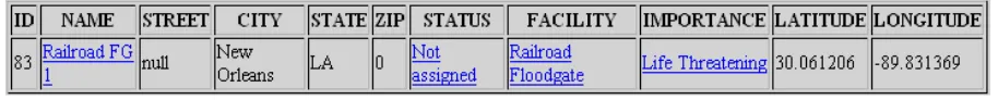
Figure 8: Facility List
In Figure 9 “Raiload FG 1” is reported as an incident. In fact “Railroad FG 1” is a reported
facility and therefore the facility location is used as the location of the incident. This does not
always have to be the case as an incident may be related to a facility but at a different
location. Once the incident is given a name, a date (clearly cannot be greater than today's
date), a facility, an importance, a status and a location the user has to press the “Submit”
button to add the incident to the database. Figure 10 shows the receipt of succession.
To review the addition of the incident, the user is given the menu option to view the list of
incidents. As in Figure 11 the addition of the incident is added to the list of incidents.
Figure 9: Report an Incident
Figure 10: Message after Incident is Reported
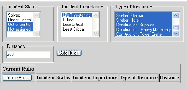
As described in the Resource Allocation section, the user can define rules to engage the “type
of resource”, the “importance of incident” and the “status of the incident” into the decision
making process. By selecting criteria from the drop down menu (multiple selection is
allowed) the user is then to input the within distance for which this rule is in effect. As an
example in Figure 12 the following rule is designed: when Incident Status is “out of control”
or “not assigned” and Incident Importance is “life threatening”, employ all type of
resources that are within 200 miles from the incident. Construction of other rules are similarly
possible.
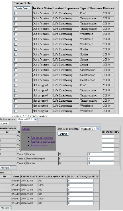
Figure 13 shows the result of submitting this rule. Rules can then be deleted by selection of
the rules and applying the “delete” button on the bottom of the page.
33
Figure 13: Current Rules
The rule table is then used by the application to decide which incidents can have access to
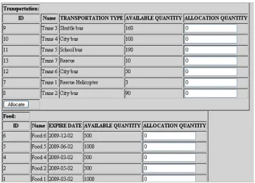
which resources. The next step is to view the resources that could be allocated to a given
incident. From the menu administrator can select the “Resource Allocation” link that leads to
the page shown in Figure 15. In this page, the user can select a single incident to view the
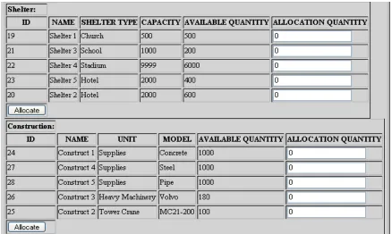
usable resources and to allocate a certain amount of each resource. Figures 16, 17 and 18
show the available resources for the incident “Railroad FG 1” incident. Note that there is a
partition for different types of resources: Transportation, Food, Workforce, Construction and
Shelter.
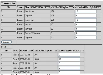
At this point the user can use the text field on the right to allocate an amount up to the amount
shown in the “available quantity” column. For example, in Figure 18 we try to allocate 10
“shuttle bus” from a transportation resource named “Trans 3”. After the user submit using the
“allocate” button, the allocation is registered in the database and the quantity is deducted
from the available quantity for that resource. Figure 19 shows this deduction.
Figure 17: Available Resource for Selected Incident
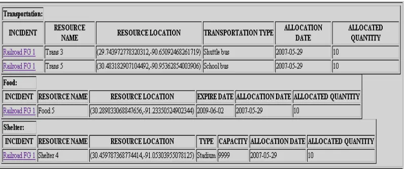
The allocation of resources could be viewed using the administrator menu option “Show
Allocation”. Figure 20 shows the allocation summary for “Railroad FG 1” incident.
MVC Implementation
As mentioned earlier DRS uses the Model-View-Controller (MVC) paradigm. the
“model” is implemented in Oracle Spatial Database, “controller” is implemented in Java
Servlets, and the “view” is implemented in Java Server Pages (JSP). The following sections
are some important implementation specific issues.
Connection Pooling
Most controller objects in database driven applications have to create a new connection to the
database. This process is very time consuming and system resource exhaustive. One way to
cope with this reality is to limit the number of connections.
Connection pool is a class that using a number of JDBC Connection and their access
methods. In other words, connection pool is a container with interface for managing and
controlling database connections. The class, SimpleConnectionPool, creates a
connection pool and it contains a limited set of methods for database connection. the core
functionality is broken down below:
• Allows database specific driver
• Retrieve a reference to the connection pool
• Retrieve a valid connection to the database
• Releaseing the connection
• Destroying and cleaning connections
Note that Jakarta Struts framework has
org.apache.struts.util.GenericDataSource which has a different approach to
the same problem. The constructor of the class SimpleConnectionPool takes at least three
arguments to access a database: URL, user-name and password. The URL is driver specific
and the corresponding URL for the Oracle database is
jdbc:oracle:thin:@serverName:portNumber:schema.
The connection pool is a singleton class, SimpleConnectionPool. Meaning construction of a
connection pool object is done through a qualified method rather than the constructor of the
The loadJDBCDriver() method is simply defined as the following:
getConnection() is used to get a database connection as a Connection object with the
following definition:
private SimpleConnectionPool(String URI, String dbuser, String dbpass, String drivername, int maxconn) { this.URI = URI;
this.dbuser = dbuser; this.dbpass = dbpass;
this.drivername = drivername; this.maxconn = maxconn;
loadJDBCDriver();
}
private void loadJDBCDriver() { try {
Driver driver =
(Driver)Class.forName(this.drivername).newInstance(); DriverManager.registerDriver(driver); } catch (Exception e) {
System.out.println("Can't load/register JDBC driver "); }
In the above segment freeConnections is an ArrayList of Connections and the
method searches this object for any valid connection. First if a connection is found but it is
closed by the database it is removed and the method is called again. If no connection is
found, a new connection is going to be registered with the pool (using
createConnection() method) and the method is called again. At any point if a valid
connection is found it is returned.
createConnection() method is responsible for creating and registering a new database
connection. The following definition is implemented: public synchronized Connection getConnection() {
Connection rescon = null;
if (!this.freeConnections.isEmpty()) { rescon =
(Connection)this.freeConnections.get(this.freeConnections.size()-1);
this.freeConnections.remove(rescon); try {
if (rescon.isClosed()) {
System.out.println("Removed closed connection!");
// Try again recursively rescon = getConnection();
}
} catch (SQLException e) {
System.out.println("Removed closed connection!"); // Try again recursively
rescon = getConnection(); } catch (Exception e) {
System.out.println("Removed closed connection!"); // Try again recursively
rescon = getConnection(); }
} else {
rescon = createConnection(); }
In addition the returnConnection() method returns a connection back to the
connection pool and puts it at the end of the list.
To terminate the use of a connection permanently, one may use release(), which closes
and releases all connections from the connection pool: private Connection createConnection() {
Connection rescon = null; try {
if (this.dbuser == null) {
rescon = DriverManager.getConnection(this.URI); } else {
rescon = DriverManager.getConnection(this.URI, this.dbuser, this.dbpass);
}
// new connection in connection pool created } catch (SQLException e) {
System.out.println("Cannot create a new connection!"); Rescon = null;
}
return rescon; }
public synchronized void returnConnection(Connection con) { if ((con != null) && (this.freeConnections.size() <= this.maxconn)) {
this.freeConnections.add(con); }
}
public synchronized void release() {
Iterator allc = this.freeConnections.iterator(); while (allc.hasNext()) {
Connection con = (Connection)allc.next(); try {
con.close();
} catch (SQLException e) {
System.out.println("Cannot close connection! (Probably already closed?)");
} }
The DRS controller object effectively use the above implementation to achieve the speed and
reliability necessary to carry on the desired task. The adaptation uses the standard life time of
the servlet. During init() phase an instance of SimpleConnectionPool is created
using the getInstance() method, while during the service() phase a call to
getConnection() is made to obtain a valid connection to an already initialized one. The
Connection object is then realeased in the destroy() phase of the servlet.
Geocoder
In DRS the facilities, resources and incidents are identified using their latitude and
longitude. If the user has this information then no further step is taken; However if they user
does not have the latitude and the longitude of the DRS object, he/she has to first convert its
address to the true latitude and longitude coordinates.
The process of converting address to geometric information uses the geocoding
facility explained in the design section [see]. In the MVC diagram of [see] geocoding is done
in the controller. The following section of the actual Java code demonstrates this idea.
This code segment is used whenever a change of address to latitude and longitude is
necessary. the address string is passed to the controller object by the JSP – the view – GeoCoder gc = new GeoCoder();
GeocoderAddressResult[] gar = null; try {
String address = request.getParameterValues("address")[0]; gar = gc.geocode(address);
latitude = gar[0].getLat(); longitude = gar[0].get_long(); city = gar[0].getCity();
street = gar[0].getNumber() + " " + gar[0].getStreet(); state = gar[0].getState();
zip = gar[0].getZip(); } catch (Exception e) {
object. Once the address is known a GeoCoder proxy bean [see] is instantiated and the
geocode(String address) method is called with the address as an argument. Then the
geocode(String address) method returns an array of GeocoderAddressResult objects that
containing the latitude, longitude and the segments of the input address. The segments of the
input address are the zip, state, city and street and street number of the input string. This
information is often necessary since the input address, however unique, is not always
complete. For example consider the following address:
This address is incomplete but is uniquely identified, however, the gar[0].city would return
“matairie” and gar[0].state would return “Louisiana” as part of the missing information.
Once the latitude, longitude and the address information is known, it has to be written to the
Oracle Spatial database. Since the controller object is responsible for all database access this
process is part of a controller object dealing with spatial data. There are two ways to go about
implementing writing spatial data to the oracle database. One way is to use
java.sql.PreparedStatement class in conjunction with oracle.spatial.geometry.JGeometry and
oracle.sql.STRUCT classes. For example to insert the latitude and longitude
(31.97352,-90.53421,8307) of a Facility object to Oracle database the following Java code is used:
String address = “1168 Lake Ave. 70005”
PreparedStatement ps = conn.prepareStatement(
"insert into DM_FACILITY (LOCATION) values(?) where ID=i");
JGeometry geom = new JGeometry(31.97352,-90.53421,8307);
OracleConnection oc = (OracleConnection) ps.getConnection(); STRUCT struct = JGeometry.store( geom, oc);
Another method of writing the same information would be to use SDO_GEOMETRY
construction of Oracle Spatial database without using the Oracle JDBC driver. The following
code demonstrates that:
The first method is the preferred object-oriented method while the second method is useful
when one does not have access to the oracle spatial Java package.
Another part of obtaining the geometric information of DRS objects is to search the Oracle
database for latitude and longitude. Coordinates are stored in the Oracle database using
Oracle Locator SDO_GEOMETRY object [see]. The following Java code demonstrates this
capability by retrieving the latitude and longitude information from the SDO_GEOMETRY
object in the database:
Allocation Table
As it was explained earlier the process of resource allocation follows the process of String insertClause =
"insert into Facility (location) values " + "(" +
"SDO_GEOMETRY(2001,8307,SDO_POINT_TYPE" + "(31.97352,-90.53421,8307,NULL),NULL,NULL)" + ") where id=i";
Statement statement = connection.createStatement(); statement.executeUpdate(insertClause);
Facility sf = ...;
STRUCT dbObj = (STRUCT) rs.getObject("location");
JGeometry geom = JGeometry.load(dbObj); if(geom!=null) {
double gPoint[] = geom.getPoint(); sf.setLatitude(gPoint[0]);
finding available resources to a given incident. Available resources are identified through a
process of filtering those resources that follow a certain rule when matched to every incident
[see]. In this implementation rules are defined in a database table, called
DM_INCIDENT_REGION. This table has 4 columns that refer to incident type
(DM_LK_INCIDENT_TYPE), incident importance (DM_LK_INCIDENT_IMPORTANCE),
resource type (DM_LK_RESOURCE_TYPE) and incident to resource distance in miles. In
words, for a resource to be available to an incident of a particular type and importance, a
particular resource needs to be within a certain distance from that incident. The query that is
employed to retrieve this information is written below:
To retrieve other resources – such as workforce, shelter, food and construction – similar query
is used. The result is then displayed to the user for final allocation decision.
SDO_DISTANCE is a Oracle Spatial function that returns the distance of two
SDO_GEOMETRY objects stored in the database. The third parameter to SDO_DISTANCE
is the error tolerance that is usually set to 0.5 for spatial data, and the fourth parameter is the
distance unit. It is rather cumbersome to calculate the distance between to spatial
coordinates, however, this function with the fourth parameter set to “unit=mile/km” simply
hides this awkwardness. select r_all.*,rt.*
from dm_resource_transport rt, (select r.*
from dm_resources r, dm_incident i,
dm_incident_region ir where i.id=someid AND
ir.i_id=i.importance AND ir.s_id=i.status AND ir.t_id=r.type AND
SDO_GEOM.SDO_DISTANCE
Controller Objects
In DRS entities are mapped directly to their corresponding Java implementations. Each
entity-object is then representative of a record of that entity in the database. In addition,
controller classes are those that are suffixed by “container” and hold one or more
Functionality Summary
Walk Through I
Hurricane cut off electricity power supply in Metairie area. The steps for the user are as
follow:
1. Administrator adds “Power Station” to the facility type through modifying the system
value (Figure21).
2. Insert the facility of the power station of Metairie area in the facility list as type Power
Station (Figure 21). In the facility list the Power Station Metairie will show (Figure
22).
3. Incident reporter goes to the “report an incident” menu to insert the incident that
happened to Power Station Metairie (Figure 23).
Figure 21: Add the facility to the facility list
Figure 22: New Facility added
4. Go to “Resource Allocation” menu to select the incident “P.S. Metairie down”(Figure
24). It will show the available resource for this incident after the user press the
“Submit” button. In this case, the user allocates the resource as shown in the Figure
25.
5. After the user allocated the resources, the available quantity will subtracted by the
amount allocated by the user (Figure 26). Also when we check the amount of resource
that allocated to the incident we will see the Figure 27.
Figure 24: Select the incident to allocate resource
Walk Through II
Pump Station #3 lost power.
1. The Pump Station #3 lost power. The incident reporter will go to the “ Report an
Incident” menu to report this incident to the system as Figure 28.
After reporting this incident, click on the “incident list” , the incident will be shown in
the list (Figure 29).
2. User check the available resources for this incident.
After selecting the incident (Figure 29), press “Submit” button to get the list of the
available resources. We take the available “Construct Resource” as an example here
Figure 28: Report the incident of "Pump Station #3 lost power"
(Figure 30).
In Figure 30 we can see that only three construct resources are available to this
incident. The reason the other two resources are not available to this incident is
because when we set up the “rule table” we set the type of the construct “Tower
Crane” is not available to the “critical” and “not assigned” level incident. The other
two construct resources are “Tower Crane” so it's now available.
In this allocation step we will assign two “Construct 4” and four “Construct 1” to this
incident. After pressing the “Allocate” button the database will change the available
quantity (Figure 31).
3. Check the “Show Use” page to see the resources assigned to this incident (Figure 32).
Figure 30: the available construct
Conclusion
The preliminary system, demonstrated within the previous pages, employs various modern
Object-Oriented software engineering techniques in conjunction with the state of the art
Spatial relational database system to explore the applicability of a disaster response
information system. In terms of software practicability, even though simplified, the
application properly shows the extent to which very organized databases and “smart” pattern
classification methods can submerge to assist decision makers to allocate substantive
resources to reported incidents. The hope is to initiate an effort to fully implement the ideas
presented above into a comprehensive system that can be fully utilized at times of emergency
Appendix A – Eclipse
Introduction
Eclipse is an open-source, platform-independent software framework, written
primarily in Java, for delivering what the project calls "rich-client applications”, as opposed
to "thin client" browser-based applications. So far this framework has typically been used to
develop Integrated Development Environments (IDEs), such as the Java IDE called Java
Development Toolkit (JDT) and compiler (ECJ) that comes as part of Eclipse (and which are
also used to develop Eclipse itself). However, it can be used for other types of client
application as well.
Eclipse is also a community of users, constantly extending the covered application
areas. An example is the recently created Eclipse Modeling Project, covering most areas of
Model Driven Engineering.
Eclipse was originally developed by IBM as the successor to its VisualAge family of
tools. It is now managed by the Eclipse Foundation, an independent not-for-profit consortium
of software industry vendors. Many software tool vendors have embraced Eclipse as a future
framework for their IDEs.
History
Eclipse began as an IBM Canada project. It was developed by OTI (Object
Technology International) as a replacement for VisualAge which itself had been developed by
OTI. In November 2001, a consortium was formed to further the development of Eclipse as
3.0 selected the OSGi Service Platform specifications as the runtime architecture.
In 2006 the Eclipse Foundation coordinated its 10 open-source projects, including the
Eclipse Platform 3.2, to release on a same day. This simultaneous release was known as the
Callisto release. Europa is the simultaneous release of more than 22 open-source projects in
2007.
Architecture
The basis for Eclipse is the Rich Client Platform (RCP). The following components constitute
the rich client platform:
• Core platform: boots Eclipse and runs plug-ins.
• OSGi: A standard bundling framework
• The Standard Widget Toolkit (SWT): A portable widget toolkit
• Jface: Buffers files, handles and edits text
• The Eclipse Workbench: Views, editors, perspectives and wizards
Eclipse's widgets are implemented by a widget toolkit for Java called SWT, unlike most Java
applications, which use the Java standard Abstract Window Toolkit (AWT) or Swing.
Eclipse's user interface also leverages an intermediate GUI layer called JFace, which
simplifies the construction of applications based on SWT.
Eclipse employs plug-ins in order to provide all of its functionality on top of (and including)
the rich client platform, in contrast to some other IDEs where functionality is typically hard
coded. This plug-in mechanism is a lightweight software component-based framework. In
and Python, the plug-in framework allows Eclipse to work with typesetting languages like
LaTeX, networking applications such as telnet and database management systems. The
plug-in architecture supports writing any desired extension to the environment, such as for
configuration management. Java and CVS support is provided in the Eclipse SDK. It does not
have to be used solely to support other programming languages.
The Eclipse SDK includes the Eclipse Java Development Tools, offering an IDE with a
built-in built-incremental Java compiler and a full model of the Java source files. This allows for
advanced refactoring techniques and code analysis. The IDE also makes use of a workspace,
in this case a set of meta-data over a flat file-space allowing external file modifications as
long as the corresponding workspace "resource" is refreshed afterwards.
Web Tools Platform
Eclipse is composed of many different projects. A complete list can be found [see
http://www.eclipse.org/projects/]
In J2EE applications, the use of Web Tools Platform (WTP) project is essential. More
specifically, The Eclipse WTP Project provides APIs for J2EE and Web-centric application
development. It includes both source and graphical editors for a variety of languages, wizards
and built in applications to simplify Web Service development, and tools and APIs to support
deploying, running, and testing applications. WTP can be thought of the extension of the
Eclipse platform with tools for developing Java EE Web applications. It's composed of:
source editors for HTML, Javascript, CSS, JSP, SQL, XML, DTD, XSD, and WSDL;
graphical editors for XSD and WSDL; Java EE project natures, builders, and models and a
Java EE navigator; a Web service wizard and explorer, and WS-I Test Tools; database access