THERMAL ENERGY STORAGE SYSTEM USING PHASE CHANGE MATERIAL: A REVIEW
*
Gargi Sanjay Khot
Mechanical Engineering, SPPU, Sinhgad College of Engineering Pune
ARTICLE INFO ABSTRACT
Thermal energy storage (TES) is becoming a growing concern in modern technology and it has number of applications. Energy storage is essential whenever there is a mismatch between the supply and consumption of energy. Growing energy demands, lack of fossil
increase in the level of greenhouse gas emissions are the main driving forces to practice various sources of renewable energy. Due to irregular and unpredictable nature of solar energy; efficient, economical and reliable solar th
Among the different possibilities to store energy, systems using Phase Change Materials (PCM) can be preferred for its consistency in latent heat storage. The use of PCM is an effective way of thermal energy and has the advantages of having high storage density and the isothermal nature of the storage process. Due to this, the volume of material is reduces and so the cost of the system. But the PCM storage system has low thermal conducti
enhancement techniques should be used. This paper summarise the selection of thermal energy storage systems using phase change material.
Copyright©2016, Gargi Sanjay Khot and Khanwalkar.
unrestricted use, distribution, and reproduction in any medium, provided the original work is properly cited.
INTRODUCTION
Due to unpredictable and unstable nature of
becomes very difficult to satisfy the gap between supply and demand of electricity. The only solution to this problem is to have storage in the system which can satisfy the demand regardless of unavailability of radiation. In storage, t
energy that is not required, is collected and used it during hours when sunlight is not ample to satisfy the demand. Thermal storage can also be used for process application where a waste heat can be stored in thermal storage and used when it is required. Table 1.1 shows the advantages of using thermal energy storage in solar thermal power plant.
Thermal energy storage methods
There are many ways to store thermal energy. They can be divided into:
Sensible heat storage
Latent heat storage
Thermochemical storage
*Corresponding author: Gargi Sanjay Khot,
Mechanical Engineering, SPPU, Sinhgad College of Engineering Pune.
ISSN: 0975-833X
Article History:
Received 23rd June, 2016 Received in revised form 27th July, 2016
Accepted 07th August, 2016
Published online 20th September, 2016
Key words:
Thermal Energy storage, Phase change material, Solar Energy,
Heat Transfer Enhancement, Solar thermal plant.
Citation: Gargi Sanjay Khot and Khanwalkar P.M.
of Current Research, 8, (09), 37884-37889.
RESEARCH ARTICLE
THERMAL ENERGY STORAGE SYSTEM USING PHASE CHANGE MATERIAL: A REVIEW
Gargi Sanjay Khot and Khanwalkar P.M.
Mechanical Engineering, SPPU, Sinhgad College of Engineering Pune
ABSTRACT
Thermal energy storage (TES) is becoming a growing concern in modern technology and it has number of applications. Energy storage is essential whenever there is a mismatch between the supply and consumption of energy. Growing energy demands, lack of fossil
increase in the level of greenhouse gas emissions are the main driving forces to practice various sources of renewable energy. Due to irregular and unpredictable nature of solar energy; efficient, economical and reliable solar thermal energy storage devices and methods have to be developed. Among the different possibilities to store energy, systems using Phase Change Materials (PCM) can be preferred for its consistency in latent heat storage. The use of PCM is an effective way of thermal energy and has the advantages of having high storage density and the isothermal nature of the storage process. Due to this, the volume of material is reduces and so the cost of the system. But the PCM storage system has low thermal conductivity which leads to poor heat transfer so heat transfer enhancement techniques should be used. This paper summarise the selection of thermal energy storage systems using phase change material.
. This is an open access article distributed under the Creative Commons Att use, distribution, and reproduction in any medium, provided the original work is properly cited.
Due to unpredictable and unstable nature of solar radiation, it becomes very difficult to satisfy the gap between supply and demand of electricity. The only solution to this problem is to have storage in the system which can satisfy the demand regardless of unavailability of radiation. In storage, the extra energy that is not required, is collected and used it during hours when sunlight is not ample to satisfy the demand. Thermal storage can also be used for process application where a waste heat can be stored in thermal storage and used when it equired. Table 1.1 shows the advantages of using thermal
There are many ways to store thermal energy. They can be
Mechanical Engineering, SPPU, Sinhgad College of Engineering
Sensible heat storage
In sensible heat storage, the thermal energy is stored due to increase in temperature of stored
energy stored depends on the specific heat, the change in temperature and mass of the material.
Q = ∫
Sensible heat storage can be differentiated on the basis of storage media, viz. (i) liquids such as oil, water and
salt, and (ii) solids such as rocks and metals.
Latent heat storage
Latent heat storage system (LHS) uses the energy released or absorbed in the phase change region. When the material reaches the phase change temperature it absorbs or releases a huge amount of energy to carry out the phase change which is known as the latent heat of fusion or evaporation depending on the state and in this way the energy is stored. The materials used are known as phase change materials (PCM). They have very high energy density and hence they reduce the volume and hence the cost. Figure 2.2.1
mechanism of a PCM. When a solid is heated, its temperature rises up to its melting temperature.
International Journal of Current Research Vol. 8, Issue, 09, pp.37884-37889, September, 2016
P.M., 2016. “Thermal energy storage system using phase change material: A review
THERMAL ENERGY STORAGE SYSTEM USING PHASE CHANGE MATERIAL: A REVIEW
Mechanical Engineering, SPPU, Sinhgad College of Engineering Pune
Thermal energy storage (TES) is becoming a growing concern in modern technology and it has number of applications. Energy storage is essential whenever there is a mismatch between the supply and consumption of energy. Growing energy demands, lack of fossil fuels, and the continuous increase in the level of greenhouse gas emissions are the main driving forces to practice various sources of renewable energy. Due to irregular and unpredictable nature of solar energy; efficient, ermal energy storage devices and methods have to be developed. Among the different possibilities to store energy, systems using Phase Change Materials (PCM) can be preferred for its consistency in latent heat storage. The use of PCM is an effective way of storing thermal energy and has the advantages of having high storage density and the isothermal nature of the storage process. Due to this, the volume of material is reduces and so the cost of the system. But the vity which leads to poor heat transfer so heat transfer enhancement techniques should be used. This paper summarise the selection of thermal energy
open access article distributed under the Creative Commons Attribution License, which permits
In sensible heat storage, the thermal energy is stored due to stored medium. The amount of energy stored depends on the specific heat, the change in temperature and mass of the material.
Sensible heat storage can be differentiated on the basis of liquids such as oil, water and molten salt, and (ii) solids such as rocks and metals.
Latent heat storage system (LHS) uses the energy released or absorbed in the phase change region. When the material reaches the phase change temperature it absorbs or releases a huge amount of energy to carry out the phase change which is nt heat of fusion or evaporation depending on the state and in this way the energy is stored. The materials used are known as phase change materials (PCM). They have very high energy density and hence they reduce the volume and hence the cost. Figure 2.2.1 explains the energy storage mechanism of a PCM. When a solid is heated, its temperature rises up to its melting temperature.
OF CURRENT RESEARCH
Table 1.1. Advantages of thermal energy storage in a solar thermal plant (F. Dinter and D. M. Gonzalez, 2014)
(1) Prevention of interruption due to intermittency
of solar radiation
Compared to PV, power output of CSP with storage does not depend on the current solar radiation. So the power fed in grid can be kept constant despite of strong fluctuations in radiation. This becomes even more important in regions with strong fluctuations in weather
(2) Shifting of power generation to peak periods
and 24 hours per day of production
Since energy prices depend on its demand, TES enables a solar thermal plant to produce power during peak hours and increase the revenue. It can do this by avoiding power generation during low or negative energy prices
(3) Regulation and frequency response Regulation and frequency response is generally done by conventional fossil fired plants. CSP
generation units can provide the same due to their inertia and response governors
(4) Support for power quality Power systems require reactive power for supporting and maintaining voltage levels. Other
energy sources reduce the inertia of the system which can cause faster and larger frequency deviations due to sudden variation in generation and load. CSP with TES can provide quality power through reactive power support and inertia response.
(5) Support to other renewable energy sources Due to increasing penetration of wind and solar photovoltaic generation, there is an increase
in variability of power supply. CSP with TES can help such sources by providing support to them.
(6) Generation of power independent of weather
condition and time
CSP without storage can produce power only during hours when solar radiation is available.
(7) Improved economics Due to more hours of power generation, revenues are more and hence the payback time is
[image:2.595.187.425.282.500.2]reduced
Fig.2.2.1. Temperature profile of a PCM with heat supply
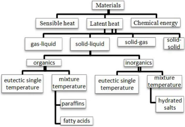
Fig.2.3.1. Classification of TES materials (Sharma et al., 2009)
[image:2.595.153.460.548.759.2]After this point the temperature come to an end to increases and the phase change occurs. After the PCM has completely melted, the temperature rises again up till it reaches the boiling temperature. After this the temperature remains constant till everything is evaporated. In PCM application one can give and extract the energy within the phase change region and therefore without changing the temperature.
Q = ∫ _ + mLm + ∫ _
The 1st term represents the increase in sensible energy
stored by the increase in temperature of material from initial temperature to melting temperature.
The 2nd term represents the latent energy stored in the
material by phase change.
The 3rd term represents the sensible energy stored by
increase in temperature.
Most of the PCM suffer from a constraint of low
thermal conductivity of around 0.2 and 0.5 W/mK for paraffin and inorganic salts respectively.
Thermochemical heat storage
This is the most underdeveloped method of thermal energy storage. It contains the use of endothermic chemical reactions. When heat is supplied to an appropriate material, it is utilised in breaking the chemical bonds of the compound. Later all of this energy is recovered when the reaction takes place. This technology offers various advantages but it is in the early stages of development. The different types of PCMs are classified in figure 2.3.1.
Classification of PCM
The materials used in latent heat application are known as phase change material (PCM). They may undergo the following transformations:
Solid-solid (Ex. Cellulose diacetate)
Solid-liquid (Ex. Paraffin)
Liquid-gas (Ex. Water)
Solid-solid PCM
Solid-solid PCM materials transform their crystalline structure at a particular temperature. The transformation energy is comparable to the best solid to liquid PCMs. They are very easy to handle and cost effective because the absence of liquid state eliminates the problem of leakage and need for encapsulation. Research is going on for developing steel alloy for such application (T. Nomura, et, al, 2010).
Liquid-gas latent heat storage
The transformation from liquid to gaseous state requires the highest amount of energy. But due to enormous amount of change in volume, the economic and practical feasibility becomes very difficult. Also, not much information is available on the gaseous state of materials.
Solid-liquid latent heat storage
The transition of materials from solid to liquid is studied and used widely in latent heat storage applications.
Even though they have several times less latent heat compared to liquid-gas PCMs, they are acceptable as they do not present technical and economic difficulties of expansion. Normally their expansion is less than 10% of their original volume. There are many problems associated with the use of solid-liquid PCM such as the complexity of the container, phase segregation and subcooling. But, the biggest hurdle to its application is the low thermal conductivity. It restricts the extraction and storage of the energy in a limited time period and also leads to wastage of PCM material by remaining unused.
Parameters for selection of PCM
Some points should be taken care while selecting a PCM for appropriate application (F. Agyenim, et, al, 2010), which are as follows:
Melting temperature near our requirement
High latent heat of fusion
Low specific heat
High thermal conductivity in solid state, so that the heat
is diffused in lesser time
Low thermal expansion coefficient so that design
becomes easier and cheaper materials can be used for containing it
Low or zero subcooling during freezing
Non-poisonous, non-explosive and non-flammable
Cheap and easily available
PCM container
After the PCM has been selected, the factors to consider are:
Design of the PCM container
The thermal and geometric parameters of the container
required for a given amount of PCM
These factors have great role in influencing the parameters of heat transfer. PCMs are kept in long thin heat pipes (B.
Horbaniuc, et, al 1999), cylindrical containers (E.
Papanicolaou and V. Belessiotis2002), (F. Agyenim, et, al, 2009) or rectangular containers (P. D. Silva, et, al, 2002), (K.Ermis, A., et, al, 2007) as shown in figure 5.1. Rectangular and cylindrical containers are the most common shapes of container. Among them shell and tube system is the most commonly used one, which accounts for more than 70%.
The cylindrical PCM container can be used in the following ways:
In the 1st configuration, the PCM is on the shell side and
heat transfer fluid flows inside the tube(M. Esen, et, al, 1998)
In the 2nd configuration, the PCM is in the tube and the
HTF flows on the shell side. According to Esen et al.(M. Esen, et, al, 1998), the pipe model is better because it took less time to melt.
The 3rd model is the shell and tube system. It is commonly
conducted experiments with horizontal shell and tube heat exchanger (4 tubes) and a pipe model (F. Agyenim, et al, 2010). Heat transfer in the shell and tube system was better. The reason for this was found to be multiple convective heat transfer.
Fig.5.1. Commonly used PCM containers (F. Agyenim, et al., 2010)
Comparison of counter-current and parallel heat transfer fluid (HTF) flow directions
In a cylindrical assembly, the HTF can flow in two directions during charging and discharging of the PCM, viz. (a) hot and cold streams are entered from same direction, and (b) hot and cold streams are entered from opposite direction. Gong and Mujumdar (Z.X. Gong and A. S. Mujumdar 1997) conducted numerical simulations to find the effect of the parallel and counter-current flow modes. They found that parallel flow increases the energy charge/discharge rate by 5% more than counter-current flow.
Fig.6.1: Comparison of parallel and counter flow (F. Agyenim et al., 2010)
Heat transfer enhancement techniques
Most of the PCM suffers from low thermal conductivity which leads to very poor heat transfer coefficient. In order to overcome this problem, heat transfer enhancement techniques are used as shown in figure 7.1, such as,
Finned tubes
Bubble agitation
Insertion of a metal matrix in the PCM
PCM dispersed with high conductivity particles
Micro-encapsulation of the PCM
Shell and tube
Fig.7.1: Common heat transfer enhancement technique (F. Agyenim et al. 2010)
It should be noted that different researchers used different experimental setups and different materials of PCM and container. Also, researchers used different parameters to assess the heat transfer enhancement in the PCMs. (Velrajet, al, 1999)evaluated the performance by calculating the effective thermal conductivity. Horbaniuc et al, evaluated the performance of fins in terms of time taken for complete solidification. (Choi and Kim J. C., et, al, 1992) used the ratio of overall heat transfer coefficient in the finned and unfinned tube systems.
Extended surfaces
Most of the people use fins in PCM as it is simple to manufacture as well as they are cheap. The best improvement in heat transfer was reported by Velraj et al. where the thermal conductivity was improved by 10 times (Velraj et, al, 1999). It was observed that there is no degradation of the material after
testing more than 400 h with NaNO3 as PCM (W.D.
Steinmann, D. Laing, and R. Tamme2009). Both, aluminium and graphite sheets did not get corroded due to the contact with the galvanized steel of the pipes. Steel fins occupy more volume than graphite fins for same heat transfer. The cost of steel fins is significantly higher because of this. Mostly encapsulation is used in low temperature materials. It is costly
to encapsulate PCM with melting temperatures above 200 0C.
The initial volume of PCM should not be more than 80% of the capsule volume while using a rigid capsule. By doing this, it is ensured that capsule can withstand the pressure exerted.(R. Steinmann and Tamme2003)
Multiple PCM method
Multiple PCM technique contains more than one PCM having different melting temperatures in the LHS unit. The heat transfer rate is decided by the difference in the temperature of the HTF and the PCM melting point(S. Jegadheeswaran and S. D. Pohekar2009). single PCM is used, heat transfer becomes poor because temperature difference decreases in the flow direction of the HTF. In order to keep a constant temperature difference during the melting process, multiple PCMs should be used in decreasing order by their melting points. This leads to a nearly constant heat flow to the PCM. When HTF is flowed in reverse direction during discharge, the PCMs remain in the increasing order of their melting points, and almost constant heat flow happens from the PCM to the HTF. Figure 7.2.1 shows how we can use multiple PCMs in a shell and tube configuration.
Fig.7.2.1. LHS system with multiple PCM (Seeniraj et al., 2002)
Farid and Kanzawa (Faridand and Kanzawa1989) used 3 PCMs with different melting points in cylindrical capsules. Air was used as HTF. A 10% increase in heat transfer rate was obtained during charging and discharging. Michels and Pitz-Paal (Michels and
experimented with 3 PCMs on shell side and synthetic oil in the inner tube. Most of the PCM melted during the experiment.
to choose right combination of PCMs. For this we require an appropriate difference between the melting points and proper amounts of PCM. Fang and Chen (M. Fang and G. Chen, 2007) performed a numerical study in a shell and tube module to examine the effect of different combinations of PCM. The results showed that it is best to have more melting point difference between the PCMs.
use multiple PCM along with extended surfaces for even better enhancement (Seeniraj et al., 2002). Hence more studies are needed to investigate and find a combination of PCM with even better performance along with extended surfaces.
Melting process in the PCM
In order to work with PCM, it is very important to understand the process of melting. (Zhang and Bejan1989) together with (Sari and Kaygusuz 2003), (Agyenim et al. 2010) and (Hirata and Nishida 1989) described the melting process in following stages:
Sensible heating at starting increases the temperature of
solid PCM. Pure conduction heat transfer occurs during this
After some time a second conduction regime is formed
in which heat is purely transferred by conduction from the heated wall to the PCM. Solid-liquid interface is formed when melting had just begun
As the thickness of the melt layer increases transition
from conduction to natural convection starts. At the interface, there exists equilibrium between solid body and a pool of its own liquid
Multiple PCM technique contains more than one PCM having different melting temperatures in the LHS unit. The heat transfer rate is decided by the difference in the temperature of the HTF and the PCM melting point(S. Jegadheeswaran and S. D. Pohekar2009). If a single PCM is used, heat transfer becomes poor because temperature difference decreases in the flow direction of the HTF. In order to keep a constant temperature difference during the melting process, multiple their melting points. This leads to a nearly constant heat flow to the PCM. When HTF is flowed in reverse direction during discharge, the PCMs remain in the increasing order of their melting points, and almost constant heat flow e HTF. Figure 7.2.1 shows how we can use multiple PCMs in a shell and tube configuration.
LHS system with multiple PCM
Kanzawa1989) used 3 PCMs with different melting points in cylindrical capsules. Air was used as HTF. A 10% increase in heat transfer rate was obtained during charging and (Michels and Pitz-paal2007) Ms on shell side and synthetic oil in the inner tube. Most of the PCM melted during the experiment. It is necessary to choose right combination of PCMs. For this we require an appropriate difference between the melting points and proper amounts g and Chen (M. Fang and G. Chen, 2007) performed a numerical study in a shell and tube module to examine the effect of different combinations of PCM. The results showed that it is best to have more melting point difference between the PCMs. It is best to se multiple PCM along with extended surfaces for even better , 2002). Hence more studies are needed to investigate and find a combination of PCM with even better
In order to work with PCM, it is very important to understand the process of melting. (Zhang and Bejan1989) together with (Sari and Kaygusuz 2003), (Agyenim et al. 2010) and (Hirata and Nishida 1989) described the melting process in following
Sensible heating at starting increases the temperature of solid PCM. Pure conduction heat transfer occurs during
After some time a second conduction regime is formed in which heat is purely transferred by conduction from liquid interface is
As the thickness of the melt layer increases transition from conduction to natural convection starts. At the interface, there exists equilibrium between solid body
A convection regime is formed when most of the solid
has been melted and the liquid core temperature distribution depends on height.
Conclusion
From the literature survey, it is observed that very few experimental studies are done on thermal enhancement techniques with phase change material (PCM). Mostly paraffin is used as PCM for low temperature application (<100 Hence there is need to do more research in PCM storage with thermal enhancement in the temperature range of 150º C to 200º C.Things that should be taken care while designing a storage system with PCM are as follows:
Choose PCM of good thermal conductivity and high
latent heat of fusion
Shell and tube type container is preferable
If PCM is to be used, use of heat transfer enhancement
technique is must. Out of all the options, extended surface is easy to implement.
Parallel heat transfer fluid (HTF) flow direction is better
compared to counter one.
REFERENCES
Agyenim, F., Eames, P. and Smyth, M.
of heat transfer enhancement in a medium temperature thermal energy storage heat exchanger using fins,
Energy, vol. 83, no. 9, pp. 1509
Agyenim, F., Eames, P. and Smyth, M. 2010. Heat transfer enhancement in medium temperatu
storage system using a multitube heat transfer array,
Renew. Energy, vol. 35, no. 1, pp. 198
Agyenim, F., Hewitt, N., Eames, P. and Smyth, M. 2010. A review of materials, heat transfer and phase change problem formulation for latent
systems (LHTESS), vol. 14, pp. 615 Choi, J. C. and Kim, S. D. 1992. Heat
of a latent heat storage system using MgCl2 • 6H2O,
Energy, vol. 17, no. 12, pp. 1153
Dinter, F. and Gonzalez, D. M. 20
and Economic Benefits of CSP with Thermal Energy Storage: First Year of Operation of ANDASOL 3,
Procedia, vol. 49, pp. 2472–
Ermis, K., Erek, A. and Dincer, I. 2007. Heat transfer analysis of phase change process in
storage system using artificial neural network,
Mass Transf., vol. 50, no. 15
Esen, M., Durmuş, A. and Durmuş, A. 1998. Geometric design of solar-aided latent heat store depending on various parameters and phase change materials,
62, no. 1, pp. 19–28.
Fang, M. and Chen, G. 2007. Effects of different multiple PCMs on the performance of a latent thermal energy storage system, Appl. Therm. Eng.
994–1000.
Farid, M. M. and Kanzawa, A. 1989. Thermal Performance of a Heat Storage Module Using PCM’s With Different Melting Temperatures: Mathematical Modeling,
Energy Eng., vol. 111, no. 2, p. 152.
onvection regime is formed when most of the solid has been melted and the liquid core temperature distribution depends on height.
From the literature survey, it is observed that very few experimental studies are done on thermal enhancement hniques with phase change material (PCM). Mostly paraffin is used as PCM for low temperature application (<100 ˚C). Hence there is need to do more research in PCM storage with thermal enhancement in the temperature range of 150º C to uld be taken care while designing a storage system with PCM are as follows:
Choose PCM of good thermal conductivity and high
Shell and tube type container is preferable
If PCM is to be used, use of heat transfer enhancement is must. Out of all the options, extended surface is easy to implement.
Parallel heat transfer fluid (HTF) flow direction is better compared to counter one.
Agyenim, F., Eames, P. and Smyth, M. 2009. A comparison of heat transfer enhancement in a medium temperature thermal energy storage heat exchanger using fins, Sol.
, vol. 83, no. 9, pp. 1509–1520.
Agyenim, F., Eames, P. and Smyth, M. 2010. Heat transfer enhancement in medium temperature thermal energy storage system using a multitube heat transfer array,
, vol. 35, no. 1, pp. 198–207.
Agyenim, F., Hewitt, N., Eames, P. and Smyth, M. 2010. A review of materials, heat transfer and phase change problem formulation for latent heat thermal energy storage systems (LHTESS), vol. 14, pp. 615–628.
Choi, J. C. and Kim, S. D. 1992. Heat-transfer characteristics of a latent heat storage system using MgCl2 • 6H2O,
, vol. 17, no. 12, pp. 1153–1164.
Dinter, F. and Gonzalez, D. M. 2014. Operability, Reliability and Economic Benefits of CSP with Thermal Energy Storage: First Year of Operation of ANDASOL 3, Energy
–2481
Ermis, K., Erek, A. and Dincer, I. 2007. Heat transfer analysis of phase change process in a finned-tube thermal energy storage system using artificial neural network, Int. J. Heat
, vol. 50, no. 15–16, pp. 3163–3175.
Esen, M., Durmuş, A. and Durmuş, A. 1998. Geometric design aided latent heat store depending on various meters and phase change materials, Sol. Energy, vol.
Fang, M. and Chen, G. 2007. Effects of different multiple PCMs on the performance of a latent thermal energy
Appl. Therm. Eng., vol. 27, no. 5–6, pp.
, M. M. and Kanzawa, A. 1989. Thermal Performance of a Heat Storage Module Using PCM’s With Different Melting Temperatures: Mathematical Modeling, J. Sol.
Gong, Z.X. and Mujumdar, A. S. 1997. Finite-element analysis of cyclic heat transfer in a shell-and-tube latent heat energy storage exchanger, Appl. Therm. Eng., vol. 17, no. 6, pp. 583–591.
Hirata, T. and Nishida, K. 1989. An analysis of heat transfer using equivalent thermal conductivity of liquid phase during melting inside an isothermally heated horizontal cylinder, Int. J. Heat Mass Transf., vol. 32, no. 9, pp. 1663–1670.
Horbaniuc, B., Dumitrascu, G. and Popescu, A. 1999. Mathematical models for the study of solidification within a longitudinally finned heat pipe latent heat thermal storage system, Energy Convers. Manag., vol. 40, no. 15–16, pp. 1765–1774.
Jegadheeswaran, S. and Pohekar, S. D. 2009. Performance enhancement in latent heat thermal storage system : A review, vol. 13, pp. 2225–2244.
Michels, H. and Pitz-paal, R. 2007. Cascaded latent heat storage for parabolic trough solar power plants, vol. 81, pp. 829–837.
Nomura, T., Okinaka, N. and Akiyama, T. 2010. Technology of Latent Heat Storage for High Temperature Application: A Review, ISIJ Int., vol. 50, no. 9, pp. 1229–1239.
Papanicolaou, E. and Belessiotis, V. 2002. Transient natural convection in a cylindrical enclosure at high Rayleigh numbers, Int. J. Heat Mass Transf., vol. 45, no. 7, pp. 1425–1444.
Sarı, A. and Kaygusuz, K. 2002. Thermal and heat transfer characteristics in a latent heat storage system using lauric acid, Energy Convers. Manag., vol. 43, no. 18, pp. 2493– 2507.
Seeniraj, R. V., Velraj, R. and Narasimhan, N. L. 2002 Thermal analysis of a finned-tube LHTS module for a solar dynamic power system, vol. 38.
Sharma, A., Tyagi, V., Chen, C.R. and Buddhi, D. 2009. Review on thermal energy storage with phase change materials and applications, Renewable and Sustainable
Energy Review, Vol.13 (2), pp. 318–345
Silva, P. D., Gonçalves, L. and Pires, L. 2002. Transient behaviour of a latent-heat thermal-energy store: numerical and experimental studies, Appl. Energy, vol. 73, no. 1, pp. 83–98.
Steinmann, R. and Tamme, W.D. 2003. Latent heat storage for solar steam systems, Sol. Energy Eng., vol. 130, pp. 1–5. Steinmann, W.D., Laing, D. and Tamme, R. 2009.
Development of PCM Storage for Process Heat and Power Generation, J. Sol. Energy Eng., vol. 131, no. 4, p. 041009. Velraj, R., Seeniraj, R. V., Hafner, B., Faber, C. and
Schwarzer, K. 1999. Heat Transfer Enhancement In A Latent Heat Storage System, Sol. Energy, vol. 65, no. 3, pp. 171–180.
Zongqin, Z. and Bejan, A. 1989. The problem of time-dependent natural convection melting with conduction in the solid, Int. J. Heat Mass Transf., vol. 32, no. 12, pp. 2447–2457.