3D Printed Titanium Implants
A thesis
submitted in partial fulfilment
of the requirements to obtain the Degree of
Doctor of philosophy By
Seamus John Tredinnick
Department of Mechanical Engineering University of Canterbury
Preface
Abstract
3D printing in medicine has changed the paradigm of modern implant design. Using a combination of advanced imaging and digital fabrication, orthopaedic implants such as prosthetic hip replacements are able to be matched to individual patient’s anatomy and other complex requirements. This emerging technology gives surgeons and engineers a broad scope to explore implant designs that address the long-standing issue of stress shielding by using scaffold materials that encourage bone ingrowth and remodelling. However, the factors that influence how porous 3D printed titanium implants interact with bone need to be further understood to ensure that patients are offered safe and effective treatments.
This research develops porous 3D printed materials using electron beam melted titanium intended for use in orthopaedic implants, from concept through to demonstration of efficacy in vivo. The clinical, regulatory and commercial requirements of porous 3D printed titanium implants were explored, along with considerations for design for additive manufacturing. Materials with both traditional and contemporary scaffold topologies were developed to isolate the effect of the porous design from other factors such as overall porosity or pore size. A translational pre-clinical model was established and the biological performance of the materials was determined in vivo.
Acknowledgements
First and foremost, I would like to sincerely thank my primary supervisor Distinguished Professor Dr J. Geoffrey Chase. Your forbearance let me follow my dreams.
Thank you to my external supervisors, Dr Timothy Woodfield and Dr George Dias of University of Otago, for your expertise. In particular, Tim, your passion for your work is contagious and I am thankful for so much of your time that you generously gave me. Dr Mia Woodruff of Queensland University of Technology, thank you for the year I spent at your laboratory. It was a joy to watch you inspire your students.
I would like to make special mention to Paul Morrison and Mr P. James Burn. In my eyes, you are making the one of the greatest contributions to orthopaedic medicine that a couple of mates from Christchurch could ever hope to achieve. It is my pleasure to be a part of that, and it is a privilege to call you my friends.
To Andy Christensen and Ryan Kircher, thank you for the countless emails and phone calls to offer advice and insight. I owe you a beer. Dr Brent Higgins and Dr Robin McFarlane, your help was instrumental to the success of this project. Brent, thank you for challenging me to help our furry friends and then choosing to make a business out of it with me. The world is a better place because of your passion to help people and animals alike.
A special ‘thank you’ to my dear friends for asking how my thesis was going every time we met. It takes a village to write a thesis.
To my beautiful wife, Emily, it’s finally done! Thank you for being my best friend. Your love and endless encouragement has given me the strength to complete this thing.
Publications
G. I. Brierly, S. Tredinnick, A. Lynham, and M. A. Woodruff, “Critical Sized Mandibular Defect Regeneration in Preclinical In Vivo Models,” Curr. Mol. Biol. Reports, vol. 2, no. 2, pp. 83–89, Apr. 2016.
Conference Proceedings
S. J. Tredinnick and J. G. Chase, “Micro Computed Tomography Based Quantification of
Pore Size in Electron Beam Melted Titanium Biomaterials,” Biol. Med. Syst., vol. 8, pp. 403– 407, 2012.
S. J. Tredinnick, M. A. Woodruff, T. B. F. Woodfield, and J. G. Chase, “Proceedings of the
Posters and abstracts
S. J. Tredinnick and T. B. F. Woodfield, “Osseointegration of pre-clinical electron beam melted titanium scaffolds,” in 23rd Annual Conference of the Australasian Society of Biomaterials and Tissue Engineering, 22-24 April 2014, Mantra Resort Lorne, VIC. (Oral),
2014.
S. J. Tredinnick, M. A. Woodruff, T. B. F. Woodfield, and J. G. Chase, “Rapid
Osseointegration of Titanium Scaffolds in a Sheep Model,” in Combined 22nd Annual Conference of the Australasian Society for Biomaterials & Tissue Engineering and 5th
Indo-Australian Conference on Biomaterials, Implants, Tissue Engineering and Drug Delivery
Systems, 2-5 April 2013. (Oral), p. 78.
S. J. Tredinnick, G. Dias, J. G. Chase, and T. B. F. Woodfield, “Improving the
Osseointegration of Titanium with Electron Beam Melting Technology,” in 21st Annual Australasian Society for Biomaterials & Tissue Engineering, Queenstown, New Zealand, April
Table of Contents
1 Introduction ... 17
1.1 Overview ... 17
1.2 Background ... 19
1.2.1 Titanium in Orthopaedics ... 19
1.2.2 Stress Shielding ... 20
1.2.3 Porosity and Bone Ingrowth ... 21
1.2.4 Bone Tissue Scaffolds ... 22
1.2.5 Material Characterization ... 22
1.2.6 Manufacturing ... 23
1.2.7 Pre-clinical Studies ... 24
1.2.8 Evaluating Bone Ingrowth ... 25
1.2.9 Evaluating Interface Strength ... 27
1.3 Summary ... 27
2 Problem Statement and Context ... 29
2.1 Introduction ... 29
2.2 Regulatory Requirements ... 30
2.3 Clinical Performance ... 31
2.4 Ancillary Requirements ... 33
2.5 Summary ... 36
2.6 Problem Statement ... 36
3 Material Concepts ... 38
3.1 Introduction ... 38
3.2 Cross Hatched Lattice (CH) ... 44
3.3 Modified Dodecahedron (D1 and D2) ... 46
3.4 As Grown (AG) ... 51
3.5 Summary ... 51
4 Characterization ... 53
4.1 Introduction ... 53
4.2 Metallurgical Analysis ... 54
4.3 Physical Properties of the Substrate Surface ... 55
4.3.1 Surface analysis ... 55
4.3.2 Surface features ... 56
4.3.3 Surface roughness ... 62
4.4 Pore Parameters ... 63
4.4.1 Micro computed tomography ... 63
4.4.2 Results summary ... 67
4.4.3 Novel methods and metrics of evaluation ... 67
4.5 Summary ... 69
5 In Vivo Model Background ... 71
5.1 Introduction ... 71
5.2 Animal model review ... 73
5.2.1 Rat ... 77
5.2.2 Rabbit ... 79
5.2.3 Dog ... 81
5.2.4 Pig ... 83
5.2.5 Goat ... 84
5.2.6 Sheep ... 85
5.3 Summary ... 87
5.4 Recommendations ... 91
6.1 Introduction ... 93
6.2 Cadaver ... 93
6.2.1 Introduction ... 93
6.2.2 Methods ... 94
6.2.3 Results ... 95
6.2.4 Recommendations ... 97
6.3 Pilot Animal ... 97
6.3.1 Anaesthesia ... 98
6.3.2 Instrumentation ... 98
6.4 Summary ... 100
7 In Vivo Trial ... 101
7.1 Introduction ... 101
7.2 Study design ... 101
7.2.1 Aims ... 101
7.2.2 Study type ... 102
7.2.3 Time points ... 102
7.2.4 Treatment groups ... 102
7.2.5 Sample Size ... 103
7.3 Animal model ... 104
7.4 Surgery protocol ... 106
7.5 Complications ... 107
7.6 Sample collection ... 108
7.7 Summary ... 108
8 Mechanical Testing ... 127
8.1 Introduction ... 127
8.2 Sample groups ... 128
8.3 Methods ... 129
8.3.1 Sample preparation ... 129
8.3.2 Mechanical test machine ... 129
8.3.3 Push-out test rig ... 129
8.3.4 Sample measurement ... 132
8.3.5 Mechanical testing ... 132
8.3.6 Shear strength calculations ... 133
8.3.7 Statistics ... 134
8.4 Results ... 134
8.4.1 Sample preparation ... 134
8.4.2 Failure mode analysis ... 134
8.4.3 Ultimate shear stress ... 135
8.4.4 Energy to failure ... 136
8.5 Discussion ... 137
8.6 Summary ... 140
9 Histological Findings ... 141
9.1 Introduction ... 141
9.2 Sample groups ... 143
9.3 Methods ... 143
9.3.1 Sample preparation ... 143
9.3.2 Processing ... 145
9.3.3 Sectioning ... 146
9.3.4 Staining ... 149
9.3.5 Imaging and ROI preparation ... 149
9.3.6 Histomorphometry ... 151
9.3.7 Statistics ... 152
9.4.1 Staining optimization ... 153
9.4.2 Histological assessment ... 159
9.4.3 Bone ingrowth ... 161
9.4.4 Bone to implant contact ... 161
9.5 Discussion ... 162
9.6 Summary ... 164
10 Conclusions ... 166
Table of Tables
Table 1: Regulatory requirements for bone tissue scaffolds ... 31
Table 2: Clinical requirements for bone tissue scaffolds. ... 33
Table 3: Ancillary requirements for bone tissue scaffolds ... 36
Table 4: Summary of pore characterisation for all scaffold concepts ... 67
Table 5: A review of animal models for evaluating bone tissue scaffolds. ... 74
Table 6: A summary of the advantages of various animal models. ... 88
Table 7: Actual diameters of individual sample groups. ... 96
Table 8: Assessment of implant stability at various degrees of interference fit. ... 97
Table 9: Sample groups and properties. ... 102
Table 10: Summary of sample numbers and evaluation time points. ... 104
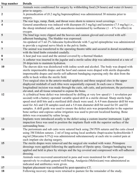
Table 11: Surgical protocol. ... 107
Table 12: Sample groups and properties, repeated from Table 9, Chapter 7. ... 128
Table 13: Test parameters for biomechanical push-out testing. ... 129
Table 14: Sample measurements for push-out calculations. ... 132
Table 15: Interfacial shear stress of sample groups across all time points. ... 136
Table 16: Energy to failure of sample groups across all time points. ... 137
Table 17: Interface strength of commercially available ingrowth and on growth technologies. ... 138
Table 18: Sample groups and properties, repeated from Table 9, Chapter 7. ... 143
Table 19: Histological processing and embedding protocol ... 146
Table 20: Goldner's trichrome staining protocol. ... 149
Table 21: Bone ingrowth of sample groups across all time points. ... 161
Table of Figures
Figure 1: Digital anatomical model derived from CT scan data showing remaining bony anatomy following maxillary sinus tumour resection (left) and concept sketches of a corresponding patient specific implant (right). ... 39 Figure 2: A prototype patient specific maxillofacial implant printed using electron beam
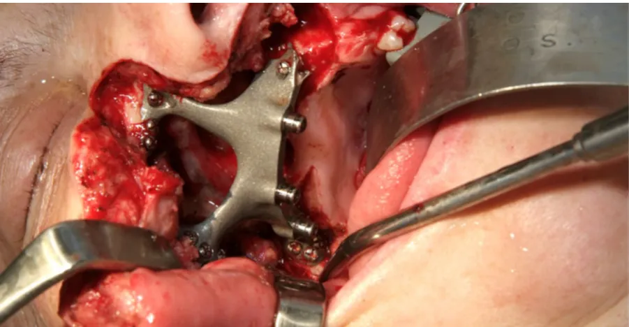
melting and anatomical model printed using fused deposition modeling, as reported in The Press [117]. ... 40 Figure 3: The definitive maxillofacial implant in situ during reconstructive surgery. The
implant was produced using electron beam melting and finished using traditional
machining techniques. The bone interface was left as grown. ... 41 Figure 4: CAD model of an implant to replace an inflamed spinal disc during an anterior
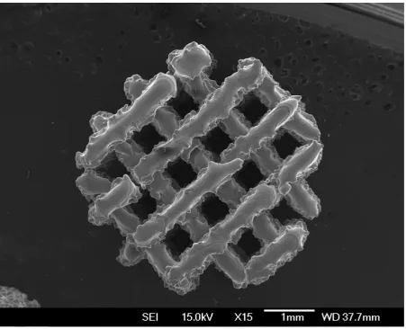
approach lumbar interbody fusion (ALIF) procedure. The implant was designed to be produced using electron beam melting and uses a simple cubic scaffold intended to encourage bone ingrowth into the device. ... 42 Figure 5: A porous lattice structure produced by controlling the raster spacing of an electron
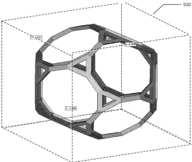
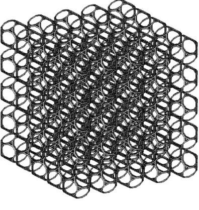
beam melting machine. Note the alternating direction of the ‘fibres’ in the top layer and layer below, similar to traditional FDM lattice structures. ... 45 Figure 6: The modified dodecahedral unit cell, as shown in Figure 5B of patent
US20130199748 A1 [118]. The unit cell is based on a dodecahedron with each vertex truncated such that each pentagon now forms a regular decagon and each vertex now forms an isolateral triangle. Note the choice of triangular struts that minimise the
number of total faces on the solid part. ... 48 Figure 7: The bulk structure resulting from the repeating unit cell, as shown in Figure 5E of
patent US20130199748 A1 [118]. The unit cell is repeated in orthogonal directions (x, y and z) and each unit cell abuts its neighbour along a one length of the decagonal faces of the unit cell. The specific pattern creates a range of pore sizes and open channels
running between the unit cells. ... 49 Figure 8: The electron beam melting process results in a characteristic rough as grown
surface. The spherical features are built powder that are fused to the part surface. ... 57 Figure 9: The rough as grown surface produced by the electron beam melting process is
uniformly present on the bottom and sides of scaffold struts. ... 58 Figure 10: The top surface of parts produced by electron beam melting is smooth, because
there is no free build powder above the working layer to fuse to the part. ... 59 Figure 11: Layering artefact is clearly seen in this part produced by electron beam melting.
Layering artefact occurs because the part is built in a series of discrete layers stacked on top of each other. The layers in this part were 70 µm thick. ... 60 Figure 12: Pronounced layering artefact on a single thin strut produced using electron beam
melting. The significant variation in strut thickness is due to the large size of the melt pool relative to the size of the feature. This strut is at the lower size limit of what can be reliably produced using electron beam melting. ... 61 Figure 13: Macroscopically smooth surfaces can occur where loose powder has removed by
blasting. At high magnification, this surface shows evidence of ductile rupture of the loosely adhered build powder. ... 62 Figure 14: A set of instruments was designed and manufactured to assist with the surgery. In
order from the top: mallet, punch, inserter, and drill guide. The inserter instrument has recessed cylindrical tip with a leaf spring retainer to accommodate and securely hold the dowel implant during positioning and introduction into the drill hole defect. Final
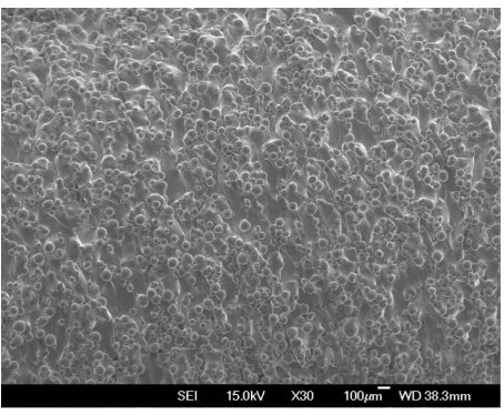
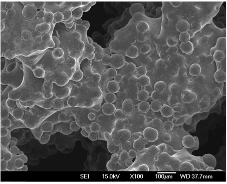
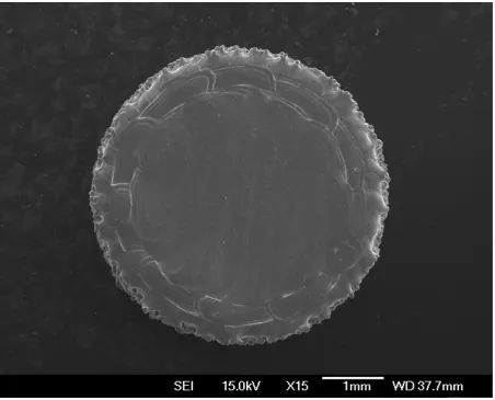
Figure 15: An overview of the samples used in the in vivo trial, shown at various magnifications using SEM. The rough as grown surface characteristic to the EBM process is uniformly present on all surfaces. ... 103 Figure 16: Implant locations. The skeletal anatomy of the sheep (left) with the tibia identified
by a black square. The enlarged region (right) shows the approximate locations of the five surgical sites, two sites in the anteromedial tibial epiphysis and three sites in the anteromedial tibial diaphysis. These locations were chosen to maximise the number of samples that could be placed into each animal while maintaining the structural integrity of the tibia. A minimum separation of 20 mm was maintained between each defect in the diaphysis. Two defects were able to be placed in the proximal tibia, which was a simpler surgical approach than the distal femur as it did not disrupt the joint capsule. Note that procedure is performed bilaterally (on both legs), but that the approach is from the medial side so surgical sites in the left tibia in the foreground are hidden. ... 105 Figure 17: The hind legs and rump were clipped and cleaned outside of the operating theatre
to minimise the transfer of dirt on the woolly covering of the animal. At this stage, the sheep had already received a premedication including antibiotics, which reduces the opportunity for infection caused by micro abrasions sustained during clipping. ... 109 Figure 18: Following clipping, the hooves and canon were covered with a latex glove and
cohesive bandages. This created an impervious barrier that isolated the dirty region from the surgical field. Note, this is prior to the application of another layer of sterile cohesive bandages during draping, which creates an aseptic covering. ... 110 Figure 19: An epidural regional analgesia was administered prior to surgery. This technique
blocks the transmission of pain signals through nerves in the cauda equina. This proceedure was performed with aspetic technique using sterile gloves and the region cleaned with chloroxeidine and alcohol. Note the air bubble in the syringe that is used to visualise the lack of resistance to the injection confirming the needle is in the epidural space. ... 111 Figure 20: The animal was positioned in dorsal recumbence and supported by lateral chocks
and tie down restraints. Final cleaning and preparaton of an aseptic surgical site was performed using aquous chloroxidine scrub and alcohol because the animal was housed on a farm and physical debris had to be washed from the wool. Note the cohesive bandages on the hooves that minimises the transfer of dirt to the gloved hands of the surgical team. ... 112 Figure 21: A thermal blanket, heat pad (only the cord is visible) and insulating towels were
used to maintain body temperature during surgery. Maintaining body temperature prevents unintended perioperative hypothermia, a common occurrence in an un-warmed patient that is associated with significant morbidity or even mortality. ... 113 Figure 22: An incision is made in the anteromedial tibial epiphysis. A single incision is made
down to the bone because there is very little soft tissue in this region. Note the needle used to identify the joint space proximal to the incision. Full aspetic technique is used to reduce the risk of infection. ... 114 Figure 23: The incision is retracted using a mini Gelpi retractor and the periosteium scraped
back using a periosteal elevator. Note there is minimal bleeding because retraction aids in hemostasis and the choice of surgical site is free of major blood vessels. ... 115 Figure 24: The bone surface is exposed and a second pair of mini Gelpi retractors is used to
maintain a small (10 mm) window. The remainder of the implant procedure is
performed through this small incision. ... 116 Figure 25: The defect is introduced by drilling at low speed. A domestic battery-operated drill
use of saline lavage to prevent heat build-up and flush debris from the surgical site. The surgical drapes include an impervious layer to prevent strike through caused by the lavage. ... 117 Figure 26: The surgical defect is flushed of debris using copious saline lavage. The tightly
controlled defect geometry creates a reliable press-fit for the implant. ... 118 Figure 27: The implant is aligned with the defect and a custom punch and mallet is used to
lightly impact the implant into its final location. The animal’s leg is supported by the arrangement of the lateral chocks and an assistant during this stage. ... 119 Figure 28: The implant in situ in the proximal tibia. Note the implant is flush with the
superficial surface of bone. The implant is held in place by press-fit and no additional support is required to prevent implant migration. ... 120 Figure 29: The incision is closed in two layers. The periosteum and sub cutis is closed using
absorbable sutures and the cutis is closed using non-absorbable sutures. The suture was finished with an Aberdeen knot. ... 121 Figure 30: Surgical sites were sequentially exposed from proximal to distal. Here, the second
cortico-cancellous site has been exposed in the anteromedial tibial epiphysis. Note the copious lavage has spread liquid around the surgical field. Lavage dilutes the incision site and reduces the risk of infection, but as seen here, necessitates an impervious drape to prevent strike through from the patient outside of the sterile field. ... 122 Figure 31: This finished result. Five individual surgical sites in the anteromedial tibia of the
sheep. Each incision is approximately 10 mm in length. Note that surgical sites in the diaphysis are separated by 20 mm each to reduce the risk of fracture. The leg has been swabbed down with saline, but the incision sites have been left untouched to reduce the risk of infection. The skin is swollen partially due to the subcutaneous administration of long-lasting local anaesthetic. ... 123 Figure 32: After surgery, a sterile non-adherent dressing is applied to the surgical site. A
Robert Jones bandage [151] consisting of Gamgee tissue covered with cohesive bandages is applied prior to the patient leaving the surgical theatre. The bandages help reduce swelling and provide a temporary barrier to infection while the skin heals. The bandages were removed after 48 hours. ... 124 Figure 33: The animals recovered quickly and were bright and alert after approximately 15
minutes following the withdrawl of gaseous anasthesia. The animal above was enjoying some chaf, in spite of the affects the anasthesia still lingering, a good sign following surgery. The value of the bandages can also be seen as the bandages are already soiled from contact with the holding pen. ... 125 Figure 34: Local hypertrophy and scar tissue cohesion are clearly visible on dissection at 3
weeks post-surgery. Tissue was dissected in layers to expose the bone. The tibia was harvested intact and frozen in saline. Subsequent resection of individual implants and bone biopsies were performed with the sample frozen. This approach minimised the effects of autolysis. ... 126 Figure 35: Sample mounted on a removable platen immediately prior to testing in a push-out
rig. The implant is aligned concentric with a clearance hole in the removable platen and dislodged from the bone during compression displacement. ... 131 Figure 36: Failure mode analysis of the bone to implant interface immediately after push-out
testing. Intact sample with implant dislodged (left) and magnified, showing shearing of the bone to implant interface (right). ... 135 Figure 37: Gross sectioning of the proximal tibia prior to fixation. Each implant was retrieved individually with the surrounding bone intact, but soft tissue carefully removed. ... 144 Figure 38: Biopsies were trimmed to a uniform size to enable consistent processing in
Figure 39: The location and orientation of the histological sections is shown inset and enlarged, next to the entire tibia. The two implants in the proximal tibia were processed for histology and only the mid-line section of the implant was used for
histomorphometric analysis. Adjacent sections were used for staining optimisation. .. 148 Figure 40: An example of a large composite image of a full histological section stitched
together from 68 individual microphotographs taken at x10 magnification. The resulting image was reoriented to aid in the positioning of an ROI for histomorphometric analysis. The position of the ROI is shown here with a red box. ... 150 Figure 41: An example of an ROI positioned coincident with the margins of implant cylinder
and so as to exclude both superficial and deep bony overgrowth. A standardised 2 mm high by 5 mm wide ROI was used for histomorphometric analysis of bone ingrowth and bone to implant contact across samples. ... 151 Figure 42: An example of methylene blue and basic fuchsin stained sheep bone. (Top)
Unstained ground resin section of a 3D printed titanium scaffold implant in situ in sheep bone. (Middle) Adjacent section stained with methylene blue and basic fuchsin.
(Bottom) The top section stained with Goldner’s trichrome stain. ... 154 Figure 43: An example of von Kossa stained sheep bone. (Top) Unstained ground resin
section of a 3D printed titanium scaffold implant in situ in sheep bone. (Middle) Adjacent section stained with von Kossa stain. (Bottom) The top section stained with Goldner’s trichrome stain. ... 155 Figure 44: An example of an unstained ground resin section of a 3D printed titanium scaffold
implant in situ in sheep bone. The implant is clearly discernible in black, but the
surrounding bone and soft tissue lacks specificity. ... 156 Figure 45: An example of Goldner’s trichrome stained ground resin section of a 3D printed
titanium scaffold implant in situ in sheep bone. The implant is clearly discernible in black, mineralised bone in green, and actively mineralising osteoid in red. ... 157 Figure 46: Histological section thickness had a marked effect on staining. (Top) Fluctuation
in thickness across a nominal 27 µm thick section resulted in variation in staining colour across the sample. (Middle) A nominal 50 µm thick section resulted in the best overall staining colouration and consistency, and was used for all subsequent sections. (Bottom) A nominal 100 µm thick section was too opaque to adequately highlight histological features. ... 158 Figure 47: An overview of bone ingrowth and bone to implant contact for 3D printed
titanium scaffold and monolithic implants after 3, 6 and 12 weeks in situ in a sheep drill hole model. Bone ingrowth increased with time for all scaffold samples and completely filled the porous space by 12 weeks after surgery. Direct bone to implant contact was evident for all samples. ... 159 Figure 48: An overview of bone remodelling in and around 3D printed titanium scaffold and
1 Introduction
1.1 Overview
Joint disease is the leading chronic condition in the elderly and affects almost half the population over the age of 65 [1]. Unfortunately, as our population demographics grey and grow older this condition will negatively affect the quality of life of more individuals each and every day. However, the good news is that surgical interventions for arthritic, destructive and necrotic joints and joint surfaces can reduce the pain associated with daily living and are the most effective health care measures for improving patient quality of life [2].
Uncemented prostheses do not use bone cement for fixation and instead rely on a direct interface between the implant and surrounding bone to achieve long-term implant survival. Though current joint replacement prosthetics have an ultimately limited life, there is a great deal of momentum in the development and uptake of uncemented prostheses that may greatly extend implant lifecycle. Advances in uncemented prosthetic technology, particularly for challenging revision arthroplasty, require the pioneering of new, more effective solutions. The development and validation of one such new interface forms the underlying premise of this thesis.
the device within healthy, living bone. This thriving environment helps to avoid the otherwise inevitable decline caused by stress shielding, where the bone becomes weak, embrittled and receding as a result of a stiff prostheses failing to expose the adjacent bone to sufficient strain to maintain bone health [5]. This decline ultimately requires removal of the implant from host bone through destructive revision surgery [6]. It is this single mechanism of failure that is largely responsible for the need to improve the long-term clinical outcomes of uncemented implants.
Recent methods of improving the osseointegration of prostheses, such as for total hip and total knee replacements, are focused on the combination of porous scaffold structures with rough surfaces that together facilitate direct bone apposition and mechanical interlocking of bone at both cellular and tissue levels. The utilization of additive manufacturing has allowed unprecedented advances in the creation of these interfaces by enabling their direct manufacture and incorporation into medical devices [7]. This direct printing of integral scaffolds and underlying structural features has notably overcome the specific issue of coating delamination that has plagued uncemented prostheses in the past [8]–[11]. As the integrated nature of these bone interfaces is intrinsically more robust than previous sintered coatings, the medical device community has been emboldened to try scaffold structures with large pore sizes and high porosities. The movement towards macro scaled pore sizes, over previously used micro scale porous surfaces, is intended to enable significant improvements in osseointegration.
implants that greatly increase the quality of life of sufferers of joint disease in our ever-ageing population.
1.2 Background
1.2.1 Titanium in Orthopaedics
Although the use of titanium in orthopaedic implants dates back to the 1950’s, it was only after Brånemark discovered what he termed the osseointegration phenomenon in 1964 [14] that the exploration of this material’s dental and surgical applications exploded into the limelight. Over the decades that followed, a plethora of research firmly established titanium as the ’gold standard’ biomaterial for bone interfacing and load bearing orthopaedic devices [15]. Today, titanium and its alloys are the ubiquitous metallic biomaterials and form the foundation from which the goal of improved osseointegration is pursued.
In its pure form, titanium exhibits many favourable properties for use in orthopaedic devices. When combined, with small fractions of aluminium and vanadium, the resulting alloy possesses excellent mechanical properties including high strength, a moderate bulk modulus and a relatively low density [16]. This alloy has the additional benefit of significantly reduced thermal conductivity that, perhaps non-obviously, has a pronounced influence on patient comfort, especially in colder environments. However, more importantly, titanium and its alloys are bio-inert [17] and have excellent corrosion resistance in the human body due to the formation of a protective oxide layer. Titanium is thus biocompatible [15] and, in an optimal situation, capable of osseointegrating with bone [18].
structured CP Ti is typically used in dental and maxillofacial implants and the harder, high strength biphasic α + β micro structured Ti-6Al-4V reserved for use in load bearing orthopaedic applications [19]. The inclusion of aluminium and vanadium alloying agents help to stabilize the biphasic microstructure with the β stabilizer (V) giving Ti-6Al-4V the ability to be solution treated to achieve even higher strength when required.
Despite wide spread use, some concerns have been raised about the long-term effects of cytotoxic alloying elements, including vanadium [17], [20]. The release of cytotoxic elements affects not only surrounding tissue, but the body as a whole. Both aluminium and vanadium ions have been associated with long term health problems like Alzheimer’s disease and neuropathy [21], [22]. To address these issues, new titanium alloys that make use of potentially less harmful elements are being developed [15], [23].
Of particular interest are the second generation of β metastable titanium alloys without cytotoxic alloying agents. Specifically, Ti-12Mo-6Zr-2Fe (TMZF) and Ti-Nb-Zr-Ta (TNZT), which exhibit significantly reduced moduli compared with Ti-6Al-4V. As these materials mature, they will no doubt play an important role in the continued prevalence of titanium in biomedical applications.
1.2.2 Stress Shielding
to the adjacent remodelling bone may result in bone mineral resorption and eventual loosening of the device [25]–[28]. Alarmingly, it has been clearly demonstrated that when the natural loads on living bone are reduced, bone thickness is decreased, bone mass is lost, and there is an increase in osteoporosis [28]–[30]. This outcome can contribute to catastrophic failure of the implant system, as a significant reduction in the patient’s bone density may have been a factor in the need for the original treatment.
1.2.3 Porosity and Bone Ingrowth
Porosity is the amount void space in a material and allows it to be infiltrated by bone. The introduction of porosity to the surface of an implanted device has the ability to further improve the bond between the device and the host. A porous surface can facilitate mechanically interlocking bone ingrowth that considerably enhances the bone to implant interface strength compared with direct bone apposition alone. Practical application of this concept is used on the majority of devices on the market today.
1.2.4 Bone Tissue Scaffolds
Recently, there has been a paradigm shift to include porosity not only as a surface coating intended to improve bone to implant interface strength, but to transform a biomaterial into a bone tissue scaffold. These scaffold structures are being designed to carry physiological loads as well as allow for cell adhesion, proliferation and differentiation to form a healthy repair that restores functionality to the recipient site [35]. This level of interaction with the human body is far beyond that of traditional orthopaedic devices.
Successful bone tissue scaffolds must carefully consider pore size and porosity, fluid transport, material and device moduli, the behaviour of the material in the human body, and factors on the cell scale. Properties such as topography [36], [37] and chemical composition [38], surface energy [36], wettability, surface bioactivity, and even electrostatics [39], are now all becoming important considerations in bone tissue scaffold design. Hence, the problem has become more complex and considers a far greater number of design parameters.
1.2.5 Material Characterization
evolving material properties versus any specification. Contemporary methods that use advanced industrial computed tomography data as their basis are being adopted and, although refinement is needed, precedence for their use is established [45]–[47].
1.2.6 Manufacturing
Traditionally, three dimensional scaffolds and porous coatings for bone tissue engineering have been manufactured using gas injection [48], sintered powders [49] or fibres [50], [51], as metal foams [52], [53] using a space holder method [54], as vapour deposited constructions [43], or by using a plasma spray [55]. These methods create stochastically distributed pore sizes that may, in practice, extend far above and below the desired pore size range. The potential limitations of these methods are abundant, but none are more important than the constraint of maximum attainable porosities of less than 50% at desirable pore sizes [52], [56]. Such low porosities can drastically limit bone ingrowth and thus osseointegration, and are thus a hard limit.
One manufacturing technology, electron beam melting, is a qualified additive manufacturing method for medical devices [65]. This process involves the layer-by-layer melting of metallic powders with a high-energy electron beam. As these charged particles are deflected by a series of magnetic fields, there are no moving parts involved in the melting of each successive layer. This approach allows the rapid scanning of the energy beam across the build platform and results in a swift fabrication time.
The rough surface topography created by electron beam melting is a significant coincidence in to the success of additive manufactured orthopaedic implants. The energy imparted by the electron beam completely melts the targeted metal powder and creates an intrinsically micro-featured surface of partially coalesced powder on the periphery of the part. These rough implant surfaces increase bone to implant contact and interface strength and thus, an unintended side effect of this unfinished finish is an improved interface connection [66].
1.2.7 Pre-clinical Studies
Additive manufactured orthopaedic devices using Ti-6Al-4V as a bone tissue scaffold are leading endo-prostheses into the future. Pre-clinical studies are beginning to demonstrate the significant potential of additive manufactured titanium scaffolds [64], [67], [76]–[78], [68]– [75]. However, to date, the understanding of the mechanisms of their success is limited.
[86], [69], [74], [75], [77], [79]–[82]. Even so, the groundwork has begun to characterize simple constructions for use in bone interfacing devices [44], [70] and the mechanical properties of simple scaffolds have been evaluated [87]–[90]. Studies investigating bone ingrowth in additive manufactured Ti scaffolds have been performed [64], [68], [72], [74], [75], [77], [78] as well as studies of similar materials and structures, such as tantalum [43], Ti fibre scaffolds [69], and carbon fibre scaffolds [91], all of which demonstrate the potential of these biomaterials.
Spurred by early anecdotal successes, a number of increasingly clinically relevant studies are being undertaken on additive manufactured materials [70]–[73], [76]. In contrast to smaller animal models, such as the New Zealand white rabbit, the ovine (sheep) model has been validated for assessing the bone ingrowth in to these orthopaedic biomaterials and has suitable osseous structures that can closely model human anatomy [70]–[72], [92]–[95]. These contemporary studies using this more relevant model are rapidly expanding the knowledge base for additive manufactured scaffolds and will likely contribute to significant advances in the efficacy of orthopaedic devices in the years to come.
1.2.8 Evaluating Bone Ingrowth
straightforward to measure the extent of bone ingrowth and bone to implant contact. This technique of histomorphometric assessment remains the most trusted method to investigate the interaction of an implant and host bone, and is a key feature of this work.
In contrast with routine histology, the preparation of bone biopsies with in-situ implants is fraught with difficulty. Hard methacrylate embedding resin has to be used to plastify and support the biopsy to enable the implant to be sectioned without damaging the surrounding tissue. Diamond wafering tools, more commonly found in the semi-conductor industry, are employed as they impart little cutting force on the sample and only tenths of a millimetre of the precious biopsy are lost with each cut. After microscopically thin sections are prepared, special staining techniques are applied to dye cells and intercellular matrix features so they appear distinct under transmitted light. In this manner, the stage and structure of new bone growing into a scaffold can be clearly identified.
Non-destructive methods of evaluating bone ingrowth use instead the transmission and absorption of X-ray radiation to identify densely calcified regions of bone. Micro computed tomography (µCT), similar to its clinical counterpart, is able to create a true volumetric representation of a biopsy. This imaging technology is able to identify the X-ray attenuation of incredibly small regions of the sample, commonly at spatial resolutions of only few cubic micrometres. This high-resolution three-dimensional imaging can allow for accurate measurements to be made that quantitatively assess bone volume, though imaging artefact remains an issue with this method [45], [96]–[98].
differing information across the captured X-ray spectra to reduce image noise and artefacts, a severe limitation of traditional µCT systems [100], [101]. The combination of these impressive features in a computed tomography unit is in early, but active, development. It is hoped that the eventual system will have the ability to elucidate histological information without destroying the biopsy. This would prove to be a pre-clinical research tool ideally suited to the study of bone ingrowth into metallic scaffolds.
1.2.9 Evaluating Interface Strength
Methods for measuring the interface strength of the implant to the surrounding bone have been well described with the push-out method common to the vast majority of pre-clinical efficacy studies [31], [32], [103], [104], [43], [66], [67], [70], [71], [92], [93], [102]. In these studies, an implant dowel is loaded axially until it is dislodged from the host bone. This simple technique allows a direct measurement of the interface shear stress and affords a standardized metric to compare differing scaffold products. As such, this tool provides researchers and clinicians with comparative data from a plethora of product data collected over the last half a century of orthopaedic research.
1.3 Summary
2 Problem Statement and Context
2.1 Introduction
Uncemented orthopaedic implants, such as the acetabular component of a total hip arthroplasty, typically incorporate a porous material that apposes bone and provides fixation via bone ingrowth. Examples of porous materials in clinical use include sintered particles [49]–[51], metal foams [52], [53], and additively manufactured scaffold structures [66], [69], [70]. All of these materials must conform to relevant regulatory requirements.
The five founding members (AU, CA, EU, JP and USA) of the World Health Organization (WHO) Global Harmonization Task Force (GHTF) on Medical Devices all share a similar function in regulating medical devices in their respective jurisdictions. Each member enacts their requirements to maintain the safety and effectiveness of medical devices used in its healthcare system. Guidelines are generally available to assist device manufacturers to create products likely to be approved for use. The most commonly used guidelines are those published by the United States Food and Drug Administration (FDA) as they govern devices sold into the USA, the world’s single largest market for medical devices. Specific guidelines [105], [106] are available for porous materials and provide required considerations and ranges in values for various parameters found to be important over many decades of clinical experience.
This chapter describes the specifications of a new, additively manufactured scaffold based porous material for use in uncemented orthopaedic implants. First and foremost, the basic specifications are drawn based on relevant regulatory requirements. Additional factors are then described with the intention that, In Toto, the design specifications will lead to both a clinically and commercially relevant product.
2.2 Regulatory Requirements
Medical devices sold in the USA are governed by the FDA. The FDA publishes guidelines on a wide variety of topics with the intention of assisting medical device manufacturers to create safe and effective products. The relevant guidance document for designing the new porous material is: ‘Guidance Document for Testing Orthopaedic Implants with Modified Metallic Surfaces Apposing Bone or Bone Cement’ [105]. Additional guidance can be found in: ‘Class II Special Controls Guidance Document: Knee Joint Patellofemorotibial and Femorotibial Metal/Polymer Porous-Coated Uncemented Prostheses; Guidance for Industry and FDA’ [106].
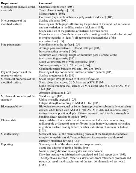
Table 1: Regulatory requirements for bone tissue scaffolds
Requirement Comment
Metallurgical analysis of the materials:
Chemical composition [105]; Trace element analysis [105]; Microstructure [105];
Corrosion (equal or less than a legally marketed device) [105]; Microstructure of the
modified surface:
Surface thickness [105];
Drawings or photographs illustrating the position of the modified surface(s) and any variation in modified surface thickness [105];
Shape and size of the particles or material between pores;
Diameter or area of welds between surface coating particles and substrate and microphotographs to identify all geometric characteristics of the
microstructure [105];
Pore parameters: Pore diameter at the surface [105];
Average pore size between 100 and 1000 µm [106]; Interconnecting porosity [106];
Minimum void intercept length or minimum pore diameter of the interconnecting porosity [105];
Mean volume percent of voids (porosity) [105]; Volume porosity of 30 to 70 percent [106];
Coating thickness between 500 and 1500 µm [106]; Physical properties of the
substrate surface:
Drawings of any non-random surface structure patterns [105]; Surface roughness in Ra [105];
Mechanical properties of the modified surface:
Shear fatigue strength tested to at least 107 cycles; Static shear shall exceed 20 MPa as per ASTM F 1044;
Static tensile strength shall exceed 20 MPa as per ASTM C 633 or ASTM F 1147 [105];
Abrasion simulation [105]; Mechanical properties of the
substrate:
Yield strength [105];
Ultimate tensile strength [105];
Fatigue strength according to ASTM F 1160 [105];
Biocompatability: Biological response equal or better than approved or substantially equivalent devices when tested with ASTM F 748, ASTM F 981, and an animal study testing tissue apposition, depth of tissue ingrowth, and interface strength in bending, shear, tension or torsion [105];
Clinical data: Any available clinical data that at minimum includes data on loosening, radiographic evidence of bone or fibrous tissue ingrowth, surface particulate migration, surface coating failure or other indications of success or failure [105];
Manufacturing: Sufficient detail of the manufacturing process of the final product and test samples to explain any differences between its properties and those of currently marketed devices [105];
Reporting: Summary table of the aforementioned requirements; Name and address of testing facility [105];
Name of study director, investigator and supervisors;
Date that testing was initiated and completed and final report date [105]; The objectives, methods, materials, deviations from references protocols and standards, results and conclusions of the test. (With mandated sections.) [105].
2.3 Clinical Performance
treatment options is paramount to maximise connection strength. There is a plethora of published information regarding aspects of porous material design [62], [107]–[110]. A thorough evaluation of this information should form the foundation of any new porous material design.
Porous materials have been in clinical use since the early 1940’s [111]. Using the best technology available at that time, sintered bead coatings, it was only possible to investigate basic relationships. A foundation study by Bobyn et al established that porosity at the surface of the implant can predict interface strength [31]. An early clinical report by Engh et al found that press-fit of the porous coated implant was important to successful bone ingrowth and that this led to stable fixation and excellent clinical results [112]. This result has recently been corroborated by Bertollo et al with a rigorous In Vivo investigation [71].
Decades of research followed these initial pioneering cases. Today, it is well-established that porous material design is a trade-off between large interconnected pores that permit nutrient and waste exchange, vascular intrusion and complex tissue formation, with the conflicting goal of mechanical integrity and tissue matched elastic moduli [62], [107]–[110].
Table 2: Clinical requirements for bone tissue scaffolds.
Requirement Comment
Pore size: Ideal pore size of 500 – 600 µm and minimum interconnecting pore size (throat size) greater than 200 µm [31], [33], [34], [36], [62]–[64], [106], [113], [114];
Pore interconnectivity: Fully interconnected pores, minimum pore interconnectivity value (Z) of 2 (single entry single exit, i.e. no dead-end pores), and pore interconnectivity value as high as possible (multiple entries and exits to every pore) [46], [97], [115];
Porosity: As high as possible (target 70 percent as regulatory guideline maximum) [31], [33], [114], [34], [36], [62]–[64], [105], [106], [113];
Surface roughness: High surface roughness (Ra) [66];
Press-fit: Surface is able to be placed in intimate contact with the surrounding bone i.e. no large layer thickness that dictates how a surface can be approximated [71]; Coefficient of friction: High coefficient of friction for initial implant stability [116].
2.4 Ancillary Requirements
A porous material will ultimately be used in a product that ends up in the hands of an orthopaedic surgeon. The design of a porous material can evoke great confidence in the product through perceived biological affinity and porous designs that mimic naturally occurring structures are generally well regarded in this respect [43], [76]. A design of porous material with visible biological potential that a surgeon can immediately engage with will be more easily adopted and this should be considered an essential design requirement.
The complex geometry of an orthopaedic implant must be considered when designing an aesthetic porous material. The material should present an equally advantageous surface when cut on a variety of planes. In this way, the contours of a patient’s bony anatomy can be followed with a uniform presentation of pores that bone may grow into.
The design for AM (DfAM) is an emerging sub-field in mechanical engineering that has evolved to take advantage of the new capabilities that the manufacturing platform offers. DfAM helps engineers both design parts that are efficient concerning cost, complexity and time, and seeks to avoid manufacturing defects caused by part geometry. For example, the consolidation of multiple components into one part for an integral porous coating on a hip replacement results in an implant that is stronger than with a traditional sintering process.
The electron beam melting process developed by Arcam (Arcam AB, Sweden) is an established choice for producing AM medical devices. This process uses a high-power electron beam (currently, up to 3 kW) to selectively melt a pre-heated titanium alloy powder to form a solid component. The design of the component must factor in the powder metallurgy underpinnings of this manufacturing technique, along with the large thermal stresses involved in selective melting. Additionally, the additive layer-by-layer approach introduces requirements for components to be supported against mechanical forces during fabrication, including gravity and those imparted by the machine’s blade that applies and smooths each successive layer of powder. Failure to address these design requirements may result in a component that has poor material properties, is warped or distorted, fails to fabricate successfully, or even damages the machine.
a human hip, the issue of computational weight is immediately apparent. The computationally light-weight design of the unit cell is now an obvious further requirement, which also interacts with porosity.
Following primary production, the porous material must be thoroughly cleaned of any manufacturing remnants. The removal of entrapped build powder is typically achieved in two stages. First, a closed loop blasting process scours loose powder from crevices and open porous channels and captures it for re-use in the building operation. Second, an ultrasonic bath filled with either super-clean water or isopropyl alcohol breaks apart clusters of compacted powder and encourages deeply trapped powder to escape through the porous material pathways, as possible. Following these initial, overall cleaning processes, products undergo critical cleaning to ensure they are suitable for implantation.
For any product to be commercially relevant, a proprietary right to control its manufacture and sale must be sought. Various mechanisms exist to garner this protection. Initially, a trade-secret approach that simply does not disclose critical aspects of the product may prove effective. In the longer term, and for greater security, critical aspects of the product should be patented. The basic requirements to patent are novelty and inventiveness. In simple terms, the design must not only be new, but must also be a non-obvious leap beyond the status quo.
Table 3: Ancillary requirements for bone tissue scaffolds
Requirement Comment
Aesthetics: Bio-mimetic design that evokes trabecular bone; Consistent when cut across multiple planes;
Manufacturability (computer design):
Lightweight STL file (less computationally intensive); Unit cell based;
Repeatable in orthogonal directions; Manufacturability (design
for AM):
Self-supporting structure;
No large overhanging features that are prone to distortion under gravity or by mechanical disturbance from the blade;
No large planar features that are prone to warping under thermal stress; Open porous channels to facilitate powder removal;
Manufacturability (primary manufacture):
Manufactured from titanium alloy grade 5 or 23, (Ti6Al5V or Ti6Al4V ELI); Additively manufactured using an Arcam S12 Electron Beam Melting (EBM) machine;
Manufacturability (cleaning):
Powder removal using Arcam powder recovery system; Powder removal and non-critical cleaning using ultrasonic bath; Patentable design: Novelty;
Inventive step.
2.5 Summary
Designing the structure of a material for use in a medical device is a complex task with competing requirements and multiple stakeholders. By breaking this task down into a series of discrete requirements it becomes obvious that many factors are prescribed. These factors are common between new and established designs alike. It is also clear that there is practically no limitation on the porous architecture, and, as a result, there is great opportunity to innovate here. Additive manufacturing provides the tools to build new porous designs that focus on improving biological interaction. These designs must encourage bone to grow into the porosity quickly and completely, thereby allowing the device to develop a robust and long lasting union with the patient.
2.6 Problem Statement
of the development of the novel material will be given including presentation and evaluation of selected concept materials against a subset of the design requirements. A comprehensive background and methods development process will be undertaken to determine a suitable animal model and bone to implant interface analysis techniques.
The primary aims are to: a) demonstrate efficacy, ideally over and above existing treatments; b) investigate the effect of different scaffold topologies; and c) investigate the effect of small changes in pore properties with identical topology. The majority of this thesis will be the evaluation of efficacy by way of an animal study.
3 Material Concepts
3.1 Introduction
As stated in Chapter 2.6, the material concepts presented in this chapter were developed outside of the scope of this thesis by various individuals and industry partners. As such, and due to proprietary issues, their development is not reported. The purpose of this chapter is to provide context and details of the concepts to build a foundation for the following chapters.
Medical Modeling Inc. (Golden, Colorado, USA) was founded by Andy Christensen with the idea that medical imaging studies should not only be used for diagnosis, but that they should drive clinical treatment. Medical imaging studies, such as CT or MRI scans, provide a series of medical images that enable clinicians and engineers to visualise medical anatomy in 3D. These 3D visualisations are a natural fit with 3D printing, which allows that data to be printed in a tactile medium to help surgeons better understand and treat disease. Medical Modeling Inc. is a pioneer of additive manufacturing and began working with Arcam EBM (Arcam AB, Sweden) technology shortly following the commercial release of the Arcam EBM S12 in 2002. For the first time, the Arcam technology allowed the additive manufacture of end use titanium orthopaedic implants [65].
Figure 3 shows the end result, the clinical application of one of the first 3D printed implants in New Zealand. This particular custom implant was co-designed by Paul Morrison and Seamus Tredinnick and treated a maxillofacial tumour resection.
Figure 3: The definitive maxillofacial implant in situ during reconstructive surgery. The implant was produced using electron beam melting and finished using traditional machining techniques. The bone interface was left as grown.
[image:41.595.73.524.71.305.2]Figure 4: CAD model of an implant to replace an inflamed spinal disc during an anterior approach lumbar interbody fusion (ALIF) procedure. The implant was designed to be produced using electron beam melting and uses a simple cubic scaffold intended to encourage bone ingrowth into the device.
To enable Enztec to focus on its highly successful surgical instrumentation business, the design and production of custom implant products was shifted to another business in 2008, Stratatec Ltd. (Christchurch, New Zealand, est. 1998), New Zealand’s first rapid prototyping bureau of which Paul Morrison was also a co-founder. Now focused on patient specific treatments for complex acetabular (hip) reconstructions, the products were sold under the trade-name ‘Ossis’. Under this brand, there was new found enthusiasm to ‘productify’ the scaffold used to create rapid cement free fixation, a critical foundation of the success of their products.
undertaking would provide Ossis with valuable data it could use to confidently market the bone ingrowth properties of its custom hip products. The desire to capture the science behind why these products work so well was the genesis of this research.
Ossis Ltd. and manufacturing partner Medical Modeling Inc. set out to develop a scaffold for use in Ossis’ custom hip products. Two candidates were put forward for inclusion in this project: 1) ‘Cranial Mesh’, an existing product developed in-house at Medical Modeling Ltd.; and 2) ‘Labrynth’, which was collaboratively developed by Andy Christensen, Ryan Kircher, Paul Morrison and Seamus Tredinnick. The two candidates were radically different in their design and manufacturing pathways.
The design for additive manufacturing (DfAM) of scaffold structures for production on the Arcam EBM S12 machine had to deal with the idiosyncrasies of the specific technology platform. In the mid-2000’s the desktop computing tools were simply not able to handle complex models of organic surfaces comprised of thousands or millions of faces. This issue is still somewhat of a limitation today, because, although the computational tools have improved, so too have user expectations.
The concepts presented herein tackle the challenges of DfAM using different approaches. Cranial Mesh was developed so the porous properties could be applied during the build processing step. This method circumvented the computational overheads associated with designing a complex structure using CAD tools. In contrast, Labrynth was designed to have a lightweight file size so that the structure could be easily manipulated on a CAD workstation.
Ossis Ltd. and Medical Modeling Inc. during the development of these products, and a summary is presented to allow the reader understand what makes these products unique, without disclosing proprietary information.
3.2 Cross Hatched Lattice (CH)
Figure 5: A porous lattice structure produced by controlling the raster spacing of an electron beam melting machine. Note the alternating direction of the ‘fibres’ in the top layer and layer below, similar to traditional FDM lattice structures.
Cranial Mesh (CH) was designed as an analogue of a porous cross-hatched lattice structure produced by FDM. As implemented here, the lattice structure is only applied during the build processing stage. This workflow is attractive because the original component model remains lightweight and able to be manipulated on a traditional workstation.
EBM is an AM process in which a high-energy electron beam selectively melts a bed of powder. The electron beam follows a predetermined beam path (raster) on each layer of the build. By controlling the beam current, and spacing and orientation of the raster, it is possible to produce parallel struts. By modifying the orientation of the raster, it is possible to build up a lattice structure over successive layers of the build.
CH is a cross hatched lattice structure. Parallel struts are spaced 1 mm apart and the orientation of the struts is alternated by 90 degrees every 1 mm in the Z axis. The width of the strut is determined by the electron beam melt pool. Cranial Mesh was originally developed by Medical Modeling Inc. for use in cranial flap prostheses, and was one of the first clinically applied porous structures produced on the EBM platform.
3.3 Modified Dodecahedron (D1 and D2)
In particular, natural trabecular bone is a complex array of struts that bound separation spaces (pores), which vary widely in size and shape. In natural bone, the distribution of these parameters is continuously variable. This complexity is difficult to replicate with common CAD tools.
Labrynth overcomes this complexity issue by simplifying the trabecular structure down to a unit cell. This unit cell is repeated in orthogonal directions to build up a bulk material. The size of the unit cell can be scaled appropriately to match the pore size of trabecular bone. In this case, each cell is 1.8 mm along each side.
The Labrynth structure has oblique struts built up layer-by-layer. The cross section of the struts presents a range of profiles to the build surface, ranging from circular, when the strut is aligned with the Z axis, through rectangular, when the strut is aligned with the X or Y axes. In these two different scenarios, the beam path ranges from very short stop/start paths through long continuous paths, respectively. When built using the Arcam EBM standard build parameters (theme), there is a significant difference in the as-built strut properties due to heat build-up effects.
To create uniform struts, a custom build theme was developed. The build theme remains a proprietary trade-secret of Arcam AB (Sweden). Traditional build themes use continuous beam paths of various beam currents and raster speeds. The Labrynth build theme instead uses discrete points to create overlapping circular melt pools. In this way, the size of the melt pool can be controlled more readily, allowing the Labrynth structure to be built with more uniform struts.
The Labrynth build theme creates melt pools at discrete uniformly spaced points. Because of this discrete step-wise build theme, small changes of the modelled strut diameter have no effect on the as-built strut diameter. Therefore, to change the strut size, the beam current settings can be modified to affect the melt pool diameter. Thus, higher beam current results in a larger melt pool and larger strut diameter.
D1 and D2 ensures that Ossis Ltd. (Christchurch, New Zealand) has design knowledge and options in the future.
The Labrynth structure and its production method was developed by Andy Christensen and Ryan Kircher (Medical Modeling, Colorado, USA) with input from Paul Morrison and Seamus Tredinnick (Enztec, Christchurch, New Zealand, and Ossis, Christchurch, New Zealand, prior to PhD commencing). Labrynth was subsequently patent in the USA by Medical Modeling Inc. (Golden, Colorado, USA) with Andy Christensen and Ryan Kircher as named inventors. Additional information can be found in patent US20130199748 A1 [118].
3.4 As Grown (AG)
The raw, as grown surface of an EBM fabricated part is very rough. Anecdotal clinical experience showed that a variety of tissues readily attached to this surface (P. J. Burn, personal communication). A monolithic, solid, non-porous, sample with the as grown surface (AG) was put forward for inclusion in this study. The AG sample was mooted as both an effective alternative surface finish for an implant, broadly equivalent to roughened surfaces such as course grit blasted or a plasma spray coated, and also to serve as an on-growth surface control sample.
3.5 Summary
4 Characterization
4.1 Introduction
This chapter details the characterization of the material concepts from Chapter 3 against the various specifications outlined in Chapter 2.2 – 2.4. Established characterization techniques were used wherever possible. Therefore, and by intent, many of the results presented in this chapter align with the regulatory guidelines for porous materials in orthopaedic devices [105], [106]. Additional techniques were employed as required to allow for a better, more detailed comparison of the samples.
Additively manufactured metals are not well established at the FDA. Traditional requirements for porous materials relate to coatings and address concerns with their interaction with the substrate, particularly regarding delamination of porous sintered bead coatings delaminating from solid substrates. In contrast, single step additive manufacturing techniques can produce components with integral porous and solid domains, negating issues of coating delamination. Hence, the majority of the characterization methods used herein focus attention on the properties of the porous structures, which is the primary, relevant concern.
Some FDA requirements were not addressed herein either because they were comprehensively and conclusively evaluated elsewhere, or because they were outside the scope of this study. Specifically, evaluation of the mechanical properties of the materials was not within the scope of this study. Primary biocompatibility studies were not undertaken as the response to implantation of Ti6Al4V has been well established in a wide variety of sites and species and the material is in common clinical use [15], [20], [23], [119], [120]. A pre-clinical efficacy study is the main focus of this thesis and will be presented in detail in the following chapters.
4.2 Metallurgical Analysis
The ultimate performance of an implant is significantly influenced by the properties of the bulk material. Titanium and titanium alloys have a long-established history as effective materials for constructing orthopaedic implants. Electron beam melted titanium is directly comparable to identical alloys produced by conventional methods.
Leading into this project, Christensen et al [65] investigated the metallurgic properties of Ti6Al4V produced via EBM. The chemical composition, microstructure and mechanical properties of bulk material (Ti6Al4V ELI) were evaluated to qualify this new production method for orthopaedic applications. In conclusion, Christensen et al [65] stated that “The results demonstrate that the EBM process is a manufacturing technique capable of meeting, and in some cases exceeding, the properties of present manufacturing methods.”.
standards meet identical requirements to existing material standards for conventional manufacturing methods. For example, the compositional requirements of ASTM F 2924 are identical to ASTM F1472, Ti6Al4V wrought alloy [123]. However, powder fusion processes can fully melt the material thereby creating a new microstructure and potentially contaminating the chemical composition. To address this significant concern, AM specific standards place additional emphasis on process control and metallurgic inspection within an appropriate quality management system, such as ISO 13485 for medical devices [124].
The bulk material used for all samples here aligns as a substantially equivalent material and meets the requirements of the FDA at the present time. It has been qualified for use by test to the specifications of existing comparable materials [65], [125], [126]. Furthermore, the material can meet the additional requirements outlined in ASTM F 2924 or ASTM F 3001, when produced within the scope of an ISO 13485 accreditation.
4.3 Physical Properties of the Substrate Surface
4.3.1 Surface analysis
4.3.2 Surface features
The surface of the as grown EBM samples were imaged using SEM. Samples were imaged using a Hitachi TM3000 Tabletop Microscope (Hitachi Ltd., Japan) at a range of low magnifications (x30, x50, x100 and x200). Images were acquired at similar locations on each sample in order to assess and compare surface topography. Interesting features were imaged at higher magnification using a JEOL JSM 6100 (JEOL Inc., USA).
Figure 10: The top surface of parts produced by electron beam melting is smooth, because there is no free build powder above the working layer to fuse to the part.
Figure 12: Pronounced layering artefact on a single thin strut produced using electron beam melting. The significant variation in strut thickness is due to the large size of the melt pool relative to the size of the feature. This strut is at the lower size limit of what can be reliably produced using electron beam melting.
Figure 13: Macroscopically smooth surfaces can occur where loose powder has removed by blasting. At high magnification, this surface shows evidence of ductile rupture of the loosely adhered build powder.
4.3.3 Surface roughness