Protection of Crack Generation by Functionally Graded Layer at the Interface
of Hard-facing Iron Alloys
*1Akio Kagawa
1, Yasuhira Ohta
2, Kazunori Nakayama
1;*2and Taketoshi Chifu
1;*31
Department of Materials Science and Engineering, Nagasaki University, Nagasaki 852-8521, Japan
2Technology Center of Nagasaki, Omura 856-0026, Japan
The protection of crack formation by a functionally graded layer at the interface of surface-hardened iron alloys has been investigated using a modified reactive diffusion process which consists of the two-stage diffusion heat-treatment for diffusion species. From the stress analysis on thermal shock test and the microstructure observation, it was known that cracks formed on the thermal shock test were onion cracks arising from a radial stressrand radial cracks due to a circumferential stress. In the specimens subjected to the modified reactive diffusion
heat-treatment, a functionally graded layer was formed at the interface between the surface carbide layer/iron substrate, which effectively suppressed the generation of cracks by shifting a location of the maximum tensile stress toward the substrate and relaxing a stress concentration at the interface.
(Received August 8, 2002; Accepted April 21, 2003)
Keywords: hard-facing, reactive diffusion, functionally graded layer, thermal shock test, stress analysis
1. Introduction
In the metal/ceramics bonding and the ceramics coating on metallic materials, a significant difference in thermal expansion between metals and ceramics causes thermal stress at the metal/ceramics interface which may result in a poor interface strength and interfacial cracking. Such an imperfect interface bonding leads to a reduction in mechanical proper-ties and the reliability of the products. Hitherto, many works on the reactive diffusion method for wear resistant surface modification have been reported, where a carbide forming element, such as chromium, titanium and vanadium, diffuses from the surface of a steel and reacts with carbon in the steel to form a carbide on the surface.1–3)However, the diffusivity of carbon is much greater than carbide forming elements in steels, and hence carbides formed on the surface have a clear interface with the substrate. On cooling from the process temperature to ambient one, a large thermal stress would be generated at the interface, possibly causing interfacial cracking. In a modified reactive diffusion process, consider-ing the difference in the diffusivity of diffusion species and employing an iron intermediate layer as a diffusion media, a carbide forming element diffuses in the iron intermediate layer to build a gently graded concentration profile during the first-stage heat-treatment performed at higher temperatures, and then a diffusion bonding process (the second-stage heat-treatment) is performed at lower temperatures where main diffusion species is carbon. A functionally graded (F.G.) distribution of a carbide is formed at the carbide/substrate interface by the ‘‘two-stage diffusion process’’ and such a F.G. layer is expected to suppress thermal stress generated at the surface coating/substrate interface in coated tools and dies suffered from a thermal cycle. In our earlier works,4–6) the two-stage diffusion process to built a F.G. distribution of
titanium, vanadium and chromium carbides at the carbide/ substrate interface has been proved to be effective to suppress interfacial cracking by diminish a stress concentration at the interface. However, the mechanism for the protection of cracking by the F.G. layer has not been clarified.
In the present work, the effect of F.G. layer on the formation of cracks in the surface chromium carbide layer of hard-facing iron alloys has been investigated on the basis of thermal shock test and stress analysis on quenching.
2. Experimental
The interface modification process with a F.G. layer introduced in the present work consists of the two-stage diffusion heat-treatment: the first-stage diffusion process where chromium diffuses in the iron intermediate layer and the second-stage diffusion bonding process where chromium in the iron intermediate layer reacts with carbon which diffuses from the steel substrate to form chromium carbide. In an earlier work,6)it has been suggested that there is a critical thickness of the F.G. layer to suppress the generation of cracks and that the control of the F.G. layer thickness is possible by choosing a suitable condition in the first-stage diffusion process, since the thickness of F.G. layer coincides with the diffusion distance of chromium in the first stage diffusion heat-treatment.
In the present work, the specimens with different thickness of the F.G. layer were prepared by changing the holding time in the first-stage diffusion heat-treatment. The sandwich specimens of pure iron foils with 150, 250 and 500mmthick coated with a chromium-plated layer with 90, 100 and 200mmthick, respectively, were set between the upper and lower tool steel rods in the vacuum furnace shown in Fig. 1a. The load applied on the specimen was 30 N, the sum of the tool steel rod and the weight. The first-stage diffusion heat-treatment was carried out under argon gas atmosphere at 1273 K for 3.6–18 ks followed by furnace-cooling (Fig. 1b). The second-stage heat-treatment for carbon diffusion and diffusion bonding of the first-stage sandwich specimens with *1This Paper was Originally Published in J. Japan Society for Heat
Treatment42(2002) 184–189. *2Graduate Student, Nagasaki University,
Present address: c/o Tsubakimoto Chain Co. LTD. *3Graduate Student, Nagasaki University.
a tool steel 3 mm thick was performed at the same temper-ature for 3.6 ks followed by furnace cooling. For comparison, a sandwich specimen, Cr-plated iron foil/SK3 tool steel (t¼3mm) and Cr-plated SK3 tool steel (t¼3mm) speci-men were subjected to the heat-treatspeci-ment at 1273 K for 7.2 ks, as shown in Fig. 1c (Simultaneous D.B. specimen) and Fig. 1d (Direct D.B. specimen), respectively.
Thermal shock test was performed to examine the effect of F.G. layer to suppress cracking. After holding 0.6 ks at 1273 K, the three kinds of specimens subjected to the two-stage D.B., Simultaneous D.B. and Direct D.B. heat-treat-ment were quenched into iced water. The microstructures on the vertical section and in the surface carbide layer were examined by optical microscope observation. The stress analysis during quenching was carried out using a finite element commercial program MARC.
3. Results and Discussion
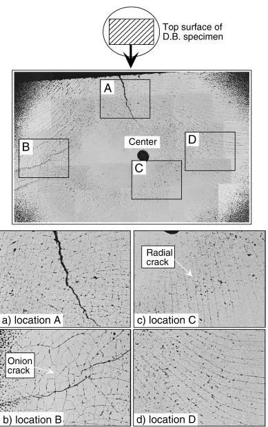
Microstructures on the section of the specimens subjected to direct D.B., simultaneous D.B. and two-stage D.B. heat-treatments are shown in Fig. 2. In the two-stage D.B. specimens, F.G. layers about 15mmthick (Fig. 2c) and about 50mm thick (Fig. 2d) are observed inside the surface chromium carbide layers 15–20mm thick. A thinner F.G. layer about 5mm thick is formed in the simultaneous D.B. specimen and no F.G. layer is seen in the direct D.B. specimen. Many cracks shown by arrows are observed in the direct D.B. specimen, while the number of cracks is significantly reduced in the specimens with F.G. layer, especially in the two-stage D.B. specimens having a wider F.G. layer. The microstructure on the horizontal section of the surface chromium layer is shown for the direct D.B. specimen in Fig. 3. It is known that cracks formed on the
SK3 Cr plating Cr plating
Fe foil
SK3 Cr-Fe
1st stage
b) two stage D.B. 2nd stage
SK3
Cr plating Fe foil
c) Simultaneous D.B.
d) Direct D.B.
Ar gas inlet
Thermo
-couple Ar gas
outlet O- ring
Weight
Pressure gauge
Tungsten mesh heater
Steel rod Specimen
a) High temperature vacuum furnace
Fig. 1 Experimental apparatus for diffusion heat-treatment and sandwich specimens for various diffusion bonding (D.B.) heat-treatments.
Fig. 2 Microstructures on the vertical sections of the specimens subjected to thermal shock test. a) Direct Bonding H.T.: 1273 K for 2 h b) Simultaneous H.T.: 1273 K for 2 h c) Two-stage H.T.: (I) 1273 K for 0.25 h + (II) 1273 K for 1 h d) Two-stage H.T.: (I) 1273 K for 1 h + (II) 1273 K for 1 h.
[image:2.595.100.497.72.349.2] [image:2.595.318.535.399.726.2]thermal shock test are radial cracks and onion ones. From the morphology of the cracks, it is suggested that the radial cracks are generated by a circumferential tensile stressand the onion cracks by a radial tensile stressr. To elucidate the effect of F.G. layer to suppress a crack generation, stress analysis was performed using meshed elements given in
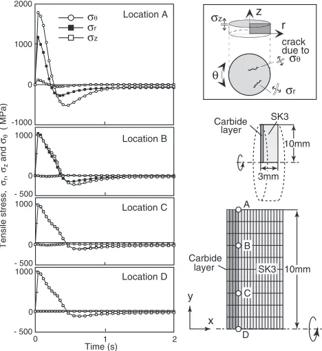
[image:3.595.106.495.64.683.2]along the circumferenceand along the thickness direction z on the edge of the surface carbide layer (A to D), as a function of time. A large tensile stress is generated just after quenching into iced water and then reverses to compressive stress. Since the stresszis negligibly small compared tor and, it is suggested that cracks generated on thermal shock test are radial cracks caused by thestress and onion cracks by ther stress. A large maximumstress generated at the edge of the carbide/substrate interface decreases rapidly
from the edge (Location A) to Location B!Location C!
[image:4.595.46.550.84.267.2]the center (Location D) where thestress is equal to ther stress. On the other hand, the variation of r stress is relatively small and r distributes homogeneously on the interface. It is, therefore, indicated that radial cracks tend to form near the circumferential edge on the interface and onion cracks on the whole area of the interface. From the results of stess analysis, cracks observed in Fig. 3 are considered to be initially generated at the interface under these stresses and grow through the carbide layer toward its surface. Figure 6 shows the influence of the thickness of F.G. layer on the stress distribution at the time of 0.09 s after quenching where the maximum tensile stress is generated on thermal shock test. In the case of the specimen without F.G. layer compared to those with F.G. layer, a large stress concentration exists at Table 1 Materials’ properties used for the stress analysis.
M7C3 80M7C3-20SK3 60M7C3-40SK3 40M7C3-60SK3 20M7C3-80SK3 SK3
Young’s modulus
230000 218000 206000 194000 182000 170000
(MPa)
Poisson’s ratio 0.22 0.228 0.236 0.244 0.252 0.6
Density
6.8 6.96 7.12 7.28 7.44 7.6
(g/cm3)
Thermal exp. coef. (/K)
1:0105 1:110
5 1:2105 1:3105 1:4105 1:5105 (upper:T>473K,
1:38105 3:76105 6:14105 8:52105 10:9105 lower:T<453K˙ )
Thermal cond.
20.9 23.4 25.9 28.5 31.0 33.5
(W/mK)
Specific heat
62.8 61.9 61.1 60.2 59.4 58.6
(J/gK) estimated SK3 Carbide layer F.G.layer 5µm
1mm
80-20 60-40 40-60 20-80
10mm
x y
Thermal shock test specimen SK3 Carbide layer F.G.layer 10mm 3mm 100%Carbide 100%SK3
Fig. 4 Meshed elements for stress analysis on thermal shock test.
y x Carbide layer 10mm 10mm Carbide layer SK3 3mm σz θ z r crack due to σθ σr 1000 0 1000 0 - 500 - 500 Time (s) 1000 0 1 2 0 - 500 SK3 σz σθ σr 2000 1000 0 -1000 Location A Location B C B Location C Location D A D Tensile stress, σr ,
σz and σθ
( MPa)
Fig. 5 Variations of tensile stress, r, and z generated at various locations on the interface between carbide and SK3 steel with time.
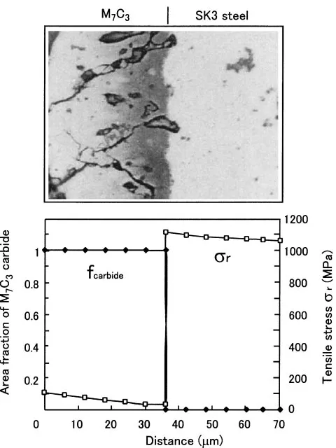
[image:4.595.50.289.291.641.2] [image:4.595.310.544.307.562.2]the sharp interface between the carbide layer and the steel substrate. The maximum stress reduces gently and the position of the maximum stress shifts toward the substrate with increasing the thickness of F.G. layer. This indicates that cracks observed in the direct D.B. specimen should be caused by a stress concentration at the sharp and uneven interface and that the F.G. layer in the two-stage D.B. specimens suppresses cracking by shifting a large tensile stress to the interface between F.G. layer/iron intermediate layer where a ductile iron matrix reduces the stress generated by plastic deformation. The ductile nature of the F.G. layer decreases with increasing the fraction of brittle carbide,i.e., approach-ing the carbide/F.G. layer interface. Figure 7 shows the distribution of area fraction of M7C3 carbide and tensile stress distribution ofron the section of the two-stage D.B. specimen having a F.G. layer 50mmthick. Carbide network (skeleton structure) is formed in the F.G. layer more than the carbide area fractionfcarbide(considered to be nearly equal to the volume fraction) of 0.5 where ductility may rapidly reduced.4) The r value at the location of fcarbide¼0:5 amounts to about 500 MPa which is nearly half of the maximum stress (1000MPa) generated at the interface between F.G. layer/iron intermediate layer. A deflective strength of TiC–Ni cermet is 1200–1800 MPa7)and that of TiC carbide may be a similar order. The strength of M7C3 carbide is roughly estimated to be of the order of 1000 MPa which is much higher than the r stress less than 500 MPa generated at the locations wherefcarbideis greater than 0.5. In such a condition, crack formation may be extensively suppressed. On the other hand, in the direct D.B. specimen shown in Fig. 8, the maximum tensile stress is generated in the substrate adjacent to the well-defined and uneven carbide/substrate interface. Such a stress concentration promotes crack formation.
4. Conclusions
From the stress analysis on thermal shock test and the microstructure observation, it was known that cracks formed on thermal shock test were onion cracks arising from a radial
Fig. 7 Distribution of M7C3carbide and tensile stressrin the specimen subjected to the two-stage diffusion heat-treatment.
Fig. 8 Distribution of M7C3carbide and tensile stressrin the specimen subjected to the direct diffusion heat-treatment.
1200
1000
800
600
400
200
0 100 200 300 400 500 Distance (µm)
r
z Carcide
225µm
110µm
55µm F.G.layer
without F.G.layer
Tensile stress,
σr
(MPa)
Carbide F.G.Layer Fe interm.Layer
[image:5.595.309.548.70.365.2] [image:5.595.55.282.74.252.2] [image:5.595.308.548.425.745.2]stressrand radial cracks due to a circumferential stress. The functionally graded layer in the specimens subjected to the two-stage diffusion heat-treatment effectively suppresses a generation of cracks by shifting the maximum tensile stress generated during the thermal shock test toward the ductile substrate and relaxing a stress concentration through plastic deformation of the ductile phase.
REFERENCES
1) O. Schaaber: Harterei-Techn. Mitt.4(1965) 238.
2) T. Arai, H. Fujita, M. Mizutani and N. Komatsu: J. Japan Inst. Metals
40(1976) 925–932.
3) Ge. Ve. Zemskov and El. eli. Cogan:Coupled Diffusion Method for
Metallic Materials, (Nisso Tsusinsya, Tokyo, 1982) p. 96. (in Japanese)
4) Y. Ohta and A. Kagawa: Netsusyori35(1995) 166.
5) A. Kagawa and Y. Ohta: Imono66(1995) 265. 6) Y. Ohta and A. Kagawa: Netsusyori38(1998) 334.
7) Nippon Kinzoku Gakkai edn.:Metals Data Book, (Maruzen, Tokyo, 1984) p. 116, p. 137, p. 138. (in Japanese)
8) Nippon Kikai Gakkai edn.: Elastic Modulus of Metallic Materials, (Maruzen, Tokyo, 1991) p. 68. (in Japanese)
9) Y. S. Touloukian, R. K. Kirby, R. E. Taylor and P. D. Desai:Thermal
Expansion, Thermophysical Properties of Matter, The JPRC Data
Series, (IFI Plenum, NewYork, 1975) p. 858.
10) I. Ohnaka: Introduction for the Analysis of Heat Transfer and
Solidification with Computer(Maruzen, Tokyo, 1985) p. 326, p. 330,
p. 338. (in Japanese)
11) Nippon Netsu-Bussei Gakkai edn.: Handbook of Thermophysical
Properties, (Yokendo, Tokyo, 1990) p. 248. (in Japanese)
12) A. Kagawa, S. Kawashima and Y. Ohta: Mater. Trans., JIM33(1992) 1171–1177.