warwick.ac.uk/lib-publications
Original citation:
Swinburne, Thomas and Kermode, James R.. (2017) Computing energy barriers for rare
events from hybrid quantum/classical simulations through the virtual work principle.
Physical Review B (Condensed Matter and Materials Physics), 96. 144102.
Permanent WRAP URL:
http://wrap.warwick.ac.uk/92999
Copyright and reuse:
The Warwick Research Archive Portal (WRAP) makes this work of researchers of the
University of Warwick available open access under the following conditions.
This article is made available under the Creative Commons Attribution 4.0 International
license (CC BY 4.0) and may be reused according to the conditions of the license. For more
details see:
http://creativecommons.org/licenses/by/4.0/
A note on versions:
The version presented in WRAP is the published version, or, version of record, and may be
cited as it appears here.
Computing energy barriers for rare events from hybrid quantum/classical simulations
through the virtual work principle
Thomas D. Swinburne*
Culham Centre for Fusion Energy, Culham Science Centre, Abingdon, Oxon, OX14 3DB, United Kingdom
James R. Kermode†
Warwick Centre for Predictive Modelling, School of Engineering, University of Warwick, Coventry CV4 7AL, United Kingdom (Received 8 April 2017; revised manuscript received 21 August 2017; published 4 October 2017)
Hybrid quantum/classical techniques can flexibly coupleab initiosimulations to an empirical or elastic medium to model materials systems that cannot be contained in small periodic supercells. However, due to electronic nonlocality, a total energy cannot be defined, meaning energy barriers cannot be calculated. We provide a general solution using the principle of virtual work in a modified nudged elastic band algorithm. Our method enablesab initiocalculations of the kink formation energy for100edge dislocations in molybdenum and lattice trapping barriers to brittle fracture in silicon.
DOI:10.1103/PhysRevB.96.144102
I. INTRODUCTION
The two-way chemomechanical coupling of chemical and elastic fields creates inextricably multiscale problems with a simultaneous requirement for chemical accuracy and large system sizes. Density functional theory (DFT) has been shown to have excellent predictive power [1], but its typically high
O(N3) computational cost limits its application to problems
with fewer than around 1000 atoms [2]. This problem is particularly acute for crystal defects such as dislocation lines [3], grain boundaries [4], and cracks [5], which all possess a long-range elastic field that can rarely be contained in small periodic supercells without unrealistically strong image interactions or strain gradients. While linear elastic corrections have successfully removed finite-size effects for small point defect clusters [6] and screw dislocation dipoles in bcc metals [7], in the majority of cases crystal defects require very large supercells which even O(N) first-principles approaches [8] cannot readily accommodate, especially in metallic systems. Furthermore, complex processes such as dislocation emission or thermally activated crack growth occur on time scales that are far too slow for direct dynamical simulations at the
ab initiolevel. As a result it is necessary to determine rare event rates using transition state theory [9], for which the ability to calculate energy barriers is essential, using, e.g., the nudged elastic band (NEB) method [10].
Large systems can be accurately modeled by combining a local QM description with classical models using hybrid multiscale approaches [11] such as the quantum mechan-ics/molecular mechanics (QM/MM) [12] and “learn on the
*Present address: Theoretical Division T-1, Los Alamos
Na-tional Laboratory, Los Alamos, New Mexico 87545, USA; [email protected]
Published by the American Physical Society under the terms of the
Creative Commons Attribution 4.0 International license. Further
distribution of this work must maintain attribution to the author(s) and the published article’s title, journal citation, and DOI.
fly” (LOTF) schemes [13]. The LOTF approach has been used extensively to performab initiomolecular dynamics [5] but is limited to dynamical simulations and cannot compute energy barriers. Energy-based QM/MM schemes for metals developed by Lu and co-workers [12] have been applied to energy pathways [14,15] but do not provide seamless coupling for materials systems [11] and require the definition of system-specific interaction potentials between the QM and MM regions, restricting the generality of the approach.
Flexible boundary DFT calculations couple a fully quantum mechanical simulation to an infinite continuum through a lattice Green’s function (LGF) [3,16–19]. These methods are ideally suited to crystal defect calculations, as the heavily deformed defect core is treated quantum mechanically while the weakly deformed elastic field is captured in the bulk region for comparatively negligible computational cost [20]. However, while elastic embedding methods allow complex local chemical effects to be modeled, they cannot include thermal or entropic effects and rely on the existence of analyt-ical elastic solutions not readily available for complex three-dimensional problems. Recent work to numerically compute the lattice Green’s function of large-scale defects extends the applicability of the approach [19], but it remains restricted to structural optimization and does not yet allow energy barriers or temperature effects to be modeled. Similarly, the QM cou-pled atomistic/discrete dislocation method (CADD) approach [21] couples a DFT region directly with a finite-element model but also cannot be used to compute energy barriers.
THOMAS D. SWINBURNE AND JAMES R. KERMODE PHYSICAL REVIEW B96, 144102 (2017)
In this paper we detail a general solution to the problem of extracting energy barriers from hybrid simulation schemes without a total energy function. We exploit the fact that ionic forces in both the classical and quantum region are well defined and localized, allowing us to apply the principle of virtual work to construct energy barriers for a given configurational pathway. Combining this principle with the nudged elastic band routine for finding minimum energy pathways allows the calculation of energy barriers in systems much larger than can be treated in periodic DFT supercells. This is related to using thermodynamic integration to reconstruct free energy profiles in biochemical QM/MM methods [22,23], with the key difference that here we target zero temperature potential energies since entropic effects are comparatively small in hard condensed-matter systems. We demonstrate our method on two problems typically considered inaccessible to ab initio
methods: kink formation on 100 edge dislocations in Mo and lattice trapping barriers to brittle fracture in Si.
II. HYBRID SIMULATION SCHEME
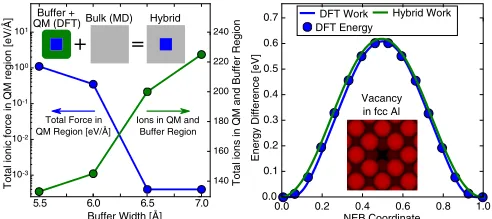
A prototypical hybrid simulation scheme is shown in Fig.1. To provide correct forces on atoms in the QM region, at each force call a DFT calculation is performed which contains the QM region, a surrounding “buffer” region, and a vacuum layer to remove periodic image effects. The presence of free surfaces in the DFT supercell induces electronic (though not elastic) surface states, whose effects must be contained within the buffer region, which in practice determines the required buffer width. For insulators dangling bonds are created whose effects can be suppressed through hydrogen bond termination, while in metals a charge dipole is induced with decaying Friedel oscillations [24]. As the buffer region is treated in DFT only to provide correct forces in the QM region, forces on atoms in the buffer (and bulk) region are given by the classical force field, following the “abrupt force mixing” coupling scheme, which gives accurate forces throughout the overall QM/MM system, in contrast to other handshaking methods that typically incur large force errors close to the QM/MM interface [11].
Here, DFT calculations are performed on clusters com-posed of QM and buffer atoms surrounded by vacuum. Alternative embedding approaches have been proposed for metals that use periodic QM calculations surrounded by bulklike regions instead of vacuum [16,25,26]. For example,
DFT Work Hybrid Work DFT Energy
Vacancy in fcc Al
1.0 0.2 0.4 0.6 0.8 0.0
NEB Coordinate 0.0
0.1 0.2 0.3 0.4 0.5 0.6 0.7
Energy Difference [eV]
Total ionic force in QM region [eV/Å]
Buffer + QM (DFT)
Buffer Width [Å] 5.5 6.0 6.5 7.0
10 10 10 10 10
140 160 180 200 220 240
Total Force in QM Region [eV/Å]
Ions in QM and Buffer Region
Total ions in QM and Buffer Region
+ =
Bulk (MD) Hybrid
FIG. 1. (Left) Convergence of DFT forces in a QM region of 12 perfect aluminium lattice ions with increasing buffer width. (Inset) Cartoon of the hybrid system. (Right) Comparison of NEB methods to calculate the migration barrier of a vacancy in fcc aluminum.
Woodward [16] modeled dislocation cores in periodic DFT cells by incorporating a domain boundary at the edge of the cell. This is appropriate where the embedding region is bulklike; however, the topology of dislocations and cracks of interest here restricts the general applicability of such an approach. We therefore used mixed boundary conditions, with periodicity retained in the direction along dislocation lines and crack fronts, and vacuum added in the other two directions.
For hybrid simulation schemes to produce accurate results, the quantum/classical transition region should typically be only weakly deformed by the presence of the defect, such that an interatomic potential with identical elastic properties and lattice constants (Bcl,acl) to the DFT system (Bqm,aqm)
would give an identical mechanical response. However, while modern interatomic potentials typically reproduce DFT elastic properties well, the agreement is not perfect; as a result, the atomic positions used for the classical calculation must be scaled by a factorα=aqm/aclsuch that atoms in a perfect bulk lattice are fully relaxed in both systems. In addition, using the classical and quantum bulk moduliBclandBqmto represent the
elastic properties of each medium, the classical atomic forces are scaled by a factorαβ, whereβ =Bqm/α3Bcl. A derivation
of this scaling is given in the Appendix. Beyond elastic matching, there are no further QM/MM interaction terms to be calibrated, unlike for energy-based QM/MM schemes where an interaction potential describing the energetic coupling between QM and MM regions must be specified [14].
Our hybrid force mixing implementation was performed in the Atomic Simulation Environment [27], usingLAMMPS [28] to generate classical interatomic forces and VASP [29] to perform DFT simulations using projected augmented wave pseudopotentials [30]. To test the force mixing scheme and buffer size we first considered a perfect fcc lattice of aluminum using an embedded atom method (EAM) interatomic potential by Liuet al.[31]. The QM region was a cube of 13 atoms, with a buffer region of widthwcontaining all atoms within a distancewfrom an atom in the QM region. In this instance the DFT system is a free cluster, meaning only a -point calculation is required, with a plane-wave cutoff of 320 eV. As there should be no residual forces on atoms in a perfect lattice configuration, we measured the total magnitude of atomic forces on all atoms in the QM region with buffer size. As shown in Fig.1, convergence was achieved for a buffer width of 6.5 ˚A, or around three atomic layers, with the total residual atomic force in the QM region being around 10−3eV/A, well˚
below the tolerance of at most 10−2eV/A per atom used during˚ structural minimization.
III. VIRTUAL WORK PRINCIPLE
The virtual work principle states that the energy E(r) required to traverse a pathway U(r)∈R3N, r∈[0,1] in
configuration space is given by
E(r)= −
U(r)
U(0)
dX·F(X)= −
r
0
dr∂U
∂r ·F(r
), (1)
whereF(r)≡F(U(r))∈R3N is the force vector for a given configurationU(r). When the force is a gradient field of some energy function V(X) (for which only the spatial gradient,
[image:3.608.50.296.590.700.2]namely, the force, can be calculated in hybrid simulations), it is simple to show that E(r)=V(U(r))−V(U(0)). We have implemented the virtual work principle in a modified nudged elastic-band-constrained minimization routine [10], evaluatingU(r) from a splined set of (possibly unconverged) NEB knots, using (1) to extract energy differences along the pathway. In the NEB routine an energy functional is only required to define the climbing image and, in some variations of the method, to determine the finite difference scheme used to construct pathway tangents. As a result, we first run iterations with no climbing image defined, until a certain tolerance in the maximum force component perpendicular to the pathway is reached, then use (1) to define energy differences along the pathway to identify a climbing image. Typically, a larger number of knots are required as compared to standard NEB calculations to ensure the splined configuration is as smooth as possible; we have found 10–15 knots to be adequate for all the systems considered here. In Fig.1we demonstrate an implementation of this method for the migration of a vacancy in fcc aluminum, treated in the hybrid scheme using only a single-point calculation, as the DFT region is again a free cluster. We also performed the same simulations in pure DFT using a 3×3×3 supercell of 107 atoms and a 7×7×7
k-point grid. In the latter case we are able to extract the total energy and therefore compare the accuracy of our method. As can be seen in Fig. 1, it is clear that the virtual work energy landscape as calculated in hybrid and DFT and the energy landscape as extracted from the total DFT energy are in extremely good agreement, demonstrating the convergence of the hybrid scheme and the validity of the virtual work principle. In contrast to the LOTF scheme, in which the QM region can be moved during a dynamical simulation, here we use the same set of QM atoms for all knots along the NEB path.
IV. MIGRATION OF AN100(010) EDGE
DISLOCATION IN MO
100(010) edge dislocations in bcc metals are known to migrate through a double-kink mechanism [32] and play an important role in irradiation damage of bcc metals, forming the core of 100 prismatic dislocation loops [33]. Edge dislocations possess a strong, long-ranged deformation field which, unlike 1/2111 screw dislocation dipoles [7,34], cannot be contained in periodic DFT supercells. As a result, flexible boundary DFT calculations [3] or the hybrid methods presented here must be used to capture the long-range elastic field. NEB calculations have been successfully applied to calculate the Peierls barrier to rigid dislocation motion in a wide variety of materials [7,20,34,35]. However, in order to correctly calculate a Peierls stress [7,35,36], care must be taken to accurately determine the dislocation core position as a function of the NEB coordinate r, captured through some remapping function xdislo(r). In the present setting
the complication of finding a suitable xdislo(r) does not
arise, as we focus on the zero stress double-kink formation energy, which controls the thermally activated diffusion of 100 prismatic dislocation loops [37]. By the chain rule one can demonstrate that the maximum energy difference
E=maxr[−
r
0 dr∂rU·F(r)] obtained in the virtual work
expression (1) is invariant under the substitution xdislo(r) and
70 80
Normalised Work
Hybrid MEAM
d
Distance d from core [Å]
(a) (b)
MEAM Cylinder MEAM Dipole
Energy Barrier [eV]
70 80 0.5
0.7 0.6
Dipole sep. / Cylinder radius [Å]
0.8 0.9
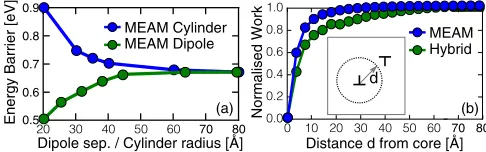
FIG. 2. (a) Comparison of dipole and cylinder geometries to calculate the Peierls barrier of an100(010) edge dislocation in MEAM molybdenum. (b) Localized work for the MEAM and hybrid systems as described in the main text, using Eq. (2).
thus does not affect our results. We note that existing methods [7,20] to calculate the Peierls stress through the determination of a suitable function xdislo(r) can be applied in postprocessing,
without modification, to the NEB pathways produced using our approach.
An 100(010) edge dislocation dipole of length b=
|a[100]| was formed in a square supercell such that the dislocation dipoles are separated by half the supercell height, with one dislocation migrating by a[001]. The system was relaxed using a recently developed modified embedded atom method (MEAM) potential by Parket al.[38], which includes an angular dependence to capture the highly directional bonding of bcc metals. We find the MEAM migration barrier converges with increasing system size and dipole separation, as shown in Fig.2; this size convergence was confirmed in calculations with a single dislocation in a cylindrical supercell, the outermost atoms fixed to the displacements predicted by anisotropic elasticity theory [39]. The size convergence of the migration barrier can also be investigated by considering the
localwork done by an atomj along the migration pathway
Wj(r)= −
r
0
dr∂uj ∂r ·fj(r
), (2)
where uj,fj ∈R3 are the per-atom values of U,F. With a saddle pointr=rs, the locality of the total work can be probed by summing all values ofWj(rs) less than a distanced from the dislocation core, shown in Fig.4(b). While it is clear that the immediate core region gives the dominant contribution to the migration barrier, the far field is essential to give a convergence result, which is only accessible to the hybrid simulation technique presented here. The final system used for our hybrid simulations consisted of around 10 000 atoms, far too large for a purelyab initiotreatment.
[image:4.608.313.556.71.147.2]THOMAS D. SWINBURNE AND JAMES R. KERMODE PHYSICAL REVIEW B96, 144102 (2017)
0 10 20 30 40 50
0 10 20 30 40 50
[100] [Å]
[010] [Å]
initial buffer final buffer initial core final core bulk atoms
[image:5.608.312.556.70.335.2][100](010) Edge Dislocation in Mo (12Å buffer)
FIG. 3. Illustration of the buffer and QM regions used to treat
100(010) edge dislocations in this work. The supercell has periodic boundary conditions in the dislocation line direction, [001].
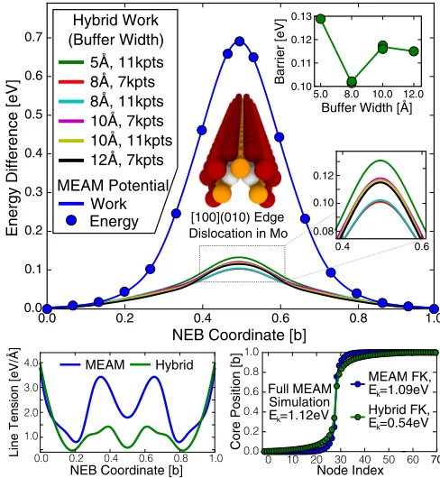
greater degree of deformation caused by the dislocation and the lower atomic density of the bcc structure. Nevertheless, across the range of buffer sizes andkpoints we find a variation from the final converged value of around 10%. Significantly, the value from our hybrid simulations is around 5 times smaller than that found using the MEAM potential, demonstrating the importance of usingab initioforces to treat highly deformed defect cores.
A. Kink formation energy
As the dislocations under study migrate through a kink mechanism, we have estimated the kink formation energy through careful parametrization of the well-known Frenkel-Kontorova (FK) model [32,40]. In the FK model, a regular array of N nodes of spacing a along the dislocation line direction are free to move in the perpendicular glide direction with positions (ia,xi),i∈[0,N−1]. The nodes are coupled by a line tension of strengthand a Peierls potentialVP(x)=
VP(x+b) of periodb, which is given in the current setting
by the Peierls potentialV(r) shown in Fig.4using the linear relation xi =xdislo(ri)=bri, givingVP(x)=V(x/b)=V(r).
The FK model has been successfully applied to calculate the kink formation energy on screw dislocations in bcc metals [32,40], though in the current setting we have found it necessary to allow an additional position dependence in(r), giving a total FK system energy
EFK[{r}]=
N
i=1
b2
a
(ri)+(ri−1)
4 (ri−ri−1)
2+V(r
i), (3)
where V(ri) is the migration potential shown in Fig. 4. To determine(r) and thus the kink formation energy, we will conjoin two copies of the dislocation core configurations with the same core positions r and calculate the restoring force between when the core positions differ by a small quantityδ. Explicitly, a line profileri =r+(i−N/2+1/2)δcan be formed in atomistic simulations (withN =2) by conjoining two NEB configurations U(r)∈R3N and U(r+δ)∈R3N
0.2 0.4 0.6 0.8 1.0 0.0
0.1 0.2 0.3 0.4 0.5 0.6 0.7
0.0
NEB Coordinate [b]
Energy Difference [eV] 0.08
0.10 0.12
0.4 0.6
MEAM Potential Work Energy 5Å, 11kpts 8Å, 7kpts 8Å, 11kpts 10Å, 7kpts 10Å, 11kpts 12Å, 7kpts Hybrid Work (Buffer Width)
5.0 10.0
0.10 0.13
0.11
8.0 12.0
0.12
Buffer Width [Å]
Barrier [eV]
[100](010) Edge Dislocation in Mo
Core Position [b]
70
Full MEAM Simulation
Ek=1.12eV Hybrid FK,E k=0.54eV
MEAM FK, Ek=1.09eV
Node Index NEB Coordinate [b]
MEAM Hybrid
Line Tension [eV/Å]
FIG. 4. (Top) Comparison of NEB methods to calculate the Peierls barrier of a 100(010) edge dislocation in molybdenum. (Bottom left) Line tension calculation using hybrid and MEAM force fields as described in the text. (Bottom right) Kinks formed in Frenkel-Kontorova models using the hybrid and MEAM values.
along the dislocation line direction to give an expanded system Uext(r,δ)∈R6N, being a dislocation line twice the original
length. In this extended system we can calculate the force to perturb the relative core positions byδ by projecting the force from atomistic simulationsF[Uext(r,δ)]∈R6N against
the tangent (∂/∂δ)Uext(r,δ)∈R6N, yielding a restoring force
f(r,δ)= ∂Uext(r,δ)
∂δ ·F[Uext(r,δ)]. (4)
The same line profile ri =r+(i−N/2+1/2)δ (where againN =2) can also be constructed in the FK model, which yields a restoring force to orderδof
fFK(r,δ)= −
2b2
a (r)δ−
∂rV(r)+δ∂r2V
+O(δ2). (5)
As we have already calculatedV(r) through a spline interpola-tion we can readily calculate the derivatives∂rV(r) and∂r2V(r) and thus can determine (r) by setting fFK(r,δ)=f(r,δ), which yields
(r)= −a
2b2δ[f(r,δ)+∂rV(r)]−
a
2b2∂ 2
rV +O(δ). (6)
We emphasize that while to extract accurate Peierls stresses a function xdislo(r) which correctly extracts the “true” dislocation
position is required, the formation energies calculated using the virtual work technique detailed here are independent of the choice of xdislo(r).
We have performed these calculations using both MEAM and hybrid forces to evaluatef(r,δ), yielding a calculation of
which we show in lower portion of Fig.4. The FK model (3)
[image:5.608.53.296.70.259.2]can then be used to simulate a much longer dislocation line to obtain a kink formation energy, which in the pure MEAM case can be directly compared to the kink formation energy in molecular statics [32]. This technique yields a kink formation energy of 1.12 eV, which is closely approximated by the MEAM FK kink formation energy of 1.09 eV. Due to the lower line tension and Peierls barrier found in our hybrid simulations, we find a much lower kink formation energy of 0.54 eV, just less than half the MEAM value. It is interesting to note that similar calculations [40] on111 screw dislocations in bcc Mo, using periodic DFT supercells, find a kink formation energy of 0.52 eV, meaning that both slip systems have similar activation energies for plastic flow [41].
V. BRITTLE CRACK GROWTH IN SILICON
As a final example, we carry out a direct ab initio
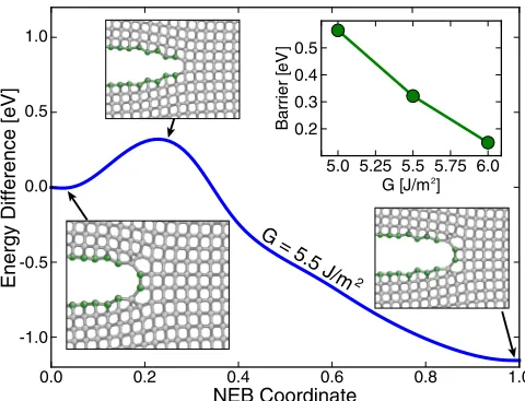
calculation of the discrete lattice trapping barriers [42,43] to brittle crack growth in silicon in the (110)[1¯10] cleavage system (Fig. 5). We modeled an 8112 atom system with dimensions 297×97.9×5.43 ˚A3, periodic along the crack front direction and with clamped top and bottom edges and applied strains corresponding to strain energy release rates of 5.0, 5.5, and 6.0 J/m2 (above the Griffith load of 3.44 J/m2
computed from the relaxed DFT surface energy [44]). An initial configuration withN =70 broken bonds along the crack line was relaxed using the force-based hybrid scheme using the Stillinger-Weber potential [45] for the MM region and DFT with the Perdew-Burke-Ernzerhof exchange-correlation functional for a QM region containing 32 atoms centered on the crack tip plus a buffer radius of 6 ˚A. The corrugated reconstruction of the (110) surface leads to a slightly blunted crack tip, with an alternating up-down structure that means the next stable minimum occurs with N+2 broken bonds. Applying the virtual work NEB approach with (N,N+2) end
NEB Coordinate
0.0 0.2 0.4 0.6 0.8 1.0
0.0 0.5 1.0
Energy Difference [eV]
G [J/m2]
Barrier [
e
V
] 0.5
0.4 0.3
0.2
5.0 5.25 5.5 5.75 6.0
G = 5.5 J/m
2
-0.5
[image:6.608.52.292.483.667.2]-1.0
FIG. 5. Minimum energy path for cleavage in the Si(110)[1¯10] fracture system, involving a blunt-sharp-blunt tip reconstruction with two bonds opening simultaneously. Inset images show near-tip region for the initial, transition, and final states following hybrid relaxation of the path, with undercoordinated atoms shown in green. Upper-right inset gives dependence of energy barrier on strain energy release rate, with fracture becoming easier as load increases.
points identifies a minimum energy path where two diagonally oriented bonds cleave simultaneously, passing through a sharp-tip transition state. The lattice trapping barrier decreases as the strain energy release rate is increased, predicting thermally activated crack growth rates similar to earlier work where DFT barriers could only be estimated from cluster calculations [44], but with the tip-blunting reconstruction indicating slow crack growth remains important for larger strain energy release rates than previously thought.
VI. CONCLUSION
In summary, we have proposed a method to compute energy barriers for activated processes that combines DFT and classical interatomic potentials in materials systems where strong bonds cross the interface between QM and MM regions. The method has been used to perform anab initiocalculation of the Peierls barrier for100(010) edge dislocations in Mo and to identify a novel crack advance mechanism in Si. The method is expected to be generally applicable to any system where localized chemical processes are driven by long-range elastic fields. For example, the technique could be applied to provide ab initio mechanistic insight into the dynamics of three-dimensional crack fronts, where fracture proceeds through kink formation and advance [44], or to provide a QM-based analog of the Rice-Thomson criterion for the transition from brittle cleavage to dislocation emission [46,47].
ACKNOWLEDGMENTS
This work has been carried out within the framework of the EUROfusion Consortium and has received funding from the Euratom Research and Training Programme 2014-2018 under Grant Agreement No. 633053, from the RCUK Energy Programme under Grant No. EP/P012450/1, from the Engineering and Physical Sciences Research Council under Grants No. EP/L027682/1 and No. EP/P002188/1 and from the Royal Society under grant RG160691. Computing facilities were provided by the Scientific Computing Research Technology Platform of the University of Warwick and the EUROfusion Marconi supercomputer facility. The views and opinions expressed herein do not necessarily reflect those of the European Commission.
All data created during this research are openly available from the University of Warwick Research Archive Portal (WRAP) athttp://wrap.warwick.ac.uk/91747.
APPENDIX: DERIVATION OF SCALING LAWS
We wish to define a position scalingαand energy scaling
βon the classical system to match the bulk moduli and lattice constant of the quantum system. We define a potential energy functionE(X), and then a scaled function
E(X)=βE(αX).
The corresponding force in the original coordinate system is
F(X)= −∂E
∂X = −βα
∂E
∂X =βαF(αX).
The equilibrium lattice constant changes from a0 to a0,
THOMAS D. SWINBURNE AND JAMES R. KERMODE PHYSICAL REVIEW B96, 144102 (2017)
according to
a0 = a0
α, V
0 =
V0
α3.
The scaled bulk modulus is
B=V∂
2E
∂V2 =βα
3V∂2E
∂V2 =βα
3B.
Thus if we want to match a target volumeV0and bulk modulus
Bwe should use
α=
V0
V0
1
3 =a0
a0, β =
B
Bα3,
where a0 and a0 are the lattice constants before and after
rescaling. For quantum/classical force mixing, where we label the quantum region as 1 and the classical region as 2, the aim is to rescale the classical region to match the quantum lattice constanta1and bulk modulusB1, so we have
α= a1
a2
, β= B1
B2α3
,
wherea2andB2are the unmodified classical lattice constant
and bulk modulus, respectively. The force scaling is thusαβ= B1/α2B2, as given in the main text.
[1] K. Burke,J. Chem. Phys.136,150901(2012).
[2] R. M. Martin,Electronic Structure: Basic Theory and Practical Methods(Cambridge University Press, Cambridge, UK, 2004). [3] C. Woodward and S. I. Rao,Phys. Rev. Lett.88,216402(2002). [4] A. F. Wright and S. R. Atlas,Phys. Rev. B50,15248(1994). [5] J. R. Kermode, T. Albaret, D. Sherman, N. Bernstein, P.
Gumbsch, M. C. Payne, G. Csányi, and A. De Vita,Nature (London)455,1224(2008).
[6] C. Varvenne, F. Bruneval, M. C. Marinica, and E. Clouet,Phys. Rev. B88,134102(2013).
[7] L. Dezerald, L. Ventelon, E. Clouet, C. Denoual, D. Rodney, and F. Willaime,Phys. Rev. B89,024104(2014).
[8] N. D. Hine, P. D. Haynes, A. A. Mostofi, C.-K. Skylaris, and M. C. Payne,Comput. Phys. Commun.180,1041(2009). [9] P. Hänggi, P. Talkner, and M. Borkovec,Rev. Mod. Phys.62,
251(1990).
[10] G. Henkelman, B. P. Uberuaga, and H. Jonsson,J. Chem. Phys.
113,9901(2000).
[11] N. Bernstein, J. R. Kermode, and G. Csanyi,Rep. Prog. Phys.
72,026501(2009).
[12] G. Lu, E. B. Tadmor, and E. Kaxiras,Phys. Rev. B73,024108 (2006).
[13] G. Csányi, T. Albaret, M. C. Payne, and A. De Vita,Phys. Rev. Lett.93,175503(2004).
[14] X. Zhang and G. Lu,Phys. Rev. B82,012101(2010). [15] X. Zhang, Q. Peng, and G. Lu,Phys. Rev. B82,134120(2010). [16] C. Woodward,Mater. Sci. Eng., A400-401,59(2005). [17] C. Woodward, D. R. Trinkle, L. G. Hector, Jr., and D. L. Olmsted,
Phys. Rev. Lett.100,045507(2008).
[18] D. R. Trinkle,Phys. Rev. B78,014110(2008).
[19] A. M. Z. Tan and D. R. Trinkle,Phys. Rev. E94,023308(2016). [20] D. Rodney, L. Ventelon, E. Clouet, L. Pizzagalli, and F.
Willaime,Acta Mater.124,633(2017).
[21] A. Nair, D. Warner, R. Hennig, and W. Curtin,Scr. Mater.63, 1212(2010).
[22] H. Hu and W. Yang,Annu. Rev. Phys. Chem.59,573(2008). [23] C. Várnai, N. Bernstein, L. Mones, and G. Csányi, J. Phys.
Chem. B117,12202(2013).
[24] N. W. Ashcroft and N. D. Mermin,Solid State Physics(Holt, Rinehart, and Winston, New York, 1976).
[25] J. Meyer and K. Reuter,Angew. Chem., Int. Ed.53,4721(2014). [26] L. Huber, B. Grabowski, M. Militzer, J. Neugebauer, and J.
Rottler,Comput. Mater. Sci.118,259(2016).
[27] A. H. Larsen, J. J. Mortensen, J. Blomqvist, I. E. Castelli, R. Christensen, M. Dułak, J. Friis, M. N. Groves, B. Hammer, C. Hargus, E. D. Hermes, P. C. Jennings, P. B. Jensen, J. Kermode, J. R. Kitchin, E. L. Kolsbjerg, J. Kubal, K. Kaasbjerg, S. Lysgaard, J. B. Maronsson, T. Maxson, T. Olsen, L. Pastewka, A. Peterson, C. Rostgaard, J. Schiøtz, O. Schütt, M. Strange, K. S. Thygesen, T. Vegge, L. Vilhelmsen, M. Walter, Z. Zeng, and K. W. Jacobsen,J. Phys. Condens. Matter29,273002(2017). [28] S. Plimpton,J. Comput. Phys.117,1(1995).
[29] G. Kresse and J. Furthmüller,Phys. Rev. B54,11169(1996). [30] G. Kresse and D. Joubert,Phys. Rev. B59,1758(1999). [31] X.-Y. Liu, F. Ercolessi, and J. B. Adams,Modell. Simul. Mater.
Sci. Eng.12,665(2004).
[32] T. D. Swinburne, S. L. Dudarev, S. P. Fitzgerald, M. R. Gilbert, and A. P. Sutton,Phys. Rev. B87,064108(2013).
[33] S. L. Dudarev, R. Bullough, and P. M. Derlet,Phys. Rev. Lett.
100,135503(2008).
[34] D. Rodney and L. Proville,Phys. Rev. B79,094108(2009). [35] R. Gröger and V. Vitek,Modell. Simul. Mater. Sci. Eng.20,
035019(2012).
[36] L. Dezerald, D. Rodney, E. Clouet, L. Ventelon, and F. Willaime, Nat. Commun.711695(2016).
[37] S. L. Dudarev, K. Arakawa, X. Yi, Z. Yao, M. Jenkins, M. R. Gilbert, and P. M. Derlet,J. Nucl. Mater.455,16(2014). [38] H. Park, M. R. Fellinger, T. J. Lenosky, W. W. Tipton, D. R.
Trinkle, S. P. Rudin, C. Woodward, J. W. Wilkins, and R. G. Hennig,Phys. Rev. B85,214121(2012).
[39] E. Clouet,Philos. Mag.89,1565(2009).
[40] L. Dezerald, L. Proville, L. Ventelon, F. Willaime, and D. Rodney,Phys. Rev. B91,094105(2015).
[41] J. P. Hirth and J. Lothe, Theory of Dislocations (Krieger Publishing, Malabar, FL, 1991).
[42] R. Thomson, C. Hsieh, and V. Rana,J. Appl. Phys.42,3154 (1971).
[43] N. Bernstein and D. W. Hess, Phys. Rev. Lett. 91, 025501 (2003).
[44] J. R. Kermode, A. Gleizer, G. Kovel, L. Pastewka, G. Csányi, D. Sherman, and A. De Vita,Phys. Rev. Lett.115,135501(2015). [45] F. H. Stillinger and T. A. Weber, Phys. Rev. B 31, 5262
(1985).
[46] J. R. Rice and R. Thomson,Philos. Mag.29,73(1974). [47] P. Andric and W. A. Curtin,J. Mech. Phys. Solids106, 315
(2017).