ISSN: 1816-949X
© Medwell Journals, 2020
Smart Highway Lighting Solution Based on Internet of Things
Parth Shah and P. Beaulah Soundarabai
Department of Computer Science, CHRIST (Deemed to be University), Bengaluru, India
Abstract: The main aim of this study is to reduce electricity wastage and manpower that is required to switch highway lights ON and OFF. Highway lights are one of the most important part of the modern society as they facilitate better vision at nights while driving and provide safety on roads. Highway lights, however, consume a lot of electricity. This study proposes a system that would reduce electricity wastage with the help of embedded technology that would control the highway lights based on the sunlight and motion on the road. With the help of Light Dependent Register (LDR) sensor, day or night can be detected. When night is detected by the LDR the lights on the highway would autonomously turn ON and when day is detected it would turn OFF automatically. The lights would be at 30% intensity when it is turned ON and as soon as it detects motion on road with the help of ultrasonic sensor it would increase the intensity to 100% and when the ultrasonic sensor doesn’t detect anyone on the highway the light intensity would go back to 30%. In addition, to this current sensor data is collected and stored in the database as it can be used to detect if the highway light is working or not. The system is reliable and cost-efficient as all the equipment used are less costly and available easily. Key words:Internet of Things (IoT), wireless sensor network, ultrasonic sensor, LDR sensor, Arduino, serial
connection
INTRODUCTION
A computer network is a digital telecommunication network between different nodes allowing them to exchange and share data and other resources. This connection between nodes or data links is done through cables wires such as optical fiber, coaxial cable or by wireless media like Wi-Fi, Bluetooth or cellular connection. The device that sends, receives or route data packets are known as nodes. In networking, packets are sent from one node to another.
A network connection is said to be wireless when it uses the wireless medium to transfer and share data among the nodes. In networks, packets are sent from one node to another. A network packet is a data which is formatted. The wireless network consists of Bluetooth, satellite communication network, wireless local area network, wireless sensor network.
Wireless Sensor Network (WSN) refers to spatially dispersed wireless sensors used for recording and monitoring the environment and the physical conditions. The data is then organized in a central location. WSN can measure conditions like sound, air pollution level, wind, temperature, humidity, etc.
A sensor is a device, subsystem or a module whose purpose is to sense or detect the changes or events and send these data to the server or another device. A sensor is basically used with other devices like microcontroller or computer. Things required for a good sensor are:
C It should be sensitive to the property that is being measured
C It should be insensitive to other properties C It should not influence the measured property Classification of the sensors:
C Analog sensor: an analog sensor produces an analog output based on the quantity being measured C Digital sensor: it is a sensor that works with discrete
or digital data
IoT or Internet of Things is a latest trend in the field of computer science. It is a network of devices in physical in nature which includes vehicles, consumer applications, etc. and other embedded devices with sensors, electronics, software, actuator and connectivity which enable the object to connect and exchange data. These online-capable devices are increasing at a rapid rate it has increased by 31% from 2016-2017 and it is estimated to reach 30 billion IoT products by 2020.
IoT allows objects to be sensed and controlled remotely within a network infrastructure. Due to this remote connectivity, many new opportunities are created for integration of the embedded system with physical devices that are computer-based systems. Switching from physical devices to computer-based systems would result in increased accuracy and efficiency with less reduced human intervention.
The word “Things” in the abbreviation of IoT refers to devices like biochips, health monitoring implants, camera streaming, automobiles with sensors and roads with sensors, etc. These devices have the capability to collect data with the help of sensors
and autonomously flow the data between devices. These devices can also be termed as smart devices.
A smart device can be stated as an electronic device connected to another device via. a network or other wireless protocols and can operate autonomously. With the help of IoT, smart devices can be created which can be used in different sectors. Some of the fields in which smart devices are currently being used are the consumer application, manufacturing, agriculture, energy management, environmental monitoring, medical and healthcare and transportation.
Energy consumption is a very big problem in research. This is because of the scarcity of resources such as fossil fuels. Research is being done to find alternative solutions and solutions for optimal utilization of these resources in the most efficient way possible without affecting the way things should work. With the help of IoT, we can try to solve this problem. In the present scenario, highway light is one of the most essential infrastructures of a city. But this infrastructure has a high economic and ecological cost. The highway light can account to nearly 10-38% of the total energy in the current world (Devi and Kumar, 2012). The current system or the present scenario uses a manual switch to control the highway light which wastes lots of energy if done at the wrong time. This problem of wastage of extra electrical energy can be solved by making highway lights more dynamic and with the use of new technologies like the internet of things and sensors to control the system.
In this study, the system that is being proposed might help in solving the problem of intensive wastage of electrical energy with low cost. The proposed model is capable of adjusting the level of the intensity of light of the Light Emitting Diode (LED) luminaires according to the environmental conditions. This is done through the data collected by different sensors monitoring the environment continuously. The sensors are mounted on the microcontroller. In our case, it is Arduino Nano in which the rules for controlling the system are defined. The LDR sensor is used to detect light in the environment, so that, it can switch ON the highway lights when the luminosity drops to a certain extent and when the sensor detects enough light, it will automatically switch OFF the highway lights. The proximity sensor is used to detect motion on the road, so that, if there is no motion then the luminosity of the lights is decreased to an extent that there is enough light for the pedestrians to walk on the road. When a vehicle is detected then the luminosity of lights would increase, so that, the vehicle can pass through properly without facing difficulties of poor visibility. This system can be implemented in a situation in which the vehicle passing rate is very low but the energy consumed is very high because of highway lights. In this kind of situation smart highway lights can reduce the intensity of
the lights and when it detects a vehicle the intensity would gradually increase, so that, energy is saved. The traditional method that is currently being used has the following problems:
C Use of sodium vapor lamps consume higher energy C Manual switching ON and OFF lights
C High consumption of energy when there is no one in the road
Literature review: On reading and coming across different papers of different authors several different factors were introduced. Some researchers mentioned the use of LED lights as they have a longer lifespan and are highly affective. They suggested just changing the lights to LED lights will save 50% energy. Different authors used different frameworks to manage the road lighting like the use of GSM technology, LDR sensor and different ways of detecting motion.
The paper proposed by Abinaya et al. (2017) suggested a system which would act as an energy saving system as well as a security surveillance system. The system that is being proposed is autonomous and uses LDR sensor for turning lights ON or OFF with the help of microcontroller. By this way the paper implemented energy saving system. The paper also proposed on installing cameras on the street light to track people and other actions on the road and also proposed of installing panic buttons on the poles of street light which would alert the police. The whole system is connected with cloud Saifuzzaman et al. (2017) proposed a smart system which has the ability to autonomously control street lighfts and to switch on or off the lights according to day or night and the default luminosity of the light is kept to low and as the movement is detected on the road the luminosity is increased to high. The framework also included a way to manage law and order in roads with the use of barriers on the roads and cameras placed at regular interval to help the traffic police. The framework uses IR sensor for detecting motion and is able to save 30-35% electricity.
The paper proposed by Bhairi et al. (2017) uses a framework which uses PIR sensor to detect motion. The prototype uses solar energy for powering the street light and LDR sensor to detect day or night. In the proposed system, the intensity of the light is decreased to 30% when there is no motion detected on the road and as soon as the motion is detected the street light would glow to 100%. As the system uses solar power to run it stores energy in battery and that energy is used at night to power up the street lights.
NODEMCU ESP-32
Current sensor
Current sensor
Current sensor
Current sensor
LDR sensor
Arduino Arduino Arduino Arduino
Ultrasonic sensor
Ultrasonic sensor
Ultrasonic sensor
Ultrasonic sensor
or night. The paper shows the different stages of changes in luminosity of LED light and its effect on the energy consumption.
The smart street light management system proposed Dheena et al. (2017) uses LDR sensor for turning lights on or off based on the lighting and weather conditions. The prototype senses weather conditions near the street light using the DHT11 (Temperature and Humidity Module) and sends the weather data to the server using ESP-8266. The prototype uses arduino as the microcontroller.
The framework proposed by Maguluri et al. (2017) uses the LDR sensor to detect light if it is dark then it keeps the light’s luminosity to 60% and uses photovoltaic sensor to detect motion. As the motion is detected the light glows to 100%. The proposed model uses solar electricity for lighting the street lights.
MATERIALS AND METHODS
Smart highway lighting system: The prototype that is being proposed provides a solution for controlling and managing highway lights so that it consumes less electricity. The system consists of LDR sensor, ultrasonic sensor, current sensor, Arduino and NODEMCU ESP-32. Arduino microcontroller is used to control the lights as it fetches data from the sensors. NODEMCU ESP-32 has the ability of multithreading which is used to calculate current sensor data from multiple highway lights and send to the server. The entire system can be monitored through a web based interface. At a time, this prototype could connect 8 highway lights. In this proposed model the conventional lamp is replaced with the LED lamp and the smart lighting technology. The LED lamp consumes less
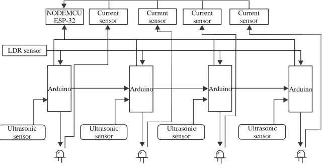
[image:3.612.140.460.534.698.2]power and gives high intensity light which can effectively illuminate the surroundings. The LDR sensor is the sensor having the ability to detect day or night. The sensor returns a value between 0-1023 based on the intensity of the light. It returns a high value (>700) when it is night as its resistance increases and low value (#700) when it is day as its resistance decreases. As the data is sent from LDR sensor to Arduino, it can detect low or less light. When it detects less environmental light, Arduino will send the command to start the highway light at an intensity of 30%. In the prototype all the highway lights would have an ultrasonic sensor. It is used to detect motion. The ultrasonic sensor works on the principal of SONAR, i.e., it will send ultrasonic sound waves from the emitter. If there is an object in front of ultrasonic sensor, then, the sound waves will be reflected or echoed back which will be picked up by the receiver which will record the time difference is the output of the sensor. After getting the time difference, distance can be calculated. If the distance is less than the threshold value that is the width of the road, then, the Arduino will increase the brightness of that highway light and the highway light next to that light. The highway lights will have a serial connection to make this task possible. The highway light will communicate with each other if an obstacle or movement is detected or not. The change in the intensity is handled through Pulse Width Modulation (PWM). All the highway lights are connected with current sensor (ACS712) which send the current data to NODEMCU ESP-32 which has the capability of multithreading using MicroPython, so, it can send data of multiple highway lights to the server. With the help of current data, we can get the power consumption and if the light is working or not. Figure 1 shows the architecture of the proposed model.
In this, we can see that all the highway lights have an Arduino and work as a single node and the Arduino are connected with a serial connection with the neighboring arduino. Each Arduino has an ultrasonic sensor and multiple Arduino are connected to same LDR sensor. All the highway lights are connected to current sensor which is connected to NODEMCU ESP-32 which is responsible for sending the data to the cloud.
Hardware specification: The proposed system uses following the following tools for the prototype.
Arduino nano: The Arduino Nano is a microcontroller with the operating voltage of 5V and its input voltage is from 7-12V. There are 14 digital pins which has the ability to work for both input and output. Out of these 14 pins there are 6 pins which havecapability of 8-bit pulse width modulation. Arduino Nano has 8 analog pins each of which can provide 10 bits of resolution.
NodeMCU: NodeMCU is a development board which has built in Wi-Fi and Bluetooth module. The operating voltage of this board is 3.3V and the input voltage is between 7-12V. The board has 24 digital I/O pins, 8 analog input pins and 2 analog output pins. The board has a flash memory of 4MB, SRAM of 520KB and clock speed of 240 MHz.
Sensors
HC-SR04: HC-SR04 is an ultrasonic sensor used to find distance between objects. It works on the principle of RADAR or SONAR. The ultrasonic sensor transmits ultrasonic sound and when it hits an object it’s echo is received by the receiver. The output received is the time taken by the echo to reach the sensor. Through this distance is calculated. The range of the HC-SR04 is 2-400 cm.
LDR sensor: The LDR sensor or Light dependent register is a register which has the ability to pass high voltage (low resistance) when there is low light and low voltage (high resistance) when there is enough light. The sensor sends analog value in a range of 0-1023. When there is enough light the value is above 700 till 1023 and when it is less than that it means there is less light. The sensor takes in 5V current.
ACS712: ACS712 is a current sensor used to detect and measure current using the principle of hall effect. It is available in different variants according to the current that is to be detected. It comes with 5, 20 and 30A variant. The input voltage of this sensor is 5V.
LED: LED or light emitting diode is a two lead semiconductor which emits light when a suitable current is applied to it. It has a property to glow or change the
intensity of the light that is emitted when there is a change in the input current that is higher the current higher is the intensity of the light. If the input current is reduced the light intensity will decrease. It is because of this property; LED is used in this research. LED is also energy efficient and uses less electrical energy than the incandescent, sodium vapour and other lamps. The proposed system uses 5V LED lights.
Modules in the system: The system consists of 3 main modules.
Control unit: The microcontroller, Arduino is the key component in this module as LDR sensor and ultrasonic sensor are connected with it. Arduino Nano collects the data from these sensors and with the help of this data it decides the action that is to be taken.
Detection unit: The detection unit consists of all the sensors. The main work of the detection unit is to send data to the microcontroller. The detection unit helps to detect whether it is day or night, there is motion on the road or there is no one on the road. In this module the current data of the highway light is also sent to the microcontroller.
Analysis unit: In this unit the current data is analyzed and power consumption is calculated. From the data it is easier to know when the light is at full intensity or at 30% intensity or it is switched OFF and we can make charts to show at what time how much power is consumed.
Proposed algorithm: The main function of this system is to reduce the electricity consumption without affecting the normal human life. The algorithm takes input from different sensors in order to determine the action to be taken. For this algorithm to work the following constraints should be fulfilled:
C The highway light should be installed with LED light C The module should be deployed in the highway light C Ultrasonic sensors should be placed on the road few
meters ahead of the highway light
Start
Receive data from LDR sensor
Day Check if Night day of night
Lights OFF from ultrasonicReceive data sensor
Detect motion
No Yes
Lights intensity 30%
Lights intensity 100%
Collect current sensor data and upload in cloud
End
light and the whole system runs in an infinite loop. The algorithm is for controlling street light is described as follows:
Step 1
SET trigPin to 4 SET echopin to 5 SET ledPin to 9 SET ultrasend to 6 SET sensorpin to A5 SET SensorValue to 0 SET ultrarec to 2 SET ultrasensor value to 0 Step 2
SET ledpin as OUTPUT PIN SET ultrasend as OUTPUT PIN SET ultrarec as INPUT PIN
[image:5.612.68.506.104.636.2]SET trigpin as OUTPIN PIN SET echopin asOUTPIN PIN SET Baudrate to 9600 bits per second REPEAT WHILE TRUE step 3-10
Fig. 2: System flowchart
Step 3
Set the trigpin to 0 for 2 microseconds Step 4
Read the value from sensorpin and store it in SensorValue
Read the value from ultrarec and store it in ultrasensor value
Step 5
Set the trigpin to 1 for 10 microseconds Step 6
Set the trigpin to 0 Step 7
Read the sound wave travel time from echo pin and store it in duration
Step 8
Convert duration into centimeter and store in cm Step 9
IF cm is <40 and SensorValue >700 Set brightness to 255 Set ultrasend to 1 Set ledpin to brightness Delay by 100 microseconds ELSE IF ultrarec is equal to 1 then
Set brightness to 255
Set ledpin to brightness Delay by 100 microseconds
ELSE IF sensorValue is >700 Set brightness to 100 Set ultrasend to 0
Set ledpin to brightness ELSE
Set ultrasend to 0 Set ledpin to 0 Step 10
Send current and voltage data to the server
RESULTS AND DISCUSSION
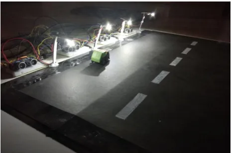
[image:5.612.190.423.559.713.2]The proposed system is simulated in small scale prototype showing the different scenarios and the data of current sensor is stored in the database to show the how much electricity is consumed in different scenarios. The arduino microcontroller is used as the main component in which code for the sensors is written and uploaded in its flash memory. Figure 3 shows the prototype that was implemented. Table 1 shows the different scenarios and the result generated.
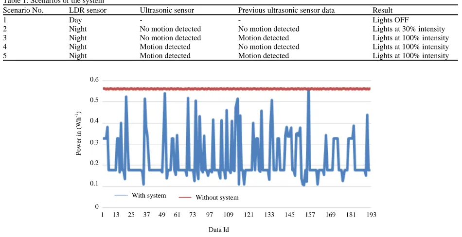
Table 1: Scenarios of the system
Scenario No. LDR sensor Ultrasonic sensor Previous ultrasonic sensor data Result
1 Day - - Lights OFF
2 Night No motion detected No motion detected Lights at 30% intensity
3 Night No motion detected Motion detected Lights at 100% intensity
4 Night Motion detected No motion detected Lights at 100% intensity
5 Night Motion detected Motion detected Lights at 100% intensity
Fig. 4: Current sensor data
Figure 4 shows the energy consumption data. The data that is being recorded is of 15 min in two scenarios, i.e., when the light is light is in full intensity and when the highway light uses the smart highway lighting system. The blue line represents the current sensor data when light is at full intensity and the orange line represents when the highway light uses the smart highway lighting system. The proposed system used 55% less energy compared to the existing scenario.
CONCLUSION
The main aim of this system is to reduce electricity wastage from highway lights. The proposed system solves this problem by replacing the Sodium vapour lamps with LED Lights which would cut down electricity wastage to nearly 60% and then implementing the solution proposed which would further decrease the energy consumption by 55%. This system is a feasible solution and if implemented properly this could save a lot of electricity wastage. The proposed model is fully extendable and modifiable. Many new components can be added in future like CCTV camera integration, air pollution monitoring.
REFERENCES
Abinaya, B., S. Gurupriya and M. Pooja, 2017. IoT based smart and adaptive lighting in street lights. Proceedings of the 2017 2nd International Conference on Computing and Communications Technologies (ICCCT’17), February 23-24, 2017, IEEE, Chennai, India, pp: 195-198.
Bhairi, M.N., S.S. Kangle, M.S. Edake, B.S. Madgundi and V.B. Bhosale, 2017. Design and implementation of smart solar LED street light. Proceedings of the 2017 International Conference on Trends in Electronics and Informatics (ICEI’17), May 11-12, 2017, IEEE, Tirunelveli, India, pp: 509-512.
Bhangdiya, V.K., 2016. Low power consumption of LED street light based on smart control system. Proceedings of the 2016 International Conference on Global Trends in Signal Processing, Information Computing and Communication (ICGTSPICC’16), December 22-24, 2016, IEEE, Jalgaon, India, pp: 619-622.
Devi, D.A. and A. Kumar, 2012. Design and implementation of CPLD based solar power saving system for street lights and automatic traffic controller. Int. J. Sci. Res. Publ., Vol. 2, No. 11. 10.13140/ RG.2.2.11523.60963.
Dheena, P.F., G.S. Raj, G. Dutt and S.V. Jinny, 2017. IOT based smart street light management system. Proceedings of the 2017 IEEE International Conference on Circuits and Systems (ICCS’17), December 20-21, 2017, IEEE, Thiruvananthapuram, India, pp: 368-371.
0.6
0.5
0.4
0.3
0.2
0.1
0
Power in (W
h
-1)
1 13 25 37 49 61 73 97 109 121 133 145 157 169 181 193
With system Without system
Maguluri, L.P., Y.S.V. Sorapalli, L.K. Nakkala and V. Tallari, 2017. Smart street lights using IoT. Proceedings of the 2017 3rd International Conference on Applied and Theoretical Computing and Communication Technology (iCATccT’17), December 21-23, 2017, IEEE, Tumkur, India, pp: 126-131.