brine causes a driving force for transport of Mg2# ions from the feed into the brine. Countercurrent operation allows the large driving force to be main-tained over the length of the membrane.
A hollow-Rbre device has been used as a suppressor for ion chromatography. Compared to an ion-ex-change column that is normally used to suppress conductance in the eluant, Donnan dialysis allowed more control over the conductivity and eliminated the need to regenerate the resins. Moreover, the resolution was improved by the use of Donnan dialysis.
The use of neutralization dialysis for desalination of cheese whey has been described.
Conclusion
Donnan dialysis can be used in many applications where ion-exchange beads are currently applied. The process mightRnd a niche in water softening in a ca-pacity range between that of home water softeners and the large-scale lime-soda softeners. Capital costs are higher for membranes than for resin beads, but the use of membranes offers the advantages of steady-state operation without the need for rinse-down, which produces large volumes of water that must be discarded. The capital cost of small-scale Donnan dialysis could be reduced by the availability of more ion-exchange membranes in hollow-Rbre form that could be assembled into compact modules.
Further Reading
Bleha M and Tishchenko GA (1992) Neutralization dialysis for desalination. Journal of Membrane Science 73: 305}311.
Davis TA, Wu JS and Baker BL (1971) Use of the Donnan equilibrium principle to concentrate uranyl ions by an ion-exchange membrane process.AIChE Journal17(4): 1006}1008.
Donnan FG (1924) The theory of membrane equilibria.
Chemical Reviews1(1): 73}90.
Grot WG (1986) Ion Exchange Process and Apparatus. U.S. Patent 4,591,439.
Ng PK and Snyder DD (1981) Mass transport character-istics of Donnan dialysis: the nickel sulfate system.
Journal of the Electrochemical Society 128(8):
1714}1719.
Ng PK and Snyder DD (1983) Uranyl nitrate and nitric acid. Combined electrodialysis and dialysis for regenera-tion of chromic acid etching soluregenera-tion.Journal of Mem-brane Science13: 327}336.
Nonaka T, Ogawa H, Morikawa M and Egawa H (1992) Uphill and selective transport of uranyl ions through 2,3-epithiopropyl methacrylate-2-acrylamide-2-methyl propanesulfonic acid copolymer membranes.Journal of Applied Polymer Science45: 285}292.
Nonaka T and Fujita K (1998) Transport of ferric ions through 2,3-epithiopropyl methacrylate}dodecyl meth-acrylate}methylacrylamide propyltrimethylammonium chloride terpolymer membranes.Journal of Membrane Science144: 187}195.
Roach ET (1985) Evaluation of Donnan Dialysis for Treatment of Nickel Plating Rinse Water. Final Report to U.S. Environmental Protection Agency, NTIS PB85-200046.
Stevens TS and Davis JC (1981) HollowRber ion-exchange suppressor for ion chromatography.Analytical Chem-istry53: 1488}1492.
Wallace RM (1967) Concentration and separation of ions by Donnan membrane equilibrium.Industrial and En-gineering Chemistry,Process Design and Development
6(4): 423}431.
Electrodialysis
H. Strathmann, University of Twente, The Netherlands
Copyright^ 2000 Academic Press
Electrodialysis is a process in which ion exchange membranes in combination with an electrical poten-tial difference are used to remove ionic species from an aqueous solution. The large scale industrial utilization of the process began about 30 years ago with the development of highly selective ion exchange membranes of low electric resistance arranged in a multicell stack.
Until the mid 1970s electrodialysis stacks were operated in a unidirectional mode, that is, the
polar-ity of the electrodes was Rxed. A signiRcant step towards the efRcient application of electrodialy-sis was the introduction of a new mode of operation referred to as electrodialysis reversal. In this operat-ing mode the Sow streams and the polarity in an electrodialysis stack are periodically reversed, which reduces membrane fouling and scaling. Costly and time-consuming membrane cleaning procedures are then unnecessary.
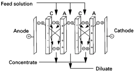
Figure 1 Schematic diagram illustrating the principle of elec-trodialysis.
Figure 2 Schematic drawing illustrating the structure of a cation exchange membrane.
utilization of electrodialysis in the food and chemical industry and to treat certain industrial efSuent streams has become important.
The Principle of Electrodialysis
The principle of electrodialysis is illustrated in Figure 1. A typical electrodialysis cell arrangement consists of a series of anion and cation exchange membranes arranged in an alternating pattern be-tween an anode and a cathode to form individual cells. If an electrolyte solution is passed through these cells and an electrical potential is established between the electrodes, the positively charged cations migrate towards the cathode and the negatively charged an-ions towards the anode. The positively charged cations can easily permeate the negatively charged cation exchange membrane but are retained by the positively charged anion exchange membrane. Like-wise, negatively charged anions permeate the anion exchange membrane but are retained by the cation exchange membrane. The overall result is an increase in the ion concentration in alternate compartments, while the other compartments simultaneously become depleted. The depleted solution is referred to as diluate and the concentrated solution as brine or concentrate. The driving force for the ion transport in the electrodialysis process is the applied electrical potential. The total space occupied by the diluate and the concentrated solutions and the contiguous anion and cation exchange membranes make up a cell pair. The cell pair is the repeating unit in an electrodialysis stack.
The Ion Exchange Membranes
Ion exchange membranes are the key components in electrodialysis. They consist of highly swollen gel-type polymer structures carrying Rxed positive or negative charges. Polymer structures carrying negatively charged groups are referred to as cation
exchange membranes, while those carrying positively charged groups are referred to as anion exchange membranes.
In a cation exchange membrane, theRxed negative charges are in electrical equilibrium with mobile ca-tions in the interstices of the polymer.Figure 2shows a cation exchange membrane with Rxed anions and mobile cations; the latter are referred to as counter ions. The mobile anions, called co-ions, are more or less completely excluded from the polymer matrix because their electrical charge is identical to that of theRxed ions. Because of the exclusion of the co-ions, cation exchange membranes are preferentially per-meable for cations. Anion exchange membranes which carry positive Rxed charges and exclude ca-tions are preferentially permeable to anions. The ex-tent to which co-ions are excluded from an ion exchange membrane depends on the membrane as well as on the solution properties.
The most desirable properties for ion exchange membranes are:
E High permselectivity } the membrane should be permeable to counter-ions only
E Low electrical resistance } the membrane should have high counter ion permeability
E Good mechanical and form stability } the membrane should be mechanically strong and should have a low degree of swelling in diluate solutions
E High chemical stability}the membrane should be stable over the entire pH range and in the presence of oxidizing agents and organic solvents.
[image:2.568.306.503.526.680.2]stability of the membrane. The type and concentra-tion of the Rxed ions determine the permselectivity and the electrical resistance. The moieties often used asRxed charges are}SO\3 and}COO\groups
in cation exchange membranes and }R3N# and
}R2NH#groups in anion exchange membranes. The
sulfonic acid group }SO\3 is completely dissociated
over the entire pH range, while the carboxylic acid group }COO\ is virtually undissociated in the pH range (3. The quaternary ammonium group }R3N#again is completely dissociated over the entire
pH range, while the tertiary ammonium group }R2NH# is only weakly dissociated. Accordingly,
ion exchange membranes are referred to as weakly or strongly acidic or basic in character depending on the charged groups they contain.
Mass Transfer in Electrodialysis
Mass transfer in electrolyte solutions is determined by the driving forces acting on the individual ions of the solution and by the friction of the ions with other components in the solution. The driving forces can be expressed by gradients in the electrochemical poten-tial of individual components. The friction that has to be overcome by the driving force can be expressed by the ion mobility or diffusivity.
To describe the mass transport in a system, thermo-dynamic and kinetic parameters must be mathemat-ically related. Several relations are described in the literature. The one most frequently used is the Nernst}Planck equation which describes transport of ions under isobaric and isothermal conditions in an ion exchange membrane as follows:
Ji"miCi
di
dz"miCi
ziFd dz#
di
dz
"miCi
ziFd dz#RT
d lnai
dz
[1]For the deRnition of symbols in this and all other equations, see Table 1. Ji is the Sux in the
direc-tion perpendicular to the membrane surface and z
refers to the number of charges carried by an ion and indicates whether these charges are positive or negative.
A boundary condition for describing the mass transport in electrolyte solutions is the electroneutral-ity requirement which postulates that on a macro-scopic scale there is no excess in positive or negative charges. Thus:
i
ziCi"0 (i"1, 2, 32n) [2]
The concentration of individual ions is related to that of the salt by the stoichiometric coefRcient which determines into how many ions a salt will dissociate in the solution. Thus:
Ci"iCs [3]
Another assumption in electrodialysis is that elec-trical charges are transported exclusively by ions. Thus:
I"
i
ziFJi [4]
HereJiis theSux of the individual ions andIis the
total electrical current.
Transport and Transference Numbers
The transport numberTiand the transference number
tiof an ioniare given by:
Ti" ziJi
i ziJi
and ti"Ti zi"
Ji
i ziJi
[5]
Here Ti indicates the fraction of the total current
carried by the ioni, andtidetermines the number of
moles of the ionitransported per mole of electrons, i.e. per Faraday.
The transference number is directly related to the ion concentration and their mobility and its sum is 1. Thus:
ti" Cimi
i ziCimi
and
i
ti"0 [6]
The transference numbers of different salt ions in solution are not very different. In an ion ex-change membrane, however, there are theRxed ions of the membrane in addition to the mobile ions of the electrolyte. The Rxed ions do not contribute to the transport of electrical charges. Their transference number is therefore 0. Furthermore, the concentra-tion of the counterions is much lower than that of the co-ions. Their concentration in the membrane deter-mines the permselectivity of a membrane.
Membrane Permselectivity
The permselectivity of cation and anion exchange membranes is deRned by:
mc"t mc c !tc
ta
and ma"t
ma a !ta
tc
Table 1 Definition of symbols used in mathematical equations
Symbol Definition
Electrochemical potential
Chemical potential
Electrical potential
Stoichiometric coefficient which determines into how many ions a salt will dissociate in the solution
Permselectivity of a membrane
Current utilization
Thickness of a cell
Resistance of ion exchange membranes
Potential difference between solutions separated by a membrane assuming electrochemical equilibrium
C Difference in salinity of feed and product water
Don Donnan potential
G Energy required for production of the dilute
m
! Average activity coefficients of salt in the mem-brane ns Amount of salt in moles transferred from a feed to
a concentrate solution
p Hydrodynamic pressure loss through the stack
s Equivalent conductivity
s
! Average activity coefficients of salt in the electrolytesolution z Thickness of the boundary layer
a Activity A Effective area
Amin Minimum membrane area required for a certain
plant capacity
C Concentration differences between feed and diluate Cm
co Co-ion concentration in the membrane
Cm
f Concentration fixed ions in the membrane
Cs
co Co-ion concentration in the electrolyte solution
D Diffusion coefficient
dz Directional coordinate perpendicular to the mem-brane surface
Edes Energy required for desalination
Ep Pumping energy
F Faraday constant I Total electrical current i Current density ilim Limiting current density
Ji Flux of componenti (individual ions)
k Constant referring to efficiency of pumps m Mobility of ions in the membrane n Number of cell pairs in a stack Q Volumetric flow of the product R Gas constant
R Electric resistance T Temperature t Transference number t Time
Ti Transport number of componenti (ions)
u Linear flow velocity of solution in electrodialysis cells
U Voltage drop across the electrodialysis stack V Volume
z Electrochemical valence
Superscripts
and Two phases separated by the membrane b Boundary layer
ba Concentrate bulk solution bc Concentrate bulk solution
Table 1 Continued
Symbol Definition
bd Diluate solution in the bulk diff Ion diffusion
l Current leakage through the manifold m Membrane
ma Anion membrane mc Cation membrane
md Diluate solution at the membrane surface mig Ion migration
ms Membrane selectivity o Feed
p Product solution s Solution
sc Concentrate solution sd Diluate concentration se Electrode rinse solution sf Feed solution
sp Product solution
w Water transport through the membranes
Subscripts
a Anion c Cation cou Counterion
i Ion
s Salt w Water
The permselectivity of an ion exchange membrane relates the transport of electric charges by counter-ions to the total transport of electric charges through the membrane. An ideal permselective cation ex-change membrane would transmit positively charged ions only, i.e. fortmc
c "1,mc"1. The
permselectiv-ity approaches zero when the transference number within the membrane is identical to that in the elec-trolyte solution. For the anion exchange membrane the corresponding relationship holds.
Diffusion Potential, Donnan Equilibrium and Ion Exclusion
The diffusion potential can be derived by integ-ration of eqn [1] and is given for a monovalent elec-trolyte when the ion activity is expressed by the salt concentration by:
"!"RFT
ma!mcma#mc
lnCs
Cs
[8]
which is generally the case with ion exchange mem-branes. This potential difference is referred to as the Donnan potential.
The Donnan potential cannot be measured directly. It can, however, be calculated from the electrochemi-cal equilibrium of ions between the membrane and the adjacent solution. By introducing the proper rela-tions for the electrochemical potential, the Donnan potential } the electrical potential difference be-tween an ion exchange membrane and a solution of a monovalent salt }can be calculated to aRrst ap-proximation by:
Don"m!s"RT
F ln
am i
as i
[9]
The numerical value of Don is negative for the
cation exchange membrane and positive for the anion exchange membrane in equilibrium with a dilute electrolyte solution.
The Donnan potential is also the basis for calculating the Donnan exclusion, which determines the co-ion concentration in a membrane. For a mono-valent electrolyte, i.e. zi"1, and assuming a high Rxed ion concentration in the membrane com-pared to the electrolyte concentration, the co-ion concentration in the membrane is given to a Rrst approximation by:
Cmco"C s
co
Cm
f
s
!
m
!2
[10]
Energy Requirements in
Electrodialysis
The energy required in an electrodialysis process is the sum of two terms: Rrstly, the electrical energy needed to transfer the ionic components from a feed solution through the membranes into the con-centrate solution, and secondly, the energy required to pump the solutions through the electrodialysis unit. Energy consumption due to electrode reactions can generally be neglected because of the large num-ber of cell pairs usually stacked between the two electrodes.
Minimum Energy Required for Transfer of Ions from a Feed to a Concentrate Solution
In electrodialysis the minimum energy required for the transport of salt from a feed to a concentrate solution can be expressed by the Gibbs free energy of mixing. Taking into account the electrolyte concen-trations in the feed, diluate and concentrate, the
min-imum desalting energy is given by:
G"zRTns
lnC
sf s
Csc s
Csf s
Csc s
!1
!
lnC
sf s
Csd s
Csf s
Csd s!1
[11]
Practical Energy Requirements in Electrodialysis
As discussed previously, the minimum energy re-quired for desalting a given feed solution refers to a reversible process. In electrodialysis there are also irreversible energy losses and the total electric energy required for the transfer of ions from a feed solution to a concentrate, i.e. the actual energy used for desali-nation is much larger than the theoretical minimum value. This is given by:
Edes"UIt"RI2t [12]
The electric current required for the desalination of a feed solution is directly proportional to the concentration difference between the feed and the diluate solution. It is given by:
I"V
pz
azcvsF(Csfs!Csps)
t [13]
The current utilization is the fraction of the total current passing through the electrodialysis stack that is used for the transfer of ions. It will be discussed in more detail later.
The electrical resistance of an electrodialysis stack is determined by the resistances of the membrane and diluate and concentrate solutions and is given to aRrst approximation by:
R"U
I" n A
2 s
1
Csd
s#
1
Csc
s
#ma#mc
[14] The electrical resistance of the solutions is inversely proportional to their salt concentrations, which are changing while passing through the stack from the feed to the product concentration. The concentration in the diluate cell is decreasing and that in the concen-trate cell increasing. An electrical resistance of a stack can thus be calculated as a function of the cell thick-ness, i.e. the distance between two membranes. Gen-erally, the resistances of the ion exchange membranes and the average resistance of the concentrate solution are much lower than the average resistance of the diluate and can therefore be neglected.average of the diluate concentration and is given by:
R"n A
lnC
sf s
Csp s
s(Csfs!Csps)
[15]
The superscripts sf and sp refer to the feed and the diluate at the cell outlet, which is the required prod-uct.
A combination of eqns [13] and [15] gives the energy required to remove a certain amount of salt from a feed solution. For the desalination of a mono-valent salt, i.e. where za, zcand vs are all unity, the
electrical energy is given by:
Edes"n A
Vp2
F2(Csf s!Csps)
lnC
sf s
Csp s
s
[16]
For a given plant capacity, salt solution and cell design, the equivalent conductivity and the number and area of cells are constant. Thus, the energy re-quired for the desalination of a monovalent salt solu-tion can be expressed to aRrst approximation by the constant factork, by the current utilization and by the feed and the product concentration.
Edes"k
(Csfs!Csps) log
Csf s
Csp s
[17]
Pumping Energy Requirements
The operation of an electrodialysis unit requires one or more pumps to circulate the diluate, the concen-trate and the electrode rinse solution through the stack. The energy required for pumping these solu-tions is determined by the volumes to be circulated and the pressure drop. It can be expressed by:
Ep"k(Vpsd#Vscpsc#Vsepse) [18]
Processes Affecting the
Ef
\
ciency of Electrodialysis
In practical application electrodialysis is effected by concentration polarization and by incomplete cur-rent utilization. Both phenomena inSuence the ef-Rciency of the process.
Current Utilization
Current utilization in an electrodialysis stack is im-paired by incomplete membrane selectivity, parallel
current through the stack manifold and water trans-fer across the membranes due to osmosis and electroosmosis.
The ratio of the actual current needed for salt transport from a feed to a concentrate stream to that calculated theoretically is referred to as the current efRciency, which for one cell pair is given by:
"mswl [19]
The efRciency term ms is a function of the
membrane permselectivities.wis caused by
convec-tive Sow due to the hydrostatic pressure differ-ence between the diluate and concentrate cells, by transfer of water in the hydration shell of ions and by osmosis.lis determined by parallel current through
the stack manifold.
The overall current utilizationcan be deRned as a function of the number of cell pairs, membrane selectivity, water transfer and manifold currentSow. It is given by:
"n(mcta#mat
c) (1![tmcw#tmaw])
;0.018(Csc
s!Csds)l [20]
For relatively dilute solutions, Cs(0.1 mol L\1,
the efRciency loss due to water transfer is quite low. However, for higher feed solution salt con-centrations the water transfer may affect the efRciency of electrodialysis quite signiRcantly.
The current leakage through the manifold system can, in a well-designed stack, be neglected, i.e.l+1.
Concentration Polarization and Limiting Current Density
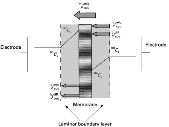
Figure 3 Schematic drawing illustrating concentration profiles of a salt in the boundary layer on both sides of an ion exchange membrane and the fluxes of cations and anions in the boundary layer and the membrane surface. For abbreviations, see Table 1.
of the bulk solutions, the concentration gradients are limited to a relatively thin laminar boundary layer at the membrane surfaces, as indicated in Figure 3, which shows the salt concentration proRles in the solutions near the surface of an anion exchange membrane.
The concentration proRles at the membrane surface can be determined by a mass balance based on the so-called Nernst Rlm model, which assumes static boundary layers at the membrane surfaces, where con-centration and electrical potential gradients perpen-dicular to the membrane surfaces are the only driving forces for the mass transport. The bulk solution be-tween the laminar boundary layer is well mixed and has a uniform concentration. It can be assumed that the transport of ions through an ion exchange mem-brane is the result of migration caused only by an electrical potential gradient, while in the solution ions are transported by both migration and diffusion. In a steady state the ionSux through the membrane is identical to that through the boundary layer. For a strictly permselective membrane it is given by:
mJmigcou"!bJmigcou#bJdiffcou"tm cou
i F"t
b cou
i F!Ds
dCs
dz [21]
The current density can be obtained from eqn [21] by integration over the boundary layer. For the boundary layer at the membrane surfaces adjacent to the diluate the current density is:
i"! FDs
(tmcou!t cou)
bdCs!mdC s
z [22]
When the hydrodynamicSow conditions are kept constant the boundary layer thickness, z, will be constant and the current will reach a maximum value independent of the electrical potential gradient if the salt concentration at the membrane surface, mdC
s,
becomes 0. This maximum current is referred to as the limiting current density,ilim, which is given by:
ilim"! FDs
(tmcou!t cou)
bdC s
z [23]
Exceeding the limiting current density in practical applications of electrodialysis can affect the ef-Rciency of the process severely by increasing the elec-trical resistance of the solution and by causing water splitting, which leads to changes in the pH values of the solutions, causing precipitation of metal hydrox-ides on the membrane surface.
Electrodialysis Process and
Equipment Design
The performance of electrodialysis in practical ap-plications is not only a function of membrane proper-ties but is also determined by the membrane stack and the overall process design.
Electrodialysis Stack Design
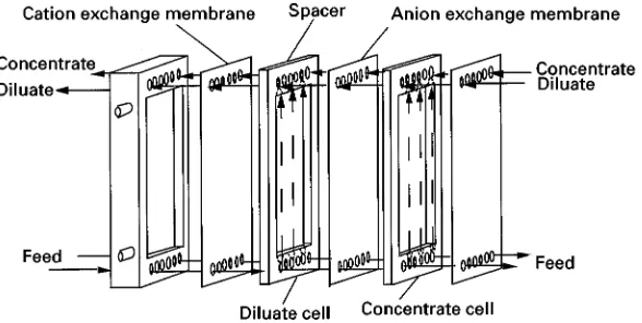
Figure 4 Exploded view of an electrodialysis stack arrangement, indicating the individual cells and the sheet flow-type spacer, also containing the manifolds for distribution of different flow streams.
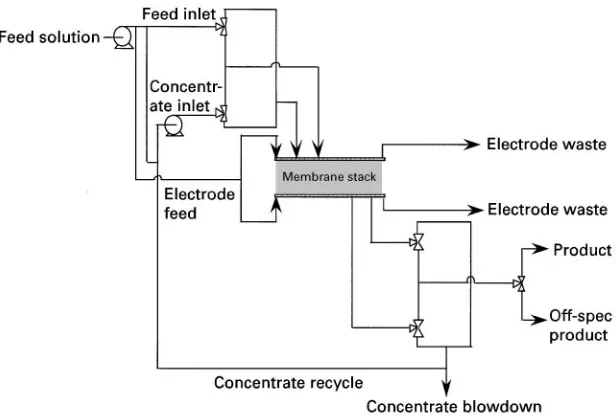
Figure 5 Flow scheme of the unidirectional electrodialysis operating mode.
Figure 4. The membranes are stacked between electrodes in such a way that the Sow streams are kept separate. The gaskets that separate the mem-branes contain manifolds to distribute the process Suids to the different compartments. The supply ducts for the diluate and the concentrate are formed by matching holes in the gaskets, in the membranes, and in the electrode cells. To minimize the resis-tance of the aqueous solution, the disresis-tance between the membrane sheets is made as small as possible and is normally between 0.5 and 2 mm in industrial electrodialysis stacks. In an industrial electro-dialysis system, 200}1000 cation and anion exchange membranes are installed in parallel to form an electrodialysis stack with 100}500 cell pairs. Spacers between the individual membrane sheets sup-port the membranes and provide mixing of the Sow streams.
A proper electrodialysis stack design provides the maximum effective membrane area per unit stack volume and ensures uniform Sow distribution
through each compartment. The spacer screen should provide a maximum of mixing of the solutions at the membrane surfaces to reduce concentration polariza-tion, but the pressure loss must be small.
Process Design and Modes of Operation
The efRciency of electrodialysis in a given ap-plication depends greatly on the process, design and mode of operation. Two different operating modes are currently used: theRrst is referred to as unidirectional electrodialysis and the second as elec-trodialysis reversal.
Figure 6 Flow scheme of the electrodialysis reversal operating mode.
does not contain chloride ions. Unidirectionally oper-ated electrodialysis plants are rather sensitive to membrane fouling and scaling and often require care-ful feed solution pretreatment and stack-cleaning procedures.
Membrane fouling and scaling can be greatly re-duced by operating in the electrodialysis reversal mode. In this operating mode, the polarity of the current is changed periodically every few minutes to a few hours. Simultaneously, the hydraulic Sow streams are reversed, as shown inFigure 6. The ad-vantage of the electrodialysis reversal operating mode is that precipitates that are formed the concentrate cells are redissolved when the Sow is reversed and these cells become the diluate cells. In the elec-trodialysis reversal operating mode there is a brief period when the concentration of the desalted prod-uct does not meet the prodprod-uct quality speciRcation. Thus, a certain amount of the product will be lost to the waste stream.
Electrodialysis Process Costs
The economics of an electrodialysis process are usu-ally expressed as cost per unit product. These costs are the sum ofRxed charges associated with amorti-zation of the investment and operating costs such as energy and labour.
Investment costs include items such as the electrodialysis stacks, pumps, electrical equip-ment and membranes and are proportional to the required membrane area. The minimum required membrane area for a certain plant capacity is
given by:
A"zFQCn
i [24]
The required membrane area for a given capacity electrodialysis plant is proportional to the amount of ions removed from a given feed solution and inversely proportional to the applied current density.
As indicated earlier, the applied current density should not exceed a certain limiting value. According to eqn [23] this value is proportional to the diluate concentration and the mass transfer in the boundary layers at the membrane surfaces. The mass transfer depends on the boundary layer thickness, which is a function ofSow velocity. For given stack and feed solution properties, the limiting current density is given by:
ilim"bdC
aub [25] Here a and b are constants, the values of which are determined by a series of parameters such as the cell and spacer geometry, the solution viscosity and the transference numbers of ions in the membrane and the solution.
Figure 7 Membrane, energy and total costs of the actual desalination process in electrodialysis.
given by:
iMlim"bdCM
saub"aub
bdCos!bdCp s
log
bdCo
bdCp s
[26]
Combining eqns [24] and [26] leads to:
Amin"a log
bdCo s bdCp s bdCos!bdCp
s
[27]
The constant a is determined by the feed Sow vel-ocity, the stack design, etc.
The operating costs of an electrodialysis plant are mainly determined by the energy consumption which is the sum of the electrical energy required for the ion transfer and the energy necessary for pumping the solution through the stack, as indicated in eqns [17] and [18]. The energy required for the desalting pro-cess is a function of the feed solution concentration. The pumping energy depends on theSow velocities in the stack.
It should be noted that, according to eqn [12], the energy costs increase with increasing current density, while the required membrane area decreases with increasing current density. Thus the total desali-nation cost } which is the sum of capital, energy and operating costs}will reach a minimum at a cer-tain current density, as illustrated inFigure 7, where the total cost of an electrodialysis process is shown schematically as a function of the applied current density.
Applications of Electrodialysis
Electrodialysis is mainly used to desalinate saline solutions such as brackish water. But other applica-tions such as the treatment of industrial efSuents, demineralization of whey and deacidiRcation of fruit
juices are becoming increasingly important. In Japan, electrodialysis is also used in the production of table salt from sea water.
Desalination of Brackish Water by Electrodialysis
In terms of installed plant capacity, the most impor-tant application of electrodialysis is the production of potable water from brackish water. Here, elec-trodialysis competes directly with reverse osmosis and multistage Sash evaporation. For water with a relatively low salt concentration (less than 5000 p.p.m.), electrodialysis is generally considered to be the cheapest process. Another signiRcant feature of electrodialysis is that salts can be concentrated to comparatively high values without affecting the economics of the process severely.
Production of Table Salt
In the production of table salt from sea water, electrodialysis is used to concentrate sodium chloride up to 200 g L\1 prior to evaporation.
This application is developed and used nearly exclus-ively in Japan. Key to the success of electrodialysis in this application has been the development of mem-branes with a preferred permeability of monovalent ions.
Electrodialysis in Waste Water Treatment
Treatment of metal ion-contaminated rinse waters produced in electroplating operations is an important application of electrodialysis. Complete recycling of the water and the metal ions can be achieved in favourable cases. A disadvantage, however, is that in electrodialysis only ions can be removed from a feed stream. Uncharged components that are also present in the rinse waters cannot be recovered.
Dump leach waters containing heavy metal ions have also been successfully treated by electrodialysis. The removal of nitrate from drinking water by elec-trodialysis is an application that seems to be competitive to processes such as ion exchange or reverse osmosis.
While in most of these applications the average plant capacity is considerably lower than that in brackish water desalination or table salt production, there is also a signiRcant number of large plants installed for the treatment of reRnery efSuents and cooling-tower waste streams.
Concentration of Reverse Osmosis Brines
concentration, however, may be achieved at reason-able cost by electrodialysis.
Electrodialysis in the Food and Chemical Industry
Several applications of electrodialysis in the food in-dustries, such as the demineralization of cheese whey, have considerable economic signiRcance and are well established today. Other applications, such as the deashing of molasses or de-acidiRcation of fruit juices, are still in an experimental stage. In the chem-ical industry electrodialysis is used for the desalina-tion of protein, dextran or sugar soludesalina-tions. Here, electrodialysis is often in competition with other sep-aration procedures such as dialysis and solvent extraction. The separation of organic acids is an ap-plication of electrodialysis that is of interest to the pharmaceutical industry.
Production of Ultra Pure Water
Electrodialysis is now being used for the production of ultra pure water for the semiconductor industry. By combining electrodialysis with mixed-bed ion ex-change resins, deionized water is obtained without a chemical regeneration of the ion exchange resin. The process has been commercialized recently.
Conclusions
Electrodialysis has a long and proven history in the desalination of brackish waters. However, new applications in waste water treatment as well as in the
food and the chemical industry are becoming more and more important. There are still a multitude of problems to be solved. Some are related to the proper-ties of the membranes and the process design, while others are caused by the lack of application know-how and practical experience.
Further Reading
Bergsma F and Kruissink ChA (1961) Ion-exchange mem-branes.Fortschrifte in der Hochpolymer-Forschung21: 307}362.
Helfferich F (1962) Ion-Exchange. London: McGraw-Hill.
Katz WE (1979) The electrodialysis reversal (EDR) process.
Desalination28: 31}40.
Lacey RE (1972) Basis of electromembrane processes. In: Lacey RE and Loeb S (eds)Industrial Processing with Membranes. New York: John Wiley.
Nishiwaki T (1972) Concentration of electrolytes prior to evaporation with an electromembrane process. In: Lacey RE and Loeb S (eds)Industrial Processing with Mem-branes. New York: John Wiley.
Schaffer LH and Mintz MS (1966) Electrodialysis. In: Spiegler KS (ed.)Principles of Desalination, pp. 3}20. New York: Academic Press.
Spiegler KS (1956) Electrochemical operations. In: Nachod FC and Schubert J (eds) Ion Exchange Technology, pp. 118}181. New York: Academic Press.
Strathmann H (1995) Electrodialysis and related processes. In: Nobel RD and Stern SA (eds)Membrane Separation Technology, pp. 213}281. Amsterdam: Elsevier. Wilson JR (1960) Design and operation of electrodialysis
plants. In: Wilson JR (ed.) Demineralization by Elec-trodialysis. London: Butterworth.
Filtration
R. Sahai, EuTech Scientific Services, Morganville, NJ, USA
Copyright^ 2000 Academic Press
Introduction
Filtration is a key processing operation in the pharma-ceutical, chemical and cosmetic industries. For example, Rltration may be necessary to clear process solutions before analysis or as process step in manufac-turing or in the sterilization of process solutions. Ana-lytical testing requires only laboratory-scale Rltration and is usually performed by a variety of membrane types depending upon the application. Filtration in manufacturing requires large-scale Rltering in engin-eered devices called membrane modules or cartridges.
Filtration Mechanism
Filtration is a mechanical phenomenon, which is sometimes aided by chemical manipulations of the Rltration medium to make it more efRcient. In any case, a driving force across the Rlter media is required. The following methods can be used to gen-erate this driving force:
E Vacuum
E Pressure difference E Centrifugal force E Gravity pull
E Concentration difference E Electrical potential difference E Temperature difference