1
Sensitivity Analysis of Active Flow Control Systems:
Operating Parameters and Configuration Design
Mark Jabbal
*and Valerio Tomasso
†Brunel University, London UB8 3PH, United Kingdom
Nomenclature
D = distribution diameter
d = orifice diameter
h = height of induced plasma velocity profile
lx = streamwise length of plasma electrode
ly = spanwise length of plasma electrode
m = mass
m
ɺ
= mass flow ratemW = power specific mass
g
w
m
ɺ
= power-specific fuel consumptionn = number of actuators
p0 = total pressure
pplenum = plenum differential pressure
R = universal gas constant
sA = spanwise extent of actuator array
T = temperature
t = time of duration
U = velocity
VR = peak jet-to-freestream velocity ratio
W = power
∆ = ratio of orifice diameter to local boundary layer height
δ = boundary layer height
η = efficiency
λ = ratio of actuator spanwise spacing to orifice diameter
ρ = density
τ = pulse duty cycle subscripts
E = electric
F = fluidic
∞ = freestream
I.
Introduction
Aerodynamic gains offered by active flow control (AFC) can be maximized if AFC system design is included
as part of the initial aircraft optimization process. In the more likely scenario where inception of AFC systems
is initially via retrofitting to existing aircraft platforms, implementation will largely be dictated by whether such
*
Lecturer, School of Engineering and Design, Kingston Lane, Uxbridge. Corresponding author, Email: [email protected]
2
systems can be installed within the available mass, power and space constraints. Research has been
undertaken to understand the nature of systems architectures needed to support the generation, management,
and distribution of power to AFC actuators for application on commercial transport aircraft1. The motivation for
this study is to understand how current AFC systems meet the constraints imposed by an A320 aircraft and
the extent to which variations in system configuration, operating parameters and efficiency affect overall
system mass and power consumption.
There is still considerable uncertainty with regards to AFC system design for compliance with aircraft
constraints. Consider the example of fluidic actuators, which can take the form of pulsed jets2, vortex
generating jets3 or sweeping jets4, and which can be used for separation control applications in off-design
flight conditions. Power to the actuators can be supplied pneumatically via direct engine bleed or electrically
and pneumatically via electrical air compressors (referred to hereon as the ‘hybrid’ system architecture1). The
choice between distributing power electrically or pneumatically is however still an open question. Furthermore,
there is the choice of whether a centralized compressor or a series of localized compressors should be
utilized for the hybrid system, in addition to actuator operating parameters that satisfy performance and
system requirements. For cruise flight, plasma actuators have been proposed for skin friction drag reduction
applications5 as part an ‘electro-fluidic’ system architecture1. Current actuator efficiency of dielectric barrier
discharge (DBD) plasmas is however very low, typically 0.1%5 (based on the conversion of electrical input
power to ‘mechanical’ output power, namely induced kinetic energy density flow rate measured from local
velocity profiles), with the consequence of excessively high system mass and power costs1. Thus, it is useful
to know the gains in efficiency that will make implementation viable.
Within the present work it is proposed that the sensitivity analyses conducted against the backdrop of
applicable design trades and existing A320 system hardware data1, will show the extent to which aircraft
constraints can be met, as well as inform the wider flow control community on viable strategies for AFC
systems implementation and targeted improvements in actuator efficiency.
II. Research Methodology
3
The present work uses a scalable, low-order system mass model1, as defined in Eq. (1).
(1)
The overall system mass, m, is equal to sum of the AFC system hardware masses and the mass cost of the
energy used by the system. The former is made up of scalable power specific mass terms, mw, for each of the
generation, management, distribution and actuation subsystems that constitute to the systems architecture;
whereas the latter is the mass of the fuel used for the duration of AFC operation and is determined from the
power-specific fuel consumption of the generator system,
m
ɺ
w
g. Both mw andm
ɺ
w
g have units of kg/kW andare multiplied in Eq. (1) by the overall system power consumption, WE (equivalent to the fluidic output power
from an array of AFC actuators, WF, divided by overall power efficiency of the system,η) to give the overall
system mass. Commercial, aerospace-specific data for pneumatic ducts‡ and electric wires§ are used to
compare the relative benefits of distributing power pneumatically and electrically, and subsequently added to
Eq. (1) in the form of a distribution mw term for a given AFC application.
The constraint for AFC system mass in this study is provided by Airbus UK design trades, which indicates that
for a 1% overall drag reduction delivered by an AFC system to an A320 aircraft, maximum AFC system mass
permitted is 250kg (~0.4% of Operating Empty Weight, OEW)**. Thus, it is assumed that each AFC system
considered is capable of delivering the stated drag reduction within the mass limit. Available power for the
AFC system is limited by the number of engine integrated drive generators (IDG); for the A320 there are two
IDGs which deliver 90kW each. It is also assumed that the largest duct/cable diameter permitted is that which
can be accommodated in the A320 wing leading edge; i.e. approximately 50mm1. All other A320 related
systems, including AFC power generation and management subsystems have been previously documented1.
B. Data Reduction
1. Hybrid System Architecture
Utilization of the hybrid system architecture with pulsed-air jet actuators2 can make use of a centralized or
decentralized compressor configuration, as illustrated in Figure 1. The centralized configuration uses a
‡Data available online at:http://flexfab.com/wp-content/uploads/2012/12/Dist-Catalog-12-21-12.pdf
[retrieved 6 Jun. 2013].
§
Data available online at: http://www.wirefacts.com/MIL-W-2275934.php[retrieved 4 Sep. 2012].
**Private communication, Airbus Operations Ltd, 2010.
[
m
m
t
]
W
m
F w Wgɺ
+
Σ
=
(
η
)
4
scale compressor, whereas the decentralized configuration uses meso- or micro-scale compressors. Each
configuration was compared for LE slat separation control application, of which the actuator implementation
parameters are shown in Table 1. Based on compressor mass, power rating and efficiency, mW terms are
obtained for each configuration for input in Eq. (1) to deduce system costs. Furthermore, individual
compressor mass flow rate is compared against total mass flow rate requirement (Table 1) to deduce the
number of actuators per compressor:
1) Micro-scale (8mm; 0.36g/s; ~5% efficiency)6 – mW=18.2kg/kW; 17 actuators per compressor
2) Meso-scale (25mm; 2.4g/s; ~50% efficiency)7 – mW=1.82kg/kW; 115 actuators per compressor
3) Macro-scale (200mm; 53g/s; ~85% efficiency)1 – mW=1.07kg/kW; 2530 actuators per compressor
a) Macro-scale compressor system
b) Meso-scale compressor system
5
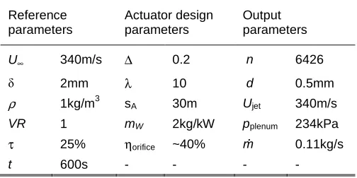
Table 1 Air-jet actuator implementation parameters for LE slat separation control
Reference parameters Actuator design parameters Output parameters
U∞ 340m/s ∆ 0.2 n 6426
δ 2mm λ 10 d 0.5mm
ρ 1kg/m3 sA 30m Ujet 340m/s
VR 1 mW 2kg/kW pplenum 234kPa
τ 25% ηorifice ~40% ṁ 0.11kg/s
t 600s - - - -
To examine actuator parameter sensitivity on hybrid system mass, power consumption and distribution
diameter requirements, velocity ratio, VR, and pulse duty cycle, τ were varied. VR represents the ratio of
actuator peak exit velocity to local freestream velocity and τ is defined as the ratio between the time the
actuator is on and off. These two parameters dictate total fluid power delivered by an actuator array1, as
shown in Eq. (2)
(2)
Duct diameter sizing for a given AFC application is determined by the mass flow rate and air-jet plenum
pressure8 (where flow velocity in the duct is limited to Mach 0.2, based on safe industrial practice to mitigate
against duct fatigue and possible rupture)
(3)
2. Electro-Fluidic System Architecture
To examine actuator efficiency sensitivity on system mass and power consumption, the efficiency term, η was
varied in Eq. (1) under the assumption that the inherently low actuator efficiency (~0.1%) and small variation
in the present study (<1%) was sufficient to render other subsystem efficiencies, which are much larger, as
negligible. The study was conducted for skin friction drag reduction application along the wing main element,
with implementation parameters shown in Table 2.
3 3
2
1
)
(
4
∞∆
=
VR
s
U
W
Fρ
Aδ
λ
π
τ
)
(
4
0p
p
U
RT
m
D
plenum+
6
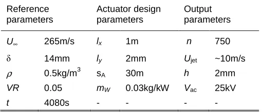
Table 2 DBDplasma actuator implementation parameters for main element skin friction drag reduction
Reference parameters Actuator design parameters Output parameters
U∞ 265m/s lx 1m n 750
δ 14mm ly 2mm Ujet ~10m/s
ρ 0.5kg/m3 sA 30m h 2mm
VR 0.05 mW 0.03kg/kW Vac 25kV
t 4080s - - - -
A 1m chordwise electrode length corresponds to 30% wing area coverage. The output power of plasma
actuators1 for local fluid acceleration is given by Eq. (4) and is used in Eq. (1) to determine system costs
(4)
III. Results
A.
Distribution Systems: Comparison of Pneumatic and Electric Power Distribution
Methods
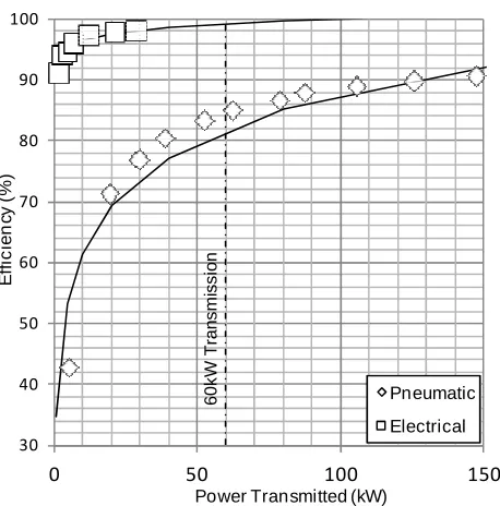
Figure 2 compares power specific mass, distribution diameter and efficiency as a function of power
transmission for electric and pneumatic distribution in a wire and duct respectively. Below 20kW, distribution
power specific mass, diameter and efficiency are all markedly lower for electric distribution. Above 20kW,
power specific mass is lower for pneumatic distribution, although in practice it would be more mass efficient to
transmit high electrical power through a bundle of smaller cables than a single, large one due to insulation and
heat transfer issues. Mass and efficiency progressively increase for pneumatic distribution at high power,
however duct diameter is limited at 50mm (corresponding to 60kW transmission) by internal wing constraints.
Electric distribution is therefore the only viable option above 60kW. Thus from a practical perspective, there is
clear benefit to utilizing electrical power distribution as the basis for AFC implementation on aircraft.
3 3
)
(
6
1
∞=
U
l
l
h
s
VR
W
y x A7
a) Distribution power specific mass per unit length
b) Power distribution diameter
P
o
w
e
r
S
p
e
c
if
ic
M
a
s
s
p
e
r
U
n
it
L
e
n
g
th
(
K
g
/k
W
m
8
30 40 50 60 70 80 90 1000 50 100 150
E ff ic ie n cy ( % )
Power Transmitted (kW)
Pneumatic
Electrical
c) Power distribution efficiency
Fig. 2 Variation of power distribution characteristics with power transmission
B.
Generation Systems: Comparison of Micro-, Meso- and Macro-scale
Compressor Configurations on the Hybrid System Architecture
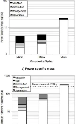
Comparison of power specific mass for the hybrid AFC system architecture with micro-, meso- and
macro-scale compressor arrangements is shown in Fig. 3a. The power specific mass for the micro compressor
configuration is approximately 20kg/kW; i.e. 20kg of system hardware required for 1kW of power flow through
that system. This is relatively high compared to both the meso and macro configurations (~4kg/kW) and is due
to the inherently low compressor efficiency (~5%). Consequently, over 85% of the system mass in the micro
[image:8.595.181.410.73.305.2]compressor configuration is required in power generation.
Figure 3b compares absolute system mass of each configuration for LE slat separation control (Table 1). The
high system cost of the micro compressor configuration is confirmed with an overall mass which exceeds
constraints by 75kg. Both meso- and macro-scale configurations each have a system mass under the
constraint, with the former approximately 13kg greater than the latter. From a practical perspective however,
this small mass penalty may be offset by the potentially wider benefits of the meso-scale configuration. The
macro-scale configuration features a relatively large (200mm diameter) centralized compressor with a 22mm
diameter main duct supplying air to the actuators (Fig. 1a). This is in contrast to the meso-scale configuration
9
featuring multiple compressors (25mm diameter) with 3mm diameter ducts feeding the actuators (Fig. 1b) and
which therefore has a smaller form factor conducive for aircraft implementation. The decentralized nature of
the meso-scale configuration also ensures that potential compressor failure will remain localized, thus
minimizing significant loss in overall AFC performance.
a) Power specific mass
[image:9.595.170.424.191.606.2]
b) System mass
Fig. 3 Comparison of relative subsystem and absolute architecture system mass for macro-, meso- and micro-scale compressor configurations.
10
C.
Actuator Systems: Parameter Sensitivity of Air-jet Actuators on the Hybrid
System Architecture
The effect of jet-to-freestream velocity ratio, VR and pulse duty cycle, τ on the hybrid AFC system architecture
mass, power consumption and distribution diameter are shown in Fig. 4. Results presented are based on the
macro compressor configuration for the application defined in
§
B.1. In Fig. 4a, the magnitude of system massincreases with both VR and τ, with the rate of increase greater for VR, in accordance with Eq. (2). At τ=100%,
i.e. steady blowing, system mass drops as the need for an actuator pulse valve system and its associated
electrical supply becomes redundant and hence is omitted. Use of fluidically pulsed jets such as sweeping jet
actuators4 would eliminate valves completely and thus reduce mass requirements. The system remains below
the mass limit when operated at VR=0.5 and 1.0 for all values of τ, but exceeds the limit when operating at
VR=1.5 for τ>30%. Similar trends are observed with system power consumption (Fig. 4b), with power
constraint from a single IDG exceeded at VR=1.5 for τ>50% and maximum power constraint (two IDGs)
exceeded for VR=1.5 for τ>90%.
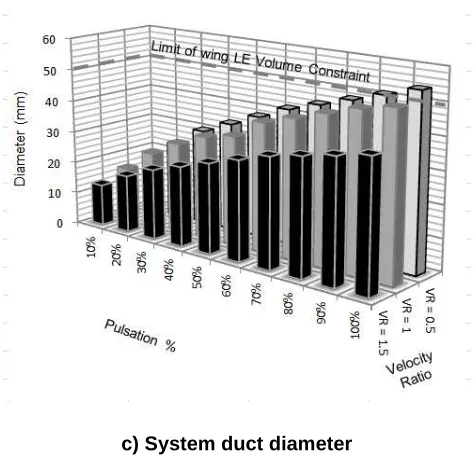
Contrary to the trends shown in system mass and power consumption, it is observed in Fig. 4c that duct
diameter is inversely proportional to VR and directly proportional to τ. This is due to the relation defined in Eq.
(3). Diameter constraint is only exceeded for steady blowing conditions at VR=0.5.
In a practical context, a hybrid system designed to operate air-jet actuators at VR=1 offers the most versatility
by permitting operation across the full range of τ without exceeding mass and power constraints associated
with higher VR operation, or duct diameter constraint for lower VR operation. It also suggests that ‘brute force’
techniques9 for separation control with VR>>1 (i.e. tangential blowing) are not suitable for aircraft
implementation via the hybrid architecture, unless utilized for smaller areas of application or are capable of
11
a) System mass12
[image:12.595.179.417.66.294.2]c) System duct diameter
Fig. 4 Variation of hybrid architecture systems costs with air-jet actuator operational parameters
D.
Actuator Systems: Efficiency Sensitivity of DBD Plasma Actuators on the
Electro-fluidic System Architecture
The effect of plasma actuator efficiency on system power consumption and mass of the electro-fluidic AFC
architecture is presented in Fig. 5 for wing main element skin friction drag reduction (Table 2). Based on
current actuator efficiency5 ~0.1%, power consumption and mass exceed constraints by 110kW and 180kg
respectively. To satisfy maximum power constraints for the same chordwise electrode length, actuator
efficiency should be increased to 0.16%, which equates to a system mass also just within the maximum limit.
A threefold increase in efficiency to 0.32% would lower power consumption to that producible by a single IDG,
13
a) System power consumption
[image:13.595.175.418.69.315.2]b) System mass
14
IV. Conclusions
This paper has outlined sensitivity analyses for AFC systems architectures to understand how the method of
power distribution, compressor scale for power generation, and actuator operational parameters and
efficiency affect overall system mass and power consumption. The work was conducted with an existing AFC
system mass model1 applied to an A320 aircraft under consideration of relevant AFC design trades and
engineering constraints.
The major findings of this study are summarized as follows:
1) For power transmission <20kW, electrical power distribution is more efficient than pneumatic power
distribution (less by a factor of 2 at 5kW) and more cost effective in mass and diameter/space constraints
(less by a factor of 4 and 5 respectively at 5kW). For power transmission >20kW, pneumatic distribution is
more competitive in mass (less by a factor of 3.5 at 50kW), but becomes impractical above 60kW as duct
diameter exceeds the physical constraint of the wing leading edge volume. These observations suggest
that AFC systems architectures should be based on electrical power distribution, with the implication of
utilizing electrically-powered AFC actuators or in the case of fluidic actuators, electrically-powered air
compressors (‘hybrid’ system) rather than direct engine bleed.
2) The hybrid AFC architecture, incorporating air-jet actuators with electrically-powered compressors, shows
that for LE slat separation control the micro-scale compressor configuration exceeds maximum permitted
system mass by 75kg. Both meso-scale and macro-scale compressor configurations satisfy mass
constraints, with the former approximately 13kg greater than the latter. However the greater practicalities
conferred by the meso-scale compressor configuration, such as a smaller form factor, fault isolation and
smaller consequence of compressor failure, make it the most viable strategy for hybrid AFC
implementation.
3) Operational parameter sensitivity of air-jet actuators on the hybrid AFC architecture shows that system
mass and power consumption are proportional to both jet-to-freestream velocity ratio (VR) and pulse duty
cycle (τ), whereas distribution diameter is inversely proportional to VR. For the range of VR (0.5, 1.0, 1.5)
and τ (10%-100%) investigated for LE slat separation control, system mass and power constraints (based
15
4) For the electro-fluidic AFC architecture incorporating a DBD plasma actuator array along the wing main
element with 1m chordwise electrode length, system mass and power constraints are exceeded by 180kg
and 110kW respectively based on current actuator efficiency (0.1%). To make the AFC system compliant
with mass and maximum power constraints (based on total IDG output) for the same chordwise length,
actuator efficiency needs to be increased to 0.16%. A threefold improvement in plasma efficiency (0.32%)
would make the AFC system compliant with single IDG output power constraint, while affording a reduced
mass (120kg below mass constraint).
The above results should be placed in the context that actuators and micro/meso-scale compressors are still
under research and development and that the prospect of further gains in performance can be expected,
which will lead to lower overall systems weight and thus greater viability for aircraft integration. From the
results of this study the authors anticipate that the application of fluidic actuators as part of a decentralized
compressor system for separation control to be a realizable goal in the near term, whereas the application of
plasma actuators for viscous drag reduction remains a much longer term goal.
Finally, a note on the AFC systems cost/performance design trade. Whilst drag reduction is a suitable metric
for plasma actuators aimed at long duration (cruise) applications, an alternative metric for fluidic actuators
aimed at short duration (take-off and landing) applications may be more suitable, e.g. permitted systems mass
for percentage of lift enhancement or increase in CLmax. It should also be noted that while larger aircraft will
permit larger AFC systems costs to be incurred, the relationship between AFC system mass and aircraft size
(e.g. OEW) is not a linear one. As such, similar studies for other aircraft should be carried out on a
case-by-case basis using separate design trades.
References
[1] Jabbal, M., Liddle, S.C., and Crowther, W.J., “Active Flow Control Systems Architectures for Civil
Transport Aircraft,” Journal of Aircraft, Vo. 47, No. 6, 2010, pp. 1966-1981.
16
[2] Warsop, C., Hucker, M., Press, A.J., and Dawson, P., “Pulsed-Air Jet Actuators for Flow Separation
Control,” Flow, Turbulence and Combustion, Vol. 78, No. 3-4, 2007, pp. 255-281.
doi: 10.1007/s10494-006-9060-4
[3] Godard, G., Foucaut, J.M. and Stanislas, M., “Control of a Decelerating Boundary Layer. Part 2:
Optimization of Slotted Jet Vortex Generators,” Aerospace Science and Technology, Vol. 10, No. 5,
2006, pp. 394-400.
doi: 10.1016/j.ast.2005.11.006
[4] Woszidlo, R., Raghu, S., and Wygnanski, I., “Parametric Study of Sweeping Jet Actuators for Flow
Separation Control,” AIAA Paper 2010-4247, June 2010.
doi: 10.2514/6.2010-4247
[5] Moreau, E., “Airflow Control by Non-Thermal Plasma Actuators,” Journal of Physics D: Applied Physics,
Vol. 40, Feb. 2007, pp. 605-636.
doi: 10.1088/0022-3727/40/3/S01
[6] Epstein, A., “Millimeter-Scale, Micro-Electro-Mechanical Systems Gas Turbine Engines,” Journal of
Engineering for Gas Turbines and Power, Vol. 126, Apr. 2004, pp. 205-226.
doi:10.1115/1.1739245
[7] Kang, S., “Fabrication of Functional Mesoscopic Ceramic Parts for Micro Gas Turbine Engines,” PhD
Thesis, Stanford University, USA, 2001.
[8] Bray, T.P., and Garry, K.P., “Optimization of Air-Jet Vortex Generators with Respect to System Design
Parameters,” The Aeronautical Journal, Vol. 103, No. 1028, 1999, pp. 475-479.
[9] Warsop, C., “MEMS and Microsystems Technologies – Their Potential and Status for Drag Reduction
and Separation Control,” European Congress on Computational Methods in Applied Science and