doi:10.4236/iim.2010.23028 Published Online April 2010 (http://www.SciRP.org/journal/iim)
Combining a Safety Management Process with a Safety
Framework
Derrick Black1, Elizabeth Hull1, Ken Jackson2 1
School of Computing and Mathematics, University of Ulster, Newtownabbey, UK
2
IBM Ltd., Portsmouth, UK E-mail: [email protected]
Received October 27, 2009; revised February 12, 2010; accepted March 10, 2010
Abstract
A safety document management system, known as a Permit for Work (PFW) system is used commonly in the Power Industry to provide appropriate safety conditions for those working on the generating system. This paper investigates how a safety management process (+PFW) can be combined with a safety framework to enhance system effectiveness to ensure the requirements of users and suppliers can be met. While the paper makes some reference to the power industry, the concept is applicable to the management of systems in other domains.
Keywords:Safety, Permit for Work, Systems Engineering, Power Industry, Health and Safety, Process, Modelling, Framework
1. Introduction
A safety document management system, known as a Permit For Work (PFW) [1,2] system is used commonly in the Power Industry to provide safe working conditions for staff and contractors charged with performing repair tasks on the generating system. The PFW system has until relatively recently been a manual system. Although this method is still capable of performing the required tasks satisfactorily more and more users are operating a computerised information management solution to fa-cilitate the issue and control of the required documents. In the Power Industry, the PFW system is an accepted requirement, but as the Health and Safety Legislation [3] becomes more demanding on other industries, it is also becoming more common in other domains [4].
Research in requirements engineering [5,6] has recog-nized the need to ensure that systems are developed with safety being considered as an integral part of require-ments elicitation. Furthermore, it is generally understood that all stakeholders involved in the requirements process need to be fully conversant with the consequences of their decisions and the potential impact on the domain [7,8].
The Power Generation Industry is not the only sector that has experience of using PFW systems. Oil and Gas producers [9] and the Mining industry all have similar
expertise, although in some instances it is referred to as a ‘Permit to Work’ (PTW) System [10]. Such systems are defined as a formal written approach used to manage certain types of work which are identified as potentially hazardous [9]. As the legal requirements have changed regarding safety, the definition of the term ‘certain types of work’ has been modified. PFW systems are no longer the exclusive domain of the industries that previ-ously were considered dangerous. Rather, they are now a requirement of almost every industrial sector.
Health and Safety leglislation is concerned with either eliminating all risks and hazards or at least minimizing them to a level that is considered as low as reasonably practical. When this is not possible, and significant risks still remain, the HSE guidelines clearly state that an al-ternative method of ensuring the safety of an individual is required. Hence a higher level of control is required and therefore a PFW system is introduced.
D. D. BLACK ET AL. 234
safety is provided for all stakeholders in the maintenance and repair tasks. This is achieved by means of the +PFW process [1,11].
+PFW is a process that can be applied by either the end user of the preferred solution or the supplier of the system. Its implementation will ensure that the users are capable of operating the solution in a safe and appropri-ate manner. The supplier can use the process to deter-mine where the user is, in terms of readiness, to install the system. Health and Safety Executive guidelines [12] are very specific about the need to use a PFW system but they are less clear about how the PFW system should be implemented and what is expected of the end user or supplier of the system. If the guidelines are taken in a literal context, it could be argued that having decided that the risk and hazards cannot be controlled adequately a PFW system must then be operated. Furthermore, pro-vided the paper work issued emanates from a PFW solu-tion, the user has conformed with a correct interpretation of the guidelines. In reality this is a very serious miscon-ception.
Both the end user and the supplier are obliged by health and safety legislation and they must both endeav-our to meet these statutory requirements. The +PFW process provides a mechanism to achieve this goal. However, on its own the +PFW may not be sufficient to establish all the elements required to satisfy these re-quirements and this paper is to attempt to enhance the process to ensure these objectives are fully met.
A brief outline of +PFW is discussed in Section 2, while Section 3 introduces the concept of a framework [1,13] to establish safety requirements. These approaches were derived from different viewpoints of safety but they have the common objective of ensuring that safety is always considered in the development and implementa-tion of a system, particularly a PFW soluimplementa-tion. Secimplementa-tion 4 investigates combining the +PFW process and the Safety Framework so that the required outcomes can be ach- ieved for both the supplier and the end user.
2. The +PFW Process
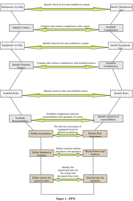
+PFW is an approach which provides a way of ensuring the correct implementation of a PFW system. When a system, which is life safety critical, is implemented and operated, it is important that the users of the solution should be totally conversant with the items addressed by the system [14]. They should be aware of the limitations of the system, understand their responsibilities and know the consequences of any failure to adequately perform the roles and task associated with the system. Figure 1 shows the process diagrammatically.
In following the +PFW process accurately, a situation develops which provides a successful implementation of the chosen solution allowing it to be operated effectively.
It also allows systematic reviews and audits to be per-formed thereby ensuring continued compliance in light of changing circumstances and/or environmental condi-tions.
The three key stages of +PFW are as follows: 1) Establishment of a maintenance list
The initial concern here is to establish the specific items required and the context in which they are required. The outcome should be a definitive list detailing all equipment and plant in the domain that require the issue of safety documents from the process. The assumptions made and the context of the decisions reached must form an integral part of this list. The maintenance list cannot be considered static throughout the lifecycle of the proc-ess, but should be continually reviewed to ensure that it is complete.
2) Development of an equipment list based on the con-text of the maintenance list
To allow work to be undertaken by an individual, items of equipment needing a safety document are idtified. In order to carry out a task, a list of potential en-ergy sources for each item in the maintenance list needs to be established. In this way anything hazardous can be identified and isolated. This new list is an adjunct to the maintenance list described above. The equipment list must be considered as a dynamic document and must reflect the changing environmental conditions of its op-erating environment.
3) Establishment of specified roles
Potential roles for the process need to be identified and their responsibilities assigned appropriately [15] if the required level of safety is to be achieved. Once estab-lished, the roles then need to be allocated to the users of the process.
A full description of the process can be found in [11].
3. Safety Framework
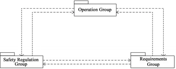
The Safety Framework [1,13] identified three potential groups of views that are common throughout a variety of domains and industries. The interpretation and applica-tion of these view groupings may differ across domains but each can be readily identified in each domain. These provide differing perspectives of a system based on a stakeholder’s concept of the problem. These groups are defined as:-
Operational Group OG. This group contains the views that define the ‘who’ and the ‘what’ of the solution. It identifies what a system is actually required to achieve, who the likely users of a system are, as well as any or-ganisational hierarchy of roles and users that are applica-ble [16].
Identify Maintenance List
Establish Completeness Maintenance List Req
Identify Need for list and establish its content
Compare and contrast completeness with context
Identify Equipment List
Establish Completeness Equipment List Req
Identify Potential Sources
Identify Need for list and establish its content
Compare and contrast completeness with potential sources Identify Context
Identify Roles
Identify operation of responsibilities Establish Roles
Establish Responsibilities
Identify need for roles and establish criteria
Establish completeness between responsibilities and operation of system
Identify the operational rules for
the system and document these rules Define isolation method procedures and operation Provide risk assessment of
equipment based on
defined assumptions Perform Risk
Assessment Define Assumptions
Record Source and Isolation Define Metphod of
Isolation
Develop rules for operation Define context for
operation rules
[image:3.595.82.516.69.721.2]D. D. BLACK ET AL. 236
stakeholders. It includes existing and proposed legisla-tive requirements as well as the accepted industry stan-dards in force in the chosen environment.
Requirements Group RG. This group contains the views which detail the requirements of a system under consideration.
The interrelationship and interdependency of these groupings mirrors the safety aspects of a system. Without accurately and faithfully considering all potential views on a system safety cannot be assured.
Therefore to provide the correct level of assuredness about the safety of a system all views must be identified and their requirements addressed in the framework. Fig-ure 2 shows the relationship between these view groups. A fuller description of the Safety Framework is given [13].
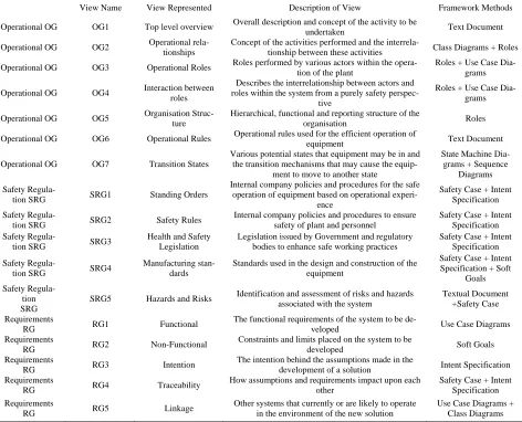
Each of these identified groups were individually in-vestigated and broken down into their component parts to ensure that all aspects of the requirements elicitation were addressed. The Safety Framework is shown in Table 1.
All of the views identified in Table 1 are mapped to a column called the ‘framework methods’. This column shows what might be the most appropriate method or technique to use to accurately represent the identified view.
4. Enhancing the Safety Framework Using
+PFW
The Safety Framework was developed to establish the requirements of a system including its safety aspects. It identified specific areas that need to be included and the models that could be used to represent these require-ments.
However, when a system includes a requirement to operate a PFW system this may complicate the process, particularly when the stakeholders involved have little or no concept of a PFW system. Hence the Safety Frame-work needs to incorporate a method for dealing with this situation.
4.1.Linking the Safety Framework and +PFW
View OG1 in the Safety Framework identified the need to have a textual overview of the system. The overview must include all aspects of the system including any spe-cialist information such as the maintenance and equip-ment list identified in +PFW, while view OG3 estab-lished the requirement to identify the roles required to operate a system. Again the roles identified must include all roles including any that may be specific to a PFW system if such an element is part of the overall solution. Thus these two views clearly indicate the need to link the framework and the process. However, unless the stake-holder understands the concept of a PFW system it is not obvious from the Safety Framework that these items are required.
The need to establish the context of a system and the rationale behind the decision making process are also key components of the Safety Framework. If a PFW system is an element in the overall system it is vital that the requirements for this system are included in the elicitation process. If it is overlooked or ignored, for any reason, then the accurate modelling of the system will not be achieved. Therefore the Safety Framework must encourage users to explore the potential need for a PFW system.
[image:4.595.144.453.581.702.2]The Safety Framework was established by examining the views that should exist in all systems. The views identified were associated with a set of groupings and the methods and techniques required to capture the required information appropriately were established. It is thus in the context of the views that the concerns over the inclu-sion of a PFW system needs to be addressed. The valida-tion carried out clearly indicated that the Safety Framework was sufficiently robust to cope with the inclusion of a PFW system as an element within the overall system, since several of the views discussed in-cluded the PFW system and no issues were evident in terms of the framework’s ability to cope with the full system. It would therefore appear appropriate to include the PFW view, and in consequence +PFW as the model for this view, within the framework. However, this as-
Table 1. Safety framework.
View Name View Represented Description of View Framework Methods
Operational OG OG1 Top level overview Overall description and concept of the activity to be
undertaken Text Document
Operational OG OG2 Operational
rela-tionships
Concept of the activities performed and the
interrela-tionship between these activities Class Diagrams + Roles
Operational OG OG3 Operational Roles Roles performed by various actors within the
opera-tion of the plant
Roles + Use Case Dia-grams
Operational OG OG4 Interaction between
roles
Describes the interrelationship between actors and roles within the system from a purely safety
perspec-tive
Roles + Use Case Dia-grams
Operational OG OG5 Organisation
Struc-ture
Hierarchical, functional and reporting structure of the
organisation Roles
Operational OG OG6 Operational Rules Operational rules used for the efficient operation of
equipment Text Document
Operational OG OG7 Transition States
Various potential states that equipment may be in and the transition mechanisms that may cause the
equip-ment to move to another state
State Machine Dia-grams + Sequence
Diagrams Safety
Regula-tion SRG SRG1 Standing Orders
Internal company policies and procedures for the safe operation of equipment based on operational
experi-ence
Safety Case + Intent Specification Safety
Regula-tion SRG SRG2 Safety Rules
Internal company policies and procedures to ensure safety of plant and personnel
Safety Case + Intent Specification Safety
Regula-tion SRG SRG3
Health and Safety Legislation
Legislation issued by Government and regulatory bodies to enhance safe working practices
Safety Case + Intent Specification
Safety
Regula-tion SRG SRG4
Manufacturing stan-dards
Standards used in the design and construction of the equipment
Safety Case + Intent Specification + Soft
Goals Safety
Regula-tion SRG
SRG5 Hazards and Risks Identification and assessment of risks and hazards associated with the system
Textual Document +Safety Case Requirements
RG RG1 Functional
The functional requirements of the system to be
de-veloped Use Case Diagrams
Requirements
RG RG2 Non-Functional
Constraints and limits placed on the system to be
developed Soft Goals
Requirements
RG RG3 Intention
The intention behind the assumptions made in the
development of a solution Intent Specification
Requirements
RG RG4 Traceability
How assumptions and requirements impact upon each other
Safety Case + Intent Specification Requirements
RG RG5 Linkage
Other systems that currently or are likely to operate in the environment of the new solution
Use Case Diagrams + Class Diagrams
sumption needs to be evaluated further.
The Safety Framework clearly posses sufficient views to represent all the safety aspects of a system including those covered by a PFW system. If this was not the case it would have been obvious that there is something missing from the Safety Framework during the verifica-tion process. Therefore the requirement to incorporate an additional view to deal specifically with the PFW sce-nario seems to be superfluous. However, if it is omitted then the issue of the Safety Framework being used by inexperienced users is not addressed, therefore its inclu-sion provides a method of dealing with this requirement.
4.2. Including +PFW in the Safety Framework
As already discussed, the need to utilize +PFW will not be a requirement of every system. Rather, it is an adjunct only if the system under consideration requires the in-corporation of a PFW system as part of the overall solu-tion. Therefore some method is required that provides the
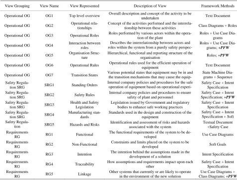
users the ability to utilise +PFW in conjunction with the Safety Framework when it is required. As a minimum the stakeholder needs to be aware of the potential of re-quiring a PFW system and they should at least have the opportunity to reject this element. Instead of including the PFW process as a view within the Safety Framework perhaps a more appropriate solution is to include +PFW as a model in the framework. Several relevant views have been identified within the Safety Framework which need to incorporate +PFW in order to provide an accurate and appropriate representation of any system being reviewed. These can be identified as views OG4, OG5, OG7, SG2 and RG5.
D. D. BLACK ET AL. 238
control of safety using a safety document system and as a result +PFW should be included as a method for this view. View SG2 deals with the safety rules applicable to the system. If these include the operation of a safety document management system then +PFW is a require-ment that should be included as a method within this particular view. The final view affected by +PFW is the RG5 view. This view reflects the linkage between the system being considered and any other systems in the environment. This must include any sub-systems such as a PFW solution that may impact on the overall solution. Therefore it is appropriate to include +PFW as a method for this view.
The enhanced Safety Framework is shown in Table 2, showing the addition of +PFW as an additional method.
5. Enhancing +PFW Using the Safety
Framework
+PFW process provides a clear and concise means of implementing a safety document system which is avail-able to use by stakeholders who are aware of their re-sponsibilities and their impact on others. It provides a mechanism to audit the safety document process to en-sure compliance with the relevant documentation and procedures. It also facilitates reviews of the operation of the PFW system to comply with changing environmental conditions.
5.1. Linkage of Lists in +PFW to the Safety Framework
+PFW is explicit in the need to develop a maintenance list as the first element in the successful implementation and operation of a safety document management system. It consists of the electrical, mechanical and ancillary de-vices and equipment items that are considered to have a significant risk factor in the environment in which the maintenance list is considered. Thus the need to create a list, and to record the context in which it is constructed, are key elements in the process.
However, as the Safety Framework clearly states there is more to the capture of requirements than just knowing that they exist. +PFW is implicit about creating a textual document to record the items that constitute the maintenance list. This is implied by the fact that it is termed a maintenance list and the majority of lists are held in a textual format, but no formal definition of the method of capturing the list is actually provided by the process. The view OG1 identified in the Safety Frame-work requires the stakeholders to textually document the overview of the system. This overview should include the establishment of the maintenance and equipment lists. Thus a linkage between +PFW and the Safety Frame-work can be established here.
The Safety Framework highlighted the need to in-clude traceability on the decisions made in the imple-mentation process and the assumptions that underpin these decisions. +PFW does indicate that the context of the system operation is a key issue in the successful im-plementation and operation of a safety document man-agement system but there is no requirement to document the decisions taken and the assumptions made during the decision making process. +PFW clearly states that a maintenance list and its associated equipment lists are pre-requisites to the successful completion of the process. However, both the maintenance and equipment lists are dynamic living documents. They are not static and must be reviewed on a regular basis. This review can be per-formed appropriately using +PFW. Thus +PFW would be enhanced if the elements of traceability evident in the Safety Framework were applied to the process, in this case using OG1.
The context of a maintenance list is influenced by relevant legislation applicable to the client domain. The regulations involved may be internal or external but they must be included when any decision is being made about a maintenance list and its contents. The Safety Framework addresses issues about legislation using the Safety Regulations viewpoints but once again
+PFW is not explicit about the need to include these aspects. Rather it assumes that the individuals charged with preparing the maintenance list will be aware of these requirements and create the list based on this knowledge and experience. This is another potential weakness in +PFW that can be addressed if the Safety Framework is incorporated. Using the views SG1, SG2, SG3 and SG4 within the Safety Framework identifies the need to establish the legislative elements using safety cases, the intent specification and soft goals to express these requirements. Each of these elements of the framework allows the reasoning behind the inclu-sion of a requirement to be established, the intention behind their inclusion and the ultimate goal of the re-quirement to be identified. Although the concept behind +PFW is quite simplistic, that is to achieve a effective implement of a PFW system, it is important that sight of the ultimate goal of achieving safety is not lost. Us-ing the safety views outlined in the Safety Framework when developing the maintenance list in the +PFW process will ultimately enhance the process because all of the legislation required will be identified and the context and goals needed will also be established and available for review.
Table 2. Enhanced safety framework.
View Grouping View Name View Represented Description of View Framework Methods
Operational OG OG1 Top level overview Overall description and concept of the activity to be
undertaken Text Document
Operational OG OG2 Operational rela-tionships Concept of the activities performed and the interrela-tionship between these activities Class Diagrams + Roles
Operational OG OG3 Operational Roles Roles performed by various actors within the
opera-tion of the plant
Roles + Use Case Dia-grams
Operational OG OG4 Interaction between
roles
Describes the interrelationship between actors and roles within the system from a purely safety
perspec-Roles + Use Case Dia-grams; +PFW
Operational OG OG5 Organisation
Struc-ture
Hierarchical, functional and reporting structure of the
organisation Roles; +PFW
Operational OG OG6 Operational Rules Operational rules used for the efficient operation of
equipment Text Document
Operational OG OG7 Transition States Various potential states that equipment may be in and the transition mechanisms that may cause the equip- State Machine Dia-grams + Sequence
Safety
Regula-tion SRG SRG1 Standing Orders
Internal company policies and procedures for the safe operation of equipment based on operational
experi-Safety Case + Intent Specification Safety
Regula-tion SRG SRG2 Safety Rules
Internal company policies and procedures to ensure safety of plant and personnel
Safety Case + Intent Specification; +PFW Safety
Regula-tion SRG SRG3
Health and Safety Legislation
Legislation issued by Government and regulatory bodies to enhance safe working practices
Safety Case + Intent Specification Safety
Regula-tion SRG SRG4
Manufacturing stan-dards
Standards used in the design and construction of the equipment
Safety Case + Intent Specification + Soft Safety
Regula-tion SRG5 Hazards and Risks
Identification and assessment of risks and hazards associated with the system
Textual Document +Safety Case Requirements
RG RG1 Functional
The functional requirements of the system to be
de-veloped Use Case Diagrams
Requirements
RG RG2 Non-Functional
Constraints and limits placed on the system to be
developed Soft Goals
Requirements
RG RG3 Intention
The intention behind the assumptions made in the
development of a solution Intent Specification
Requirements
RG RG4 Traceability
How assumptions and requirements impact upon each other
Safety Case + Intent Specification Requirements
RG RG5 Linkage
Other systems that currently or are likely to operate in the environment of the new solution
Use Case Diagrams + Class Diagrams; +PFW
5.2. Linkage of Roles in +PFW to the Safety Framework
Roles are crucial to the successful implementation and operation of a safety document management system. Without each user understanding and applying their role conscientiously the safety of individuals operating the system may be compromised. +PFW expressly identifies the need to establish the roles associated with the PFW system and its operation. However, it does not indicate how these roles can be established, rather it states simply that they are required. If +PFW is used in isolation to implement a PFW system this key component may not be fully developed and the safety of others could be jeopardised.
The Safety Framework utilizes use cases and class diagrams to identify the roles evident in a system and if +PFW is used as a standalone system then these items need to be included in its operation otherwise the correct roles and their associated responsibilities may be incor-rectly or inappropriately interpreted and applied. Even though +PFW identifies a specific requirement it does
not identify a suitable method of establishing this re-quirement. This stage of the process can be used to iden-tify the readiness or otherwise of a client to operate the solution successfully but there needs to be some method of documenting this. The roles aspects of the requirement elicitation process are dealt with by the Safety Frame-work using views OG3 to OG5. The framework suggests a variety of industry standard methods to document these views and establish the roles of individuals and groups to achieve these responsibilities. +PFW is lacking in this level of detail stating merely that it is a requirement to establish the roles and responsibilities without indicating how this could be achieved. Combining theprocess and the Safety Framework using the Operational Views OG3 to OG5 allows a much more complete development of the requirement to identify the roles. Thus once again +PFW could be enhanced by the application of the Safety Framework.
5.3. Including the Safety Framework in +PFW
D. D. BLACK ET AL. 240
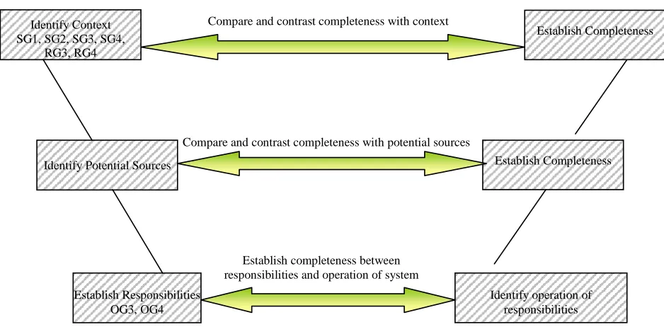
that although +PFW does address the requirements of implementing and operating a PFW system successfully it does not deal with the entire establishment needs for such an implementation by inexperienced users. In order to improve this, the process elements of the Safety Framework are required in order to assist the under-standing and development of these requirements. Figure 3 and Figure 4 demonstrate how the process is improved
by introducing appropriate elements from the Safety Framework.
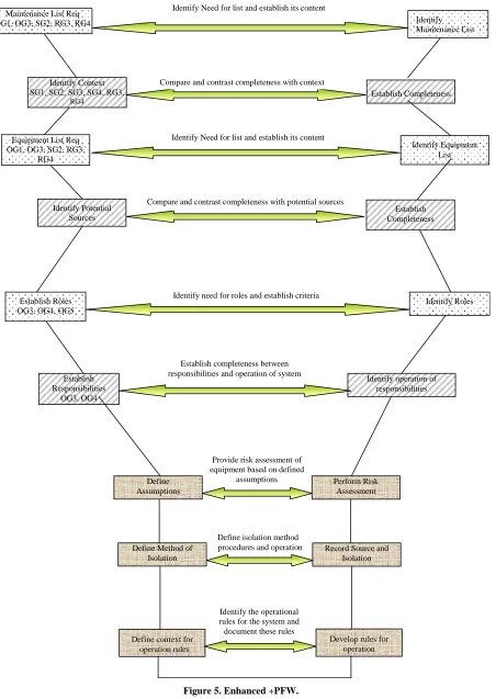
Now, these V models shown in Figure 3 and Figure 4 can be combined into a single model to represent the overall process resulting in Figure 5. This therefore shows how the process has been modified to reflect the elements required for enhancement using the appropriate elements from the Safety Framework.
Identify Need for list and establish its content
Identify Need for list and establish its content
Identify need for roles and establish criteria
Identify Maintenance List Maintenance list Req
OG1, OG3, SG2, RG3, RG4
Identify Equipment List Equipment List Req
OG1, OG3, SG2, RG3, RG4
Identify Roles Establish Roles
[image:8.595.72.524.189.434.2]OG3, OG4, OG5
Figure 3. Enhancement with component elements (1).
Compare and contrast completeness with potential sources
Establish Completeness Identify Potential Sources
Establish Completeness Compare and contrast completeness with context
Identify Context SG1, SG2, SG3, SG4,
RG3, RG4
Identify operation of responsibilities Establish Responsibilities
OG3, OG4
Establish completeness between responsibilities and operation of system
[image:8.595.63.532.469.700.2]Identify Maintenance List
Establish Completeness
Perform Risk Assessment Maintenance List Req
OG1, OG3, SG2, RG3, RG4
Define Assumptions
Identify Need for list and establish its content
Compare and contrast completeness with context
Provide risk assessment of equipment based on defined
assumptions
Identify Equipment List
Establish Completeness
Record Source and Isolation Equipment List Req
OG1, OG3, SG2, RG3, RG4
Identify Potential Sources
Define Method of Isolation
Identify Need for list and establish its content
Compare and contrast completeness with potential sources
Define isolation method procedures and operation Identify Context
SG1, SG2, SG3, SG4, RG3,
RG4
Identify Roles
Identify operation of responsibilities Establish Roles
OG3, OG4, OG5
Establish Responsibilities
OG3, OG4
Identify need for roles and establish criteria
Establish completeness between responsibilities and operation of system
Develop rules for operation Define context for
operation rules
[image:9.595.78.530.80.717.2]Identify the operational rules for the system and document these rules
D. D. BLACK ET AL. 242
6. Conclusions
The Safety Framework, as originally proposed, is capa-ble of producing an accurate model of a system even one utilising a PFW system, provided the stakeholders have a clear and unambiguous understanding of all the proc esses and procedures involved. It provides all the re-quired views to establish an appropriate representation of the required system. However, the introduction of a process enhances the Safety Framework of a PFW sys-tem if inexperienced users are involved in the establish-ment of the system requireestablish-ments. This has resulted in the enhanced form of the Safety Framework which includes +PFW in the appropriate views. Therefore, when the framework is now applied to any system the issues asso-ciated with a PFW element are clearly identified. If no PFW system is required then the +PFW method can be discounted.
Conversely, +PFW is a useful approach in the imple-mentation and operation of a PFW system. It identifies the requirements to successfully complete the process of implementing the chosen system and allows it to be op-erated effectively and safely. Where it fails is in its use, is when it is used as a standalone process. If it is not as-sociated with the Safety Framework, it is not obvious how the maintenance and equipment lists, the roles re-quired and their responsibilities, are established. These are key elements which must be included. The linkage between +PFW and the Safety Framework improves the effectiveness of the process and as a result the enhanced +PFW is more effective in providing the required output.
6. References
[1] D. D. Black, “Management of Safety–A Systems Engi-neering Approach,” Ph.D. Thesis, University of Ulster, Belfast, 2008.
[2] Health and Safety Executive, “Permit-to-Work Systems (IND(G) 98),” 3rd Edition, HSE Books, London, 1997. [3] Health and Safety Executive, “Essentials of Health and
Safety at Work,” HSE Books, London, 2006.
[4] Noble Denton Associates, “ROGS: The Railways and Other Guided Transport Systems (Safety) Regulations 2006–A Guide to ROGS,” July 2009. http://www.rail-reg. gov.uk
[5] P. G. Bishop and R. E. Bloomfield, “The SHIP Safety Case Approach,” Proceedings of International Confer-ence on Computer Safety, Reliability and Security ( SAFE-COMP ’95), Belgirate, 1995, pp 437-445.
[6] N. G. Leveson, “Safeware System Safety and Computers,” Addison-Wesley, White Plains, 2001.
[7] D. Attwood, F. Kahn and B. Veitch, “Occupational Ac-cident Models–Where have We been and Where are We Going?” Journal of Loss Prevention in the Process In-dustries, Vol. 19, No. 6, 2006, pp. 664-682.
[8] M. E. C. Hull, K. Jackson and A. J. J. Dick, “Require-ments Engineering,” 2nd Edition, Springer, Heidelberg, 2005.
[9] Health and Safety Executive, “Guidance on Permit-to- Work Systems: A Guide for the Petroleum, Chemical and Allied Industries,” HSE Books, London, 2005.
[10] International Association of Oil & Gas Producers, “Guide- lines on Permit to Work (PTW) Systems,” Report No. 6.29/189, January 1993, pp. 1-30.
[11] D. D. Black, M. E. C. Hull and K. Jackson, “+PFW–A Process for System Safety,” 2009, unpublished.
[12] UK Statute Law Database, “Health and Safety at Work (Northern Ireland) Order 1978,” No. 1039(NI9), July 1978, pp. 1-10.
[13] D. D. Black, M. E. C. Hull and K. Jackson, “Systems En- gineering and Safety–A Framework,” 2009, unpublished. [14] A. Mengolini and L. Debarberis, “Safety Culture En-hancement through Implementation of IAKA Guide-lines,” Journal of Reliability and Systems Safety, Vol. 92, No. 4, 2007, pp. 520-529.
[15] R. Crook, D. Ince and B. Nuseibeh, “On Modelling Ac-cess Policies: Relating Roles to their Organisational Context,” Proceedings of 13th IEEE International Con-ference on Requirements Engineering, 2005, pp157-166. [16] C. Lowe, “A Human Factors Perspective on Safety