Abstract—This paper develops a control strategy for converters in low voltage single phase isolated microgrids. Droop control technique for low voltage is used to control the active power as function of the voltage amplitude, and reactive power as function of frequency deviation. This control suppresses the use of physical communication between the power converters by simply local measurements, allowing its connection to the system without adjustment needs. Some concepts as microgrids and types of inverters connected as grid forming, providing and supporting inverters are introduced. It is demonstrated the droop control, and it is individualized for low-voltage systems, where it is more convenient to use active power as function of the magnitude of the voltage. A novel modified droop control equation is proposed to compensate the voltage drop at line resistance. The validity of this new approach is proven by simulations that compare both droop types and presents the effective improvement in active power-sharing and voltage regulation at common bus.
Index Terms—Distributed Generation, Droop Control, Microgrids, Voltage Regulation, Power Electronics.
I. INTRODUCTION
UE to environmental concerns and constraints in power generation by traditional sources, distributed energy sources as internal combustion engines, gas turbines, microturbines, solar photovoltaic panels, fuel cells and wind power have become part of the distribution system. However, individual applications generators, besides the solutions derived, may also cause problems in the distribution system which they are connected. The best way to associate distributed generation with loads is a subsystem called Microgrid (MG).
Among the advantages of using an MG system there are increasing local reliability, reduction of losses in the feeder, contribution with local voltage, correction of voltage sag or provide functions such as uninterrupted power supply.
The concept of MG in power grids is already widely used over the last decades [1], but it also has great potential to be
Manuscript received July 18, 2016; revised August 09, 2016. This work was supported in part by CAPES and CNPq .
L. S. Araujo is with the University of Campinas, Campinas, SP. Brazil (e-mail: savoi@ dsce.fee.unicamp.br).
D. I. Narváez is with the University of Campinas, Campinas, SP. Brazil (e-mail: dante.innar@ gmail.com).
T. G. Siqueira is with the University of Alfenas at Poços de Caldas, MG. Brazil (e-mail: [email protected]).
M. G. Villalva is with the University of Campinas, Campinas, SP. Brazil (e-mail: marcelo@ fee.unicamp.br).
explored both at techniques, regulations or economic issues. There are still various possibilities of MG structures and types of control in order to achieve commercialization.
There are several definitions of MG. There is no unanimous concept established in standard that separates a MG of a conventional grid, for example, by the grid size. In general, MG can be defined as a set of loads, generators and storage systems interconnected into a single and controlled electrical system. It can be operated in isolated mode or connected with conventional electrical grid. This concept can be extended in terms of cogeneration of electricity and thermal energy for a given area [2].
In connected mode, the voltage and frequency control of the MG is made by the conventional grid, which usually can be regarded as an infinite source of power facing the MG. In stand-alone operation mode, the MG need to generate and manage its own voltage, and in alternate current (AC) operation case, it must also control the frequency of the voltage [3].
There are many architectures for MG. The criteria to define its best configuration vary according to the need of the installation site. These criteria is considered the total power system, the physical space available for installation, the geographical location, the available energy resources, maintenance of the generation and the distribution systems, environmental factors, security and others. A number of MG types can be seen in [1][2][4-6].
The control developed in this paper is intended for an AC MG, where the generators are connected in a distributed way over the AC bus and they have local control of its variables, i.e., each generating source is responsible for controlling its amounts of generated active and reactive power as well as voltage and frequency values to ensure correct operation of the system in terms of power quality, characterizing the absence of a central controller.
An example of this MG architecture is shown in Fig. 1. It can be seen that both the loads and generating sources are connected to the grid in a distributed way, allowing the sources to be installed next to strategic loads or at the end of longer circuits, aiding to reduce feeders’ losses and reducing the voltage drop in MG. The terms PV, WT, and BB denote photovoltaic panels, wind turbine and battery bank, respectively.
Study and Development of a Modified Droop
Control Strategy for Autonomous Microgrids
Lucas S. Araújo, Dante I. Narváez, Thais G. Siqueira, Marcelo G. Villalva
Fig. 1. Example of a distributed Microgrid.
There are different denominations for the converters connected to the MG, which are separated according to the function that they should run. These converters can be forming Converter, providing Converters and Grid-supporting Converters.
The Grid-forming converter (GFC) has the role to form the MG. From a stable source it provides voltage and frequency references to other converters that will perform the synchronization to the grid. In this situation, the GFC is connected to a battery bank, but it can be connected to other generating sources, nevertheless it is chosen perennial sources to maintain stable voltage values at the output of this converter. In this way, the GFC operates as controlled voltage. The Grid-providing converter (GPC) provides energy to the MG. The GPC is always connected to a primary energy source such as a wind turbine or a PV array [3][7]. It is designed to provide energy to an already energized grid. This way it cannot operate alone in the MG, it is always required a GFC to provide the voltage and frequency references. As the GFCs, the GPCs also have their own controllers that determine the active and reactive power generated through some sort algorithm, but the GPC operates as controlled current.
Finally, the Grid-supporting converter (GSC) has the function of supporting the MG. Its support is mainly in terms of regulation of voltage’s amplitude and frequency of MG. There are several types of control for the GSC, each extolling a different function. Typically, the GSC absorbs or provides active or reactive power to perform local control of voltage’s amplitude and frequency. Its source needs to be an element with energy storage capability, e.g., a bank of batteries. The GSC can operate such as controlled voltage or as controlled current.
Considering that most renewable energy sources got intermittent feature, energy storage is an indispensable part of the MG, both to store excess energy, or to provide energy in times of scarcity, and to prevent voltage sags [8].
This paper develops the droop control for electrical microgrids in low voltage; this control allows the connection of more than one source in parallel without the necessity of exclusive lines of communication between sources.
The droop control for low voltage grids concept exists in the literature, however this paper propose a novel type of droop equation. This paper presents as contribution the validation of the new droop control functionality in a low-voltage grid. Through simulations it was possible to validate the effectiveness of the proposed control.
Section II details the droop control theory for low-voltage grids. Section III shows the development of the modified droop control. Section IV demonstrates the simulation used to validate the control and the results obtained. Finally, Section IV presents the conclusions related to the work.
II. DROOP CONTROL FOR LOW VOLTAGE MICROGRIDS
The droop control for power converters was inspired by the droop control of conventional electrical grid, used in synchronous generators. Conventional droop control basically works by decreasing the delivered active power when the grid frequency increases, or increasing the supply of active power when there is a decrease in frequency.
In isolated MG situation, the MG voltage and frequency values are determined by the GFC, this means that the grid has low inertia and a dynamic determined by static power converters.
There are converters’ control that simulate the inertia of conventional grid through algorithms and digital controls [9][10]. In the case where the synchronous generators inertia is simulated, MG has a similar conventional grid dynamics, making it more appropriate to use conventional droop controllers.
To particularize the behavior of the low voltage MG, the converter connected and the MG can be simplified as two voltage sources connected via impedance, as represented in Fig. 2. From this simplification it is possible to study the behavior of MG.
In Fig. 2, VA represents the output voltage of a GFC, VB is the MG common bus voltage and Z is the line impedance. It is considered, in this case, the GFC voltage as the reference and the power flow is agreed in the direction from the converter to the grid.
[image:2.612.46.298.48.248.2]The phase diagram representing the circuit elements is showed in Fig. 3, in which the voltage VA is the reference, the voltage VB lags VA by δ angle and the current lags VA by the angle θ.
[image:2.612.360.516.558.683.2]Fig. 3. Phase diagram of the equivalent circuit of MG.
Through analysis of the circuit of Fig. 2 it is possible to write the power flow equations. Equations (1) and (2) represent the active and reactive power of the converter, respectively.
(1)
(2)
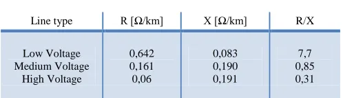
Electrical distribution networks have different line impedance characteristics according to their voltage level. Using (1) and (2), it is possible to make approaches to the behavior of networks for high or low voltage. Table I [11] shows the different line impedance values depending on the voltage level.
TABLE I – TYPICAL LINE PARAMETERS
Line type R [Ω/km] X [Ω/km] R/X
Low Voltage Medium Voltage
High Voltage
0,642 0,161 0,06
0,083 0,190 0,191
7,7 0,85 0,31
This paper considers a low voltage MG. As shown in Table I, the line impedance in low voltage grids has resistive characteristic far superior to the inductive characteristic. Thus, line’s reactance can be neglected, allowing simplification in terms of power.
For a network with R >> X, we assume that Z = R and the impedance angle θ = 0. This approximation reduces expressions of powers for the following:
(3)
(4)
It can also be considered that the lag between the grid and converter voltages is minimal [12], this means that the angle δ is small, hence cos (δ) = 1 and sin (δ) = δ (radians). This approach reduces (3) and (4) to (5) and (6):
(5)
(6)
From (5) and (6) it may be interpreted the behavior of the network and it is possible to establish the converter control.
They lead to understand that the voltage difference at the interconnection point is correlated to active power, and the variation of power angle to reactive power. This enables the implementation of control systems.
The droop control in power converters is typically implemented by following the links of the conventional grid, in which the frequency is related to active power and the voltage difference to reactive power. In this context, there are several examples in the literature of this application [13-16]. There are also cases where a generic grid is considered, and the control is independent of the characteristic of the grid line impedance [17]. The droop control has also shown effectiveness being used for grids with direct current, in which the microsource power is controlled as a function of the amplitude value of the MG's voltage [18].
In this paper, since it is a low voltage grid, it is more convenient to use droop control for low voltage, which is derived from (5) and (6). It is possible, therefore, to establish two control equations for voltage and frequency of the GFC, based on the MG characteristics.
Thereby, it can be constructed the droop control for active and reactive power of the GFC. The concept of this control is to measure the variation of the active power output and to adjust local voltage, also to measure the reactive power output and to adjust the local frequency variation. Thus, a voltage drop indicates to the other sources a need for more active power, and a fall in the frequency indicates a need of reactive power.
This is represented in (7) and (8). First, it is considered f the current MG frequency and f0 the nominal frequency, i.e., the frequency of correct operation. Similarly, V is the local voltage measured in the converter connection point, and V0 is the rated voltage of the converter. Likewise, P is the converter measured active power output and P0 is the last reference of active power, and Q is measured reactive power output and Q0 is the last reference of reactive power. Kpand kq are the slope coefficient for the active power and reactive power, respectively.
(7)
(8)
The slope coefficients are indicated by slope percentage [19]. I.e., the portion of the variation of the measured quantity to cause 100% change in controlled quantity. For example, a 3% decrease of the voltage, for a 3% kp, will cause a 100% increase in active power output.
[image:3.612.49.298.353.424.2]Fig. 4. Droop control curve for GFC at low voltage: a) voltage versus active power and b) frequency versus reactive power.
Considering the GSC with current control mode and P0 equal to zero due the source is fed to an energy storage element, the reference value for active power is determined by (9) as function of the measured values of the GSC output voltage V. Equation (10) gives the reactive power reference as function of frequency measurement.
( (9)
( (10)
III. MODIFIED DROOP CONTROL AND IMPLEMENTATION
Despite the simplicity of implementation of the droop control, a well-known drawback is the influence of the line impedance in power-sharing. For low voltage, the resistive impedance effects on active power, especially when the active power control is done by voltage amplitude variation [20].
In order to minimize the influence of the line resistance in active power sharing, we propose a novel droop equation that compensates the line resistance voltage drop by adding the value of the voltage drop to the voltage references.
Similar proposals have been adopted in [20-22], that consider virtual impedance to their control. But differently, we propose a positive feedback to the voltage references used in (7) and (9).
The voltage drop in the line resistance is proportional to the active current part of the converters current. The voltage delivered to the load by the GFC is decreased by the voltage drop in the line resistance of the GFC side as the active power provided by GFC increases. As well, the voltage measured by the GSC is decreased by the voltage drop in the line resistance of the GSC side as the active power provided by GSC increases.
This outcome influences both the active-power sharing and the variation of the load voltage amplitude nominal range. Thus, to overcome this drawback, we propose two new droop equations considering the line resistance voltage drop, (11) to GFC and (12) to GSC:
(11)
[( (12)
These new droop equations show an increased power-sharing and maintenance of load voltage between the nominal ranges.
To achieve adequate control of active power is necessary that GSC’s active current output is perfectly synchronized with the MG voltage. For reactive power control, GSC’s reactive current must be lagged by 90 degrees from MG voltage. Therefore, the use of a synchronization algorithm is necessary. In this paper it is used the Phase-Locked Loop (PLL) for synchronization, due to be the most traditionally used. At the same PLL block it is used an algorithm for RMS measurement of voltage amplitude.
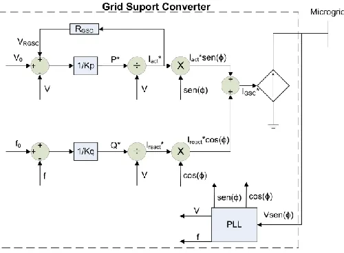
For instance of the control implementation, Fig. 5 shows the droop control block diagram used in this work to GSC. This control, derived from (10) and (12), clearly shows that the active power reference is determined by the measured values of GSC voltage. Also, the reactive power reference is determined by the measured values of GSC’s frequency. It is showed the voltage drop compensation too. The controllable current source represents the full-bridge inverter that receives the current reference. Likewise, the GFC control implementation follows (8) and (11), due GFC is featured by voltage control, for its case PLL is not necessary.
Fig. 5. Block diagram of GSC as a current source.
IV. RESULTS AND SIMULATION
To demonstrate the operation of the droop control for low voltage MG, simulations were performed emphasizing the active power control due to the variation of the MG voltage amplitude, and the reactive power control as function of MG voltage frequency.
It is proposed a simulation with two converters connected in parallel by line impedance feeding a complex load. One converter is design as GFC and the other as GSC.
[image:4.612.314.564.327.511.2]This situation represents fairly the low voltage characteristics, allowing the use of the simplifications considered previously. The equivalent circuit is showed in Fig. 6, in which the adopted positive directions of current, voltage and power variables are indicated. It is considered a constant impedance load of Zload = 4.84+j2.07Ω, which implies a power factor of 0.92.
Fig. 6. Simulation of a Microgrid circuit.
The MG components were sized based on typical values for micro generation devices. The same rated power of 5 kW to GSC and GFC was established, the nominal line voltage amplitude is Vload = 220V. The variation of voltage amplitude and frequency by GFC follows the limits allowed by Brazilian standards [23]. The nominal voltage amplitude varies by 5% above or below, and the frequency varies from 59.5Hz to 60.5Hz. The nominal frequency is 60Hz.
From these definitions it is possible to calculate the control coefficients kp and kq of active and reactive power, respectively. The equations (13) and (14) show the coefficients calculation. In this case Pmax is considered equal to the value of the rated power of the converters and Pmin the same value of Pmax but with opposite signal, the same goes to Qmax and Qmin.
(13)
(14)
Two situations were simulated for the same circuit showed at Fig. 6 to demonstrate the effectiveness of the modified droop control proposed. One situation without the modified droop control and other with it implemented.
[image:5.612.317.567.50.253.2] [image:5.612.45.303.143.255.2]The first simulation we utilized (7) and (8) to GFC control, and (9) and (10) to GSC control. The results are presented in Fig. 7. In Fig. 7 (a) is showed the total active and reactive load power, as well as GFC’s and GSC’s power amounts. In Fig. 7 (b) is showed the variation of load voltage amplitude as function of active power. And in Fig. 7 (c) the voltage frequency variation is displayed as function of reactive power.
Fig. 7. Simulation without modified droop control: (a) Load, GFC and GSC Powers; (b) Load voltage; (c) Voltage frequency.
In Fig. 7, after steady state, PGFC = 4298W and PGSC = 3257W, this indicates a difference of 1041W in power-sharing between the converters. Besides, the load voltage is stated Vload = 204V, a value below of the allowed limits (209V to 231V). The reactive power sharing is achieved by the frequency variation.
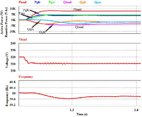
The second simulation we utilized (11) and (8) to GFC control, and (12) and (10) to GSC control. Fig. 8 presents this control simulation with the same variables of Fig. 7.
Using the modified droop control as can be seen in Fig. 8, it can be notice that the power sharing was much precise. At steady state, PGFC = 3881W and PGSC = 4222W, indicating a difference of only 341W between the converters. Also the load voltage remains at the allowed limit, Vload = 210V. The reactive power is not affected by this modification.
[image:5.612.323.567.488.689.2]V. CONCLUSIONS
The association of loads and generators in microgrid allows locally control of the sources, so it does not interfere in the conventional system. The grid's voltage amplitude control and frequency is essential to increase potential inclusion of distributed power sources in the power system. An alternative that does not require physical communication between converters for performing this control is the droop control for low-voltage MG. This feature allows the interconnection of the converters without any adjustments in the system.
This paper showed the implementation of the droop control for low-voltage. We proposed a modified droop control, adding the value of the voltage drop, due to the line resistance, to the voltage reference of droop control. Simulations of both droop control and modified droop control were presented and compared, realizing the real improvement in active-power sharing. Furthermore, the load voltage amplitude was also corrected to the allowed standard range.
REFERENCES
[1] M. Soshinskaya, W. H. J. Graus, J. M. Guerrero, and J. C. Vasquez, “Microgrids: experiences, barriers and success factors,” Renew. Sustain. Energy Rev., vol. 40, pp. 659–672, 2014.
[2] R. H. Lasseter, “MicroGrids,” 2002 IEEE Power Eng. Soc. Winter Meet. Conf. Proc. (Cat. No.02CH37309), vol. 1, pp. 305–308, 2002.
[3] Matos, J. G. Controle de Potência em Microrredes CA Isoladas com Aerogeradores e Bancos de Baterias Distri-buidos. 2014. 203f. Tese (Doutorado em Engenharia Elétrica) – Programa de Pós-Graduação em Engenharia de Eletricidade, Universidade Federal do Maranhão, São Luís, 2014.
[4] H. Jiayi, J. Chuanwen, and X. Rong, “A review on distributed energy resources and MicroGrid,” Renew. Sustain. Energy Rev., vol. 12, no. 9, pp. 2465–2476, 2008.
[5] M. Barnes, G. Ventakaramanan, J. Kondoh, R. Lasseter, H. Asano, N. Hatziargyriou, J. Oyarzabal, and T. Green, “Real-world MicroGrids - An overview,” 2007 IEEE Int. Conf. Syst. Syst. Eng. SOSE, 2007.
[6] R. Zamora and A. K. Srivastava, “Controls for microgrids with storage: Review, challenges, and research needs,” Renew. Sustain. Energy Rev., vol. 14, no. 7, pp. 2009–2018, 2010.
[7] J. Rocabert, A. Luna, F. Blaabjerg, and P. Rodríguez, “Control of power converters in AC microgrids,” IEEE Trans. Power Electron., vol. 27, no. 11, pp. 4734–4749, 2012.
[8] T. S. Ustun, C. Ozansoy, and A. Zayegh, “Recent developments in microgrids and example cases around the world - A review,” Renew. Sustain. Energy Rev., vol. 15, no. 8, pp. 4030–4041, 2011.
[9] J. Liu, Y. Miura, and T. Ise, “Dynamic Characteristics and Stability Comparisons between Virtual Synchronous Generator and Droop Control in Inverter-Based Distributed Generators,” The 2014 International Power Electronics Conference, no. 3, pp. 1536–1543, 2014.
[10] Y. Du, J. M. Guerrero, L. Chang, J. Su, and M. Mao, “Modeling, analysis, and design of a frequency-droop-based virtual synchronous generator for microgrid applications,” 2013 IEEE ECCE Asia Downunder - 5th IEEE Annu. Int. Energy Convers. Congr. Exhib. IEEE ECCE Asia 2013, pp. 643–649, 2013.
[11] A. Engler, “Applicability of droops in low voltage grids,” Int. J. Distrib. Energy Resour. Smart Grids, no. 1, pp. 1–5, 2005.
[12] H. Laaksonen, P. Saari, and R. Komulainen, “Voltage and frequency control of inverter based weak LV network microgrid,” 2005 Int. Conf. Futur. Power Syst., no. 2, 2005.
[13] A Engler, “Control of parallel operating battery inverters,” Photovolt. Hybrid Power Syst., no. 49, pp. 1–4, 2000.
[14] R. A. Mastromauro, M. Liserre, a. Dell’Aquila, J. M. Guerrero, and J. C. Vàsquez, “Droop control of a multi-functional PV inverter,” IEEE Int. Symp. Ind. Electron., pp. 2396–2400, 2008.
[15] W. Yao, M. Chen, J. Matas, J. M. Guerrero, and Z. M. Qian, “Design and analysis of the droop control method for parallel inverters considering the impact of the complex impedance on the power sharing,” IEEE Trans. Ind. Electron., vol. 58, no. 2, pp. 576–588, 2011.
[16] J. M. Guerrero, L. G. de Vicuna, J. Matas, M. Castilla, and J. Miret, “A wireless controller to enhance dynamic performance of parallel inverters in distributed generation systems,” IEEE Trans. Power Electron., vol. 19, no. 5, pp. 1205–1213, 2004.
[17] K. De Brabandere, S. Member, B. Bolsens, S. Member, J. Van Den Keybus, S. Member, A. Woyte, and J. Drie-sen, “A Voltage and Frequency Droop Control Method for Parallel Inverters,” IEEE Trans. POWER Electron., vol. 22, no. 4, pp. 1107–1115, 2007.
[18] R. A. F. Ferreira, P. G. Barbosa, and H. A. C. Braga, “Analysis of Non-Linear Adaptive Voltage Droop Control Method Applied To a Grid Connected Dc Microgrid,” pp. 1067–1074, 2013.
[19] BUSH, Stephen F. Smart grid: Communication-enabled intelligence for the electric power grid. United King-dom: John Wiley & Sons, Ltd, 2014 [20] J. M. Guerrero, J. Matas, V. Luis Garcia de, M. Castilla, and J.
Miret,"Decentralized Control for Parallel Operation of Distributed Generation Inverters Using Resistive Output Impedance," Industrial Electronics, IEEE Transactions on, vol. 54, pp. 994- 1004, 2007. [21] H. Liu, Y. Chen, S. Li and Y. Hou, "Improved droop control of isolated
microgrid with virtual impedance", 2013 IEEE Power & Energy Society General Meeting, 2013.
[22] U. Patel, D. Gondalia and H. Patel, Advances in Energy Research, vol. 3, no. 2, pp. 81-95, 2015.