© 2019, IRJET | Impact Factor value: 7.211 | ISO 9001:2008 Certified Journal
| Page 62
Smart Bus Fare Collection System
Nandini M S
1, Manisha
2, Pooja D
3, Poonam Sharma
4,Ramya M
51
Associate Professor, Department of Informational Science and Engineering, NIE Institute of Technology, Mysore
2,3,4,5
UG Scholar, Department of Informational Science and Engineering, NIE Institute of Technology, Mysore
---***---Abstract –
Smart Bus Fare Collection System implementedby RFID card. This is a user friendly system, which will automatically identify the passenger and deduct the passenger’s fare according to the distance travelled. The Radio Frequency Identification (RFID) card is used to make the identification of passenger and transaction very precise. Compared to the paper based ticketing system using of RFID cards are more convenient and reusable. RFID cards are distributes among the public. By collecting the personnel details an account will be created and unique ID will be assigned to each person with RFID cards .By accessing this database, it is thus possible to identify the traveler, check his account and deduct the fare from his/her account. Creating database facilitates efficient filtering of anti-social elements and gives firm assurance to both passenger and Public Transport System (PTS) about the transaction. The web based application is used to send push notifications and also for the RFID card renewal process
.
IOT based web-page monitor system
helps to overcomes all the problems faced in bus with.
Key Words
:
Internet Of Things (IOT), Network Security, Radio Frequency Identification(RFID).
1. INTRODUCTION
Technological advantages have played a role in hundreds of years of successes.One mode of such transportation is roadways. People travel to different places due to work every day within the cities or outside. Roadways have made the travelling comfortable for regular passengers. The transport administration provides passes for the regular passengers to travel in buses within cities, which is still a manual process. The regular passengers have to go the administration and fill the form (paper work) and the bus passes. For this process the passengers have to wait in long queues and also it. Consumes more time to issue the pass till then the user has to get the normal ticket for travelling. The more manual work which makes more complications. Now in the existing system it has many drawbacks where in the passenger has to wait in long lines to get the bus pass and also the renewal process is very tedious as again passenger has to get to the administration. People also experience situations such that proper returns (money) are not provided by the conductor after issuing the ticket. Considering the above drawbacks, technology can be mapped with the public transportation services to make passengers feel comfortable and also affordable to use the public transportation. One such idea is "E-Bus Ticket
Generation”, where the user is given an android application to register for the service. A RFID card is issued to the user which works as bus pass and user has to load some amount to it. When the user wishes to travel in the bus he/she needs to swipe the RFID card in the reader installed in the bus so that an e-ticket is issued to the user and a push notification is sent to the conductor. The user can renew the pass by using the android application. The above system emphasizes less manual work, eco-friendly and also creates a technological link within the user and administration, also it is time efficient.
1.1
LITERATURE SURVEY
In the present era road transportation is one of the easiest and fastest transportation mode to move from one place to another. In present system the user has to go to the Transport (bus) administration for the renewal of the bus pass as we all know bus pass is given to the passengers who travel daily from one place to another place for the renewal of bus pass, in which the customer have to wait in long queue and get the work done. If the passenger has not renewed the pass at correct time then the passenger have to pay and get the ticket from the conductor, which will be given in the form of paper which contradicts eco-friendly environment. The system mandates the requirement of RFID cards for all the people wanting to use the railways which has become easier with the initiatives taken by the Indian government. The process of travelling would involve a ticket checker empowered with a wireless hand-held device consisting of a card reader[1]. Cloud Computing inherits pay-on-demand resource deployment, great scalability and pervasively-accessibility from cloud computing, without lacking considerations to protect security and to preserve privacy [2]. 17 main device and information systems are consisted of Beijing metro information system. The most prominent of them is automatic fare collection system (AFC) because it directly interacts with passenger and is the exclusive way of metro revenue. So the system safety and security of AFC system is outstanding [3]. . A user-friendly app “SwipeNgo” has been developed on Android Operating System (OS) to make the whole journey of a passenger enjoyable and hassle-free. This system eliminates the usage of paper-tickets [4].
1.2 Existing System
© 2019, IRJET | Impact Factor value: 7.211 | ISO 9001:2008 Certified Journal
| Page 63
pass is issued for one month and the procedure for bus passrenewal is manual. The passengers should wait in long lines to get a monthly bus pass which is very time consuming. The limitations of existing system are manual process, time consuming, the passengers should wait in long lines.
1.3 Proposed System
The proposed system here emphasizes the automatic ticket generation and improvement of bus pass renewal procedure. We create an account for each passenger and issue a smart card with RFID. The users can go to online website and send request to load particular amount. The amount will be loaded in his card. The users can swipe the card when he gets into the bus. The distance travelled will be calculated and the amount for the journey will be deducted from his account. If the account has no enough balance a warning notification will be displayed on swiping the card.As the users get into bus and swipe their card, the conductor will get the push notifications to his mobile. As much push notifications he get, there must be same number of persons travelling. By this conductor can easily identify the persons without tickets. An option for bus location identification is provided in the project. The main advantages of the proposed system are less time consumption eco - friendly that is paper work will reduce and also cost efficient.
2. SYSTEM MODELLING AND DESIGN
This implementation is aimed at a real time usage of Smart Bus Fare Collection system and does not compromise on the security. It guarantees us that the proposed project is simple, efficient and cost effective.
A. Problem Definition
There are a number of reasons why Wi-Fi might be the real pick.
1. Wi-Fi technology is economical.
2. Users compatibleness is considered and given more preference
B. Methodology
RFID has been an emerging technology in recent years. RFID consists of two components, RFID Tag and RFID Reader. RFID Tag contains information such as name, address and mobile number. RFID reader reads the above information’s from the RFID Tag. IR sensor is used to count the number of persons entering into the bus. Internet of Things define the concept of network devices to sense and collect data from the world around us, and then share that data across the Internet where it can be processed and utilized for various interesting purposes.
C. The Internet of Things (IOT)
In IOT is the network of physical objects or "things‖ embedded with electronics, software, sensors, and network connectivity, which enables these objects to collect and
exchange data. An Internet of Things allows objects a sensed and controlled remotely across existing network infrastructure, creating opportunities for more direct integration between the physical world and the computer-based systems resulting in improved efficiency, accuracy and economic benefit. Each thing is uniquely identifiable by its embedded computing system but is able to inter-operate within the existing Internet infrastructure.
[image:2.595.356.512.247.459.2]2.1 System Models
Fig.1: Use case diagram
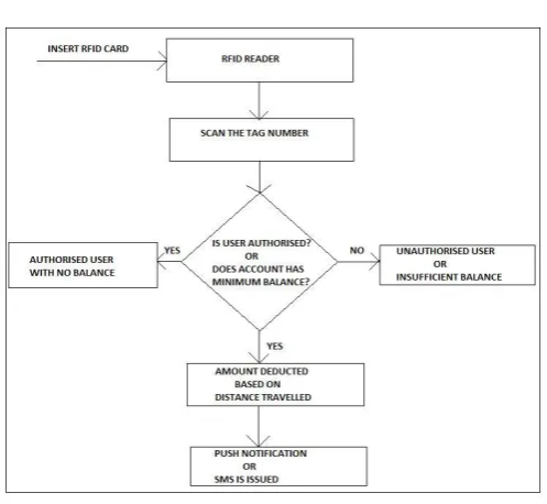
2.2 Data flow diagram
[image:2.595.308.557.514.743.2]© 2019, IRJET | Impact Factor value: 7.211 | ISO 9001:2008 Certified Journal
| Page 64
The data flow diagram is initialized by inserting the RFIDcard to RFID reader. The RFID reader scans the RFID tag number. The tag number checked, whether it belongs to authorized user or not along with account has minimum balance or not. If the user is authorized and as minimum balance the amount will be deducted from the account and also get push notification as E-ticket if is an android phone. If the mobile is not an android E-ticket as SMS. If it is not an authorized user or if there is insufficient balance then an alert notification is sent to conductor.
[image:3.595.56.276.263.489.2]2.3 Architecture Diagram
Fig 1.1: Architecture diagram
2.4 Algorithm
We are using three algorithms • Haversine algorithm • FCM algorithm
• Reverse Geocoding algorithm
2.4.1 Haversine algorithm
The calculation of the distance between two points on the surface of the Earth proceeds in two stages: (1) to compute the “straight-line” Euclidean distance these two points (obtained by burrowing through the Earth), and (2) to convert this distance to one measured along the surface of the Earth.
i) The origin is at the Earth’s centre;
ii) The x-axis passes through the Prime Meridian (0 longitudes);
(iii) The xy-plane contains the Earth’s equator (and so the
positive z-axis will pass through the North Pole)
Note that the angle θ is the measurement of latitude, and the angle φ is the measurement of longitude, where 0 ≤ φ < 360, and −90 ≤ θ ≤ 90. Negative values of θ correspond to points in the Southern Hemisphere, and positive values of θ correspond to points in the Northern Hemisphere. When w e use spherical coordinates which is typical for the radial distance R to vary; however, here we may fix it to be the average radius of the Earth:
R ≈ 6, 378 km
Thus, we assume that we are given two points P and P determined by their respective latitude-longitude pairs: P (θ, φ) , P (θ, φ) . In Cartesian coordinates we have P = P (x, y, z) and P = P (x, y, z) , where x, y, and z are determined by the spherical coordinates through the familiar equations:
x = R cos θ cos φ y = R cos θ sin φ z = R sin θ
The Euclidean distance d between P and P is given by the three-dimensional
Pythagorean Theorem:
d = (x − x) + (y − y) + (z − z) .
The much of our work will be in computing the distance in terms of the spherical coordinates. Converting the Cartesian coordinates to spherical coordinates, we get d /R = (cos θ cos φ − cos θ cos φ )+(cos θ sin φ − cos θ sin φ )+(sin θ − sin θ )
2.4.2 FCM (Fire Cloud Messaging) algorithm
Firebase Cloud Messaging (FCM) is a cross-platform messaging solution that lets you reliably deliver messages at no cost. Using FCM, notification are sent to a client app regarding new email, messages or other data is available to sync. Notification messages are send, to drive user retention and re-engagement. For use cases like instant messaging, a message having payload of up to 4KB can be send to a client app.
An FCM implementation includes two main components for sending and receiving:
1. A trusted environment such as Cloud Functions for Firebase or an app server on which to build, target, and 2. Send messages.
© 2019, IRJET | Impact Factor value: 7.211 | ISO 9001:2008 Certified Journal
| Page 65
Messages can be sent via the Admin SDK or the HTTP andXMPP APIs. For sending marketing or for testing or engagement messages with powerful built-in targeting and analytics, along with these one can also use the Notifications composer.
2.4.3 Reverse Geocoding algorithm
Reverse geocoding is the process of back (reverse) coding of a point location (latitude, longitude) to a readable address or place name. By Combining geocoding and routing services, reverse geocoding is a critical component of mobile location-based services and Enhanced 911 to convert a coordinate obtained by GPS to a readable street address which is easier to understand by the end user. This permits the identification of nearby street addresses, places, and/or areal subdivisions such as neighborhoods, county, state, or country .Reverse geocoding can be carried out by services which process a coordinate which are similar to the geocoding process. For example, when a GPS coordinate is entered the street address is interpolated from a range assigned to the road segment in a reference dataset that the point is nearest to. If the user provides a coordinate near the midpoint of a segment that starts with address 1 and ends with 200, the returned street address will be somewhere near 100. This approach to reverse geocoding does not return actual address, but based on the predetermined range it only returns estimates of what should be there. Alternatively, coordinates for reverse geocoding can also be selected on an interactive map, or extracted from static maps by geo referencing them in a GIS with predefined spatial layers to determine the coordinates of a displayed point.
3. Hardware Collection and Assembly
RFID Technology
GCM Technology
Cloud storage
GSM Modem
3.1 RFID Technology
RFID Structure is continuously composed of 2 main hardware components. The transponder which is located on the product to be scanned and the reader which can be either just a reader or a read & write device, depending upon the system design, technology employed and the requirement. The RFID reader characteristically comprise of a radio frequency module, a controlling unit for configurations, a monitor and an antenna to investigate the RFID tags.RFID Tag – The actual data carrying tool of an RFID structure, in general comprise of an antenna (coupling element) and an electronic micro-chip.
3.2 GCM Technology
GCM is advanced push technology developed by Google for Android platform. It replaces Android’s old push technology C2DM (Cloud to Device Messaging) which has many limitations.
3.3 Cloud storage
Cloud storage is defined as "the storage of data online in the cloud" wherein a company's data is stored in and accessible from multiple distributed and connected resources that comprise a cloud. There are many benefits to using cloud storage does have the potential for security and compliance concerns that are not associated with traditional storage systems. Cloud storage can provide the benefits of greater accessibility and reliability; strong protection for data backup, archival and disaster recovery purposes; overall storage costs as a result of not having to purchase, manage and maintain expensive hardware.
3.4 GSM Modem
A GSM modem is a wireless modem that works with a GSM wireless network. A wireless modem is similar to dial-up modem. The main difference between them is that a wireless modem sends and receives data through radio waves while a wireless modem sends and receives data through radio waves. Like a GSM mobile phone, a GSM modem requires a SIM card in order to operate.
4. CONCLUSION
The fare collection problem has been eliminated Moreover, the project phase is completed successfully by using smart card .This project is made with pre-planning, that it provides flexibility in operation. This innovation has made more desirable and economical. This project “SMART BUS FARE COLLECTION SYSTEM” is designed with the hope that it is very much economical and helpful for passengers and as well as conductors during Journey
REFERENCES
[1] Ticketing Solutions for Indian Railways using RFID Technology by Venugopal, PrasanthHari Prasad , IV B.tech EEE Amrita VishwaVidyapeetham, Coimbatore TamilNadu-641105, 2009 International Conference on
Advances in Computing, Control, and
Telecommunication Technologies
© 2019, IRJET | Impact Factor value: 7.211 | ISO 9001:2008 Certified Journal
| Page 66
[3] Metro Automatic Fare Collection System Safety and Security By Zhongliang.Liu, Shifeng.Li, Tiedong.Chen3