Stress-Oriented Structural Optimization for Frame Structures
Shuangming Chaia, Baiyu Chena, Mengyu Jia, Zhouwang Yanga, Manfred Laub, Xiao-Ming Fua, Ligang Liua,∗
aSchool of Mathematical Sciences, University of Science and Technology of China, Hefei, China 230026 bSchool of Computing and Communications, Lancaster University, Lancaster, UK LA1 4WA
Abstract
To fabricate a virtual shape into the real world, the physical strength of the shape is an important consideration. We introduce a framework to consider both the strength and complexity of 3D frame structures. The key to the framework is a stress-oriented analysis and a semi-continuous condition in the shape representation that can both strengthen and simplify a structure at the same time. We formulate a novel semi-continuous optimization and present an elegant method to solve this optimization. We also extend our framework to general solid shapes by considering them as skeletal structures with non-uniform beams. We demonstrate our approach with applications such as topology simplification and structural strengthening.
Keywords: 3D printing, fabrication, stress analysis, optimization, topology simplification
1. Introduction
We have witnessed many developments in the area of com-putational fabrication in recent years [1, 2, 3, 4]. As 3D printers become increasingly common and affordable, there is a great need for tools that consider the physical properties of virtual ob-jects. When bringing virtual objects into the real world through 3D printing, the strength of an object is one such important con-sideration. We present a framework to analyze both the strength and complexity of 3D frame structures, where a structure con-sists of a set of beams. The motivations for focusing on frame structures are that these structures are common in architectural models, they can also represent general 3D shapes, and they can be 3D printed as a real-world frame structure to represent the virtual shape without an excessive amount of printing ma-terial.
There has been some recent work exploring the idea of struc-tural analysis of 3D printed shapes [5, 6, 7]. There also exists work that analyze structural parts and reduce the cost of 3D printing by building a skin-frame structure [8] or a honeycomb-cells structure [9]. However, previous methods optimize the structure problem iteratively between two parts: a geometry op-timization and a topology opop-timization. In this paper, we intro-duce a single stress-oriented framework to analyze the strength and topology complexity of 3D frame structures simultaneously. A key contribution different from previous work is that we have a problem formulation and a semi-continuous condition in our shape representation. This condition can remove structurally redundant elements to reduce the overall shape complexity with-out sacrificing its structural strength.
∗Corresponding author
Email addresses:[email protected](Shuangming Chai),
[email protected](Baiyu Chen),
[email protected](Mengyu Ji),[email protected]
(Zhouwang Yang),[email protected](Manfred Lau),
[email protected](Xiao-Ming Fu),[email protected](Ligang Liu)
We formulate our problem to optimize scalar parameters of a frame structure such that it is 3D printable with high strength, while taking into account the volume, semi-continuous, sym-metric, and sparsity constraints. These constraints are quite in-tuitive, as they limit the size and complexity of the output struc-ture while maintaining its aesthetics. The idea is to strengthen weak parts while maintaining the overall volume of the shape, and optionally changing the topology and keeping the shape symmetry. In particular, the semi-continuous constraint is key to our formulation, as it includes a choice between lower and upper bounds and a value of zero for each parameter in the shape representation. An element within a shape with a pa-rameter value of zero will disappear. Our formulation of this condition allows us to explore the tradeoffs between strength and complexity in frame structures. The user can also control the tradeoffto choose among structures with various simplified topologies and high strength.
We use stress as a measure of strength of an object. We consider the frame structure as a set of beam elements and com-pute the stress of each element. Our stress-oriented structural optimization then minimizes the maximal stress of all elements. The semi-continuous condition in our shape representation re-quires a non-trivial solution to this problem. Hence we formu-late a novel semi-continuous optimization and present an el-egant method, the alternation direction method of multipliers (ADMM) algorithm, to solve it. Based on our framework on frame structures, we extend it to general tetrahedral meshes. By considering a tetrahedral mesh as a skeletal structure, the formulation and optimization method can be easily applied to a skeletal structure.
The contributions of our work are: (i) a stress-oriented frame-work to analyze both the strength and structural complexity of 3D frame structures with a semi-continuous condition; (ii) a semi-continuous optimization to minimize the maximal stress of a structure and an elegant method to solve this optimization; (iii) an extension to tetrahedral meshes by constructing skeletal structures and considering as frame structures; and (iv) applica-tions of our framework to structural strengthening and topology simplification. Section 3 describes the stress analysis frame-work and the representation of an input shape as a frame struc-ture. Section 4 describes our problem formulation including the objective function, the semi-continuous condition, and var-ious constraints in our stress-oriented optimization. Section 5 describes a reformulation of the original problem formulation into a semi-continuous optimization such that it can be solved with the ADMM algorithm. Section 6 describes the extension of our framework to tetrahedral meshes.
2. Related Work
Structural Analysis for Fabrication. With the rapid develop-ment of techniques for 3D printing, many researchers have re-cently studied geometric processing problems for the purpose of fabrication. These fabrication-aware methods are typically led by a stress analysis that uses the finite element method. Stava et al. [5] introduce a method that analyzes the stress of a model and deforms it by hollowing, thickening and strut in-sertion. Zhou et al. [6] present a method to search for the worst-case stress under forces from all possible directions. Langlois et al. [10] use a stochastic finite element method to compute failure probabilities which can analyze the static soundness of one object. Zhou et al. [11] present a direct shape optimiza-tion method which penalizes geometric deviaoptimiza-tion while bound-ing the stress under specific external loads. Chen et al. [12] propose a finite element discretization scheme to use a reduced basis for fast stress analysis. Chen et al. [13] analyze elastic deformation caused by gravity to solve the inverse problem of computing a shape that when fabricated deforms naturally to a target shape. Pr´evost et al. [3] explore the problem of deform-ing shapes to make them physically balance. Among this area of work, we contribute a stress-oriented problem formulation for automatically strengthening a frame structure while simpli-fying its structural complexity.
Structural Simplification for Fabrication. There has been work on problems which aim to simplify the complexity of the struc-ture of 3D shapes for fabrication. Many methods are based on decomposing a 3D shape into smaller pieces and then assem-bling them to form the original shape or a resemblance of it. Luo et al. [14] suggest a method to 3D print large objects by first segmenting an object into smaller parts and then assem-bling the parts to form the larger shape. Hildebrand et al. [15] create parts from a 3D shape that can then be fabricated and assembled in an optimal direction. Interlocked planar [16, 17] or solid pieces [18, 19, 20] can be used to form a shape that re-sembles the original. Zimmer et al. [21] approximate surfaces by building physical structures with the Zometool construction
system. Vanek et al. [22] present a method to divide a mesh into parts which are then efficiently packed into space for 3D printing. Instead of decomposing a shape into smaller pieces, we simplify a frame structure by possibly removing elements from it. We contribute a semi-continuous optimization for this purpose.
Special Structure Design. Motivated by existing architectural structures, some types of special 3D printed structures have been explored. Some structures, like skin-frame structure [8] or honeycomb-cells structure [9], are designed to reduce the cost of 3D printing via stress analysis. These methods are used for constructing the interior supporting structure of a solid object and these structures are cost-effective and are stable with high strength. Some structures are designed as the support structure necessary for 3D printing. The reduction of support structure can save printing time and material [23, 4]. A bridge struc-ture [4] can reduce the cost and meet stability conditions. Yang et al. [24] design a support-free structure to fabricate a balanced object without interior supports. Recently inspired by some ma-terials in the nature, microstructures [25, 26, 27, 28] become popular, which are composed of tileable and printable small scale assemblies made of one or several materials. A framework is proposed [29] to generate statically sound and materially ef-ficient frame structures with different types of cross sections. In this paper, we focus on strengthening and simplifying frame structures consisting of beams. We can also extend our frame-work to converting general meshes to skeletal representations for our analysis.
3. Preliminaries
This section describes the stress analysis and the representa-tion of an input 3D shape of our algorithm as a frame structure. The stress computation described here is used in our optimiza-tion in Secoptimiza-tion 4.
3.1. Stress Computation
In continuum mechanics, stress is a physical quantity that expresses the internal forces that neighboring particles of a con-tinuous material exert on each other [30, 31]. The strength of a material is measured in force per unit area, which depends on its capacity to withstand axial stress, shear stress, bending, and torsion. A static elastic object satisfies the following equilib-rium equation:
−divσ(u)=f, inΩ,
u=0, onΓH,
σ(u)·n=g, onΓN,
(1)
whereuis the displacement,σis the stress tensor,fis the body force, andg is the surface force. This differential equation is defined in the region of an objectΩ,ΓH andΓN are two open subsets of the boundary of Ω, such that∂Ω = ΓH ∪ΓN and ΓH∩ΓN =∅. We take the discretized form of this system, i.e. the linear equilibrium equation:
Node
[image:3.595.79.237.83.184.2]Beam
Figure 1: A frame structure consists of nodes and beams. The positions of nodes and the cross sections of beams defines the shape of a frame structure. For the sake of simplicity, we set each beam to be a cylindrical shape, which use a single radius to control the strength of a beam. The elastic properties of a frame structure are determined by its shape and the material of each beam.
whereK is the stiffness matrix andF is the external loads in-cluding body forces and surface forces. Note that the displace-mentuis in the finite element space of piecewise linear contin-uous functions, which is different from the space in the contin-uous case (Equation 1).
3.2. Frame Structure
As shown in Figure 1, a frame structure consists of a set of beams and nodes where the beams are connected to each other at the nodes. In our framework, each beam is regarded as a simple cylindrical shape with a radius and a length. The beams defines the topology (i.e. the connectivity between nodes) of the frame structure. According to theory on frame structures [32, 33], the stiffness matrixKin Equation (2) can be computed for a frame structure, whereKdepends on the node positions and beam radii [8]. The forces in this equation are gravity or exter-nal loads we specify. We can then solve for the displacement and compute the stress for each beam in the frame structure. Al-though the stress varies in different parts of the beam, we only consider the largest stress for each beam.
4. Problem and Formulation
We describe our problem formally in this section, including the objective function in our optimization, various constraints, and the problem formulation. The stress analysis from Sec-tion 3 allows us to compute the stress in our optimizaSec-tion. The solution to the optimization is presented in Section 5.
4.1. Problem
Our problem involves two components: stress strengthening and topology simplification.
Stress strengthening. Structural optimization aims to determine the best design according to some physical objectives (e.g. great-est strength, maximum rigidity) under some constraints. A struc-ture fails the strength criterion when the stress (force divided by area of material) induced by the load is greater than the capac-ity of the structural material to resist the load without breaking, or when the strain (percentage extension) is so great that the element no longer fulfills its function. As acknowledged in the
literature [34, 35, 36], it is natural to use stress or strain as crite-ria for the weakness measure of a target structure. Hence we use stress as a criterion for the purpose of structural strengthening.
Structural complexity. There exists many beams in our frame structures and some of these beams are not significant to the stress of the overall structure. We may therefore remove some of them without affecting the stress of the overall shape and to simplify its structural complexity.
Problem. The input to our problem is a frame structure of beams (shown as Figure 1). Considering the above two components, our problem is to perform simultaneous stress strengthening and structural complexity reduction of the input shape under some external loads. The output is a modified frame structure with a smaller number of beams while the stress of the shape is maintained or strengthened. The radii of some beams are ad-justed while some beams are removed. The resulting shape may be 3D printed as a structure with high strength and simplified complexity.
4.2. Objective Function
Objective function. LetM be a mesh representing the frame structure. We adopt stress as a criterion for the weakeness measure of an object and minimize the maximal stress of the beams in the structure. The stress-oriented structural optimiza-tion problem can thus be formulated as:
s∗=arg min
s∈Θ
max
p∈M(s)σ(p), (3)
wheres is the vector of structural design variables, Θis the collection of all feasible design variables, and σis the stress function. The solution of the above problem iss∗, andM(s∗) is
then the output shape.
Design variables. The degree of freedom of the structural de-sign space is large in general. Hence we simplify the problem by focusing on a piecewise scaling transformation for each el-ement of the shape. LetK = (VK,EK) be the frame
struc-ture of a shape, whereVK andEK represent the set of nodes
and beams respectively. For every beam, we define a scalar si,i∈ {1,· · · ,|EK|}which is the scaling factor of the radius of
each beam (See Figure 2). Lets=(s1,s2,· · ·,s|EK|) be our set
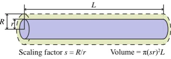
of structural design variables. We can perform many changes to the shape by adjusting these scalar variables. For example, we can adjustsito strengthen weak parts. We can re-distribute volume in the overall shape by adjustingsifor multiple parts. If
R r
Scaling factor s = R/r L
Volume = π(sr)2L
[image:3.595.346.520.660.720.2]we setso =1=(1,1,· · ·,1), thenM(so) is the original object. If we set somesi=0 then the corresponding part will disappear and we can perform topological changes to the overall shape.
4.3. Constraints
We consider various constraints in our framework to main-tain the size, aesthetics, and complexity of the output shape.
Volume constraint. We compute the shape’s volume by adding the volume of all beams. Each beam’s volume is estimated as the cross sectional area multiplied by its length. We can write the volume constraint as:
Vol(s)≤γVol(1), (4)
whereγis a user-specified value which means that the resulting volume is no more thanγof the original volume.
Symmetry constraint. In many practical applications, it is im-portant to maintain the symmetry of a shape during its struc-tural optimization, so as to maintain its overall aesthetics. Our approach can achieve this by adding symmetry constraints as follows:
si−sj=0,(i,j)∈ S, (5)
whereSis the set of index pairs of beams that we wish to main-tain symmetry with.
Semi-continuous constraint. In order to satisfy the printability of the object, the scalarsishould be within an interval [ai,bi]. For example, the scalar should be set such that the thickness of the shape is not less than the minimum manufacturable size of the 3D printer. Each scalarsican also take a zero value. Hence this leads to a semi-continuous condition:
si∈[ai,bi]∪ {0}, i∈ I={1,2,· · ·,|EK|}. (6)
Sparsity constraint. Moreover, we can add a cardinality con-straint to control the overall complexity of the structure:
ksk0≤τ. (7)
4.4. Formulation
We can now formulate our stress-oriented structural opti-mization as follows:
arg min
s
max e∈E σe(s)
s.t. Vol(s)≤γVol(1),
si−sj=0, (i,j)∈ S,
si∈[ai,bi]∪ {0}, i∈ I,
ksk0≤τ,
(8)
whereEis the set of beams in the frame structure, andσeis the stress function described in the previous section.
5. Semi-Continuous Optimization
In this section, we present the method to solve the mization described in Section 4. In the formulation of our opti-mization (Equation (8)), the scaling factorssare a set of semi-continuous decision variables [37, 38]. Theoretically, it is in general NP-hard to solve this kind of highly nonlinear optimiza-tion problem which has combinatorial nature (semi-continuous sparsity) [39, 40]. Thus we reformulate our problem and then mathematically derive an algorithm based on the ADMM (al-ternating direction method of multipliers) strategy [41, 42] to solve it. The ADMM method is designed to solve convex op-timization problems by breaking them into smaller pieces, and it has been applied to a number of problems arising in statistics and machine learning [43, 44]. The semi-continuous condition in our problem formulation leads to two sets of variables. The idea of ADMM is to split the optimization into sub-problems that iteratively find solutions to the two sets of variables.
5.1. Problem Reformulation
We add a new variableδto represent the maximum stress and introduce a variable splitting strategy (and a new variable
y) to reformulate the problem in Equation (8) as:
arg min
(s,δ,y)
δ
s.t. σe(s)−δ≤0, e∈ E,
Vol(s)≤γVol(1),
si−sj=0, (i,j)∈ S,
s−y=0,
y∈ Y,
(9)
whereY={y|aizi ≤yi ≤bizi,zi∈ {0,1},i∈ I;1Tz≤τ}. The optimals∗ is our solution. The advantage of introducing the
variableyis that it allows the decoupling of the continuous con-straint and the semi-continuous sparsity concon-straint, since each of them now applies to one specific optimization variablesory. Although we introduce an additional constraint, it is now eas-ier to solve the reformulated problem (Equation (9)) than the original one (Equation (8)).
5.2. Solution
Our solution is based on ADMM which is itself based on an augmented Lagrangian function and two sub-problems within the overall optimization. We describe these in detail in this sub-section.
Augmented Lagrangian. One typical way for solving such an optimization problem is to use an augmented Lagrangian ap-proach [45]. We use this method and define the problem’s aug-mented Lagrangian function as follows:
Lρ(s, δ,y,λ)=δ+λT(s−y)+ρ 2ks−yk
2 (10)
Algorithm 1The ADMM algorithm for structural optimization
Input:an initial structureM(so)
Step 0:Setk=0 and initializey0,λ0. Set the penalty parameter
ρand the step-sizeα;
Repeat
Step 1:Solve the (s, δ)-subproblem
(sk+1, δk+1)=arg min
(s,δ)∈D
Lρ(s, δ,yk,λk);
Step 2:Solve they-subproblem
yk+1=arg min
y∈Y
Lρ(sk+1, δk+1,y,λk);
Step 3:Update the Lagrangian multipliers
λk+1=λk+αρ(sk+1−yk+1);
Untilstopping criterion is met.
Output: an optimized frame structureM(s∗) with its optimal
variables∗.
Pseudocode. Instead of a joint optimization on the two vari-ables, the idea of ADMM is to optimize alternatively over (s, δ) andy. Algorithm 1 gives the pseudocode of our solution with ADMM. The stopping criterion in the optimization is: the value of the function has almost no change or the number of iteration steps reaches a given upper bound.
(s, δ)-subproblem. The (s, δ)-subproblem in ADMM involves a quadratic objective and the continuous constraint. We use the interior-point method to solve the subproblem:
min
(s,δ)∈Dδ+
ρ 2ks−(y
k−λk/ρ)k2, (11)
whereD={(s, δ)|σe(s)−δ≤0,e∈ E; Vol(s)≤γVol(1);si− sj=0,(i,j)∈ S}is the feasible set of continuous variables.
y-subproblem. We rewrite they-subproblem as a closed-form solution, starting with:
min
y∈Y
ky−(sk+1+λk/ρ)k2=X i
(yi−ti)2 (12)
withti=ski+1+λki/ρ. Ifyi,0, we denote
ζi=min
y∈Y(yi
−ti)2=
(ai−ti)2, ti<ai, 0, ai≤ti≤bi, (bi−ti)2, ti>bi.
Then this subproblem can be further simplified as:
min
z
X
i
ti2(1−zi)+ζizi= X
i
ti2−X i
(t2i −ζi)zi
s.t. zi∈ {0,1},i∈ I; 1Tz≤τ.
(13)
Let{t2
`1−ζ`1,t
2
`2−ζ`2,· · ·,t
2
`τ−ζ`τ}be the firstτpositive numbers
of sequence{t2
i −ζi}i∈I in descending order. The problem in
Joint part
[image:5.595.333.530.78.225.2]Bone part
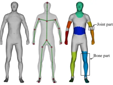
Figure 3: Converting a tetrahedral structure into a skeletal representation. Left: The input mesh; Middle: The skeleton of the mesh; Right: The mesh is decom-posed into a set of bone parts (in colors) and joint parts (in gray).
Equation (13) has the solutionz`1 =z`2 =· · · =z`τ =1; zi = 0,i<{`1, `2,· · ·, `τ}. Finally, we get a closed-form solution
yi=max(ai,min(ti,bi))·zi, ∀i∈ I
for they-subproblem (Equation (12)).
6. Extensions
We also extend our framework to skeletal shapes, which need to be converted into a tetrahedral structure for the finite element analysis. However, the number of tetrahedral elements in the overall structure may be large which can potentially lead to a large stiffness matrix and slow computation. Hence we sim-plify the computation by converting it into a skeletal represen-tation (Figure 3), which can be considered as a frame structure of non-uniform beams.
Our skeletal representation and computation of stiffness ma-trices are similar to that of [7]. We first extract a skeleton from the input mesh. The mesh is then decomposed into a set of domains according to the bones of the skeleton, where each do-main consists of its own set of vertices and tetrahedrons. Each tetrahedron belongs to only one domain. Some vertices may exist in multiple domains and these are duplicated. As shown in Figure 3, each domain is classified as either bone part (in colors) or joint part (in gray), where most parts of the mesh are bone parts. A bone part is associated with only one bone and
d D
Scaling factor s = D/d A bone of skeleton
Original mesh
[image:5.595.334.526.629.718.2]Deformed mesh
(a) (b) (c) (d)
Figure 5: The results of a frame structure of a duck. The figures are colored according to the stress for each beam with red meaning large stress and blue meaning small stress. (a) The input duck model with 1107 beams. Three external loads (marked as red arrows) are applied on the model. (b, c, d) The simplified duck models (with 1007, 957, 907 beams respectively) obtained with our approach. The resulting models are increasingly simplified while their structures still remain strong.
(a) (b) (c) (d) (e) (f)
Figure 6: Results of the eiffel tower model. (a) The input frame model with 1521 beams. (b) The computed stress (colored with red being large and blue being small) of the input model under an external load of 2N (shown by red arrow). (c) A photo of the SLS 3D printed model of the input. A small red pin is placed under the object as a size reference. (d) The simplified frame model with 1341 beams obtained by our approach. (e) The computed stress of the output model under the same external load as that of the input in (b). The output model has higher strength and reduced complexity. (f) The photo of the SLS 3D printed model of our output.
we can compute the stiffness matrix from the associated ver-tices and tetrahedra. A joint part is associated with multiple bones and the vertex coordinates associated with each bone are blended.
After the extrusion of the skeletal structure, we apply our framework to general meshes. The design variables are scaling factors, so the scaling factor is defined for every bone of the skeleton (See Figure 4). Then, the formulation and optimization are similar, except for the computation of stress, i.e. the use of von Mises stress.
A skeletal mesh shape is represented as a tetrahedral struc-ture which consists of a set of vertices and a set of tetrahedral
el-ements. For each tetrahedral element, we compute the element stiffness matrix and then assemble them into the total stiffness matrixKin Equation (2) as in [5, 6]. To compute the strength of each element, we use the von Mises yield criterion and compute the von Mises stress.
7. Experimental Results
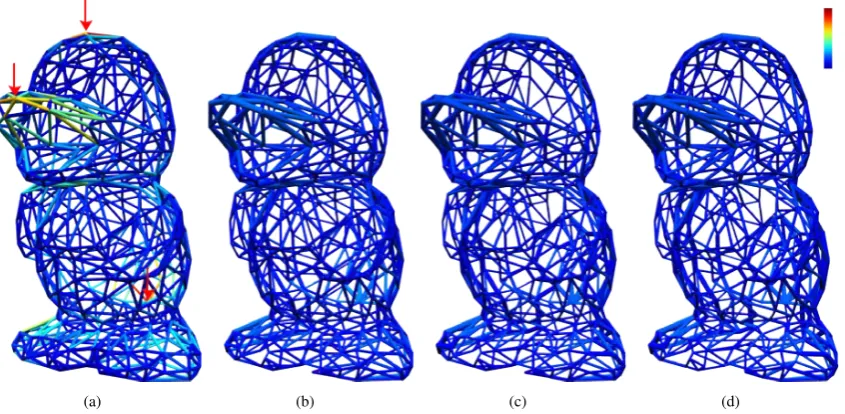
[image:6.595.65.536.346.539.2](a) (b) (c) (d)
Figure 7: Results of the hardstruct model. (a) The input model where external loads are denoted as red arrows. The hardstruct model has 1728 beams. (b) We 3D printed the input model with a Sinterstation SLS 3D printer. A small red pin is placed under the object as a size reference. (c) The resulting model obtained by our approach is structurally simplified and strengthened with our approach. The hardstruct model has 1548 beams. (d) We physically demonstrate our results by 3D printing the output model.
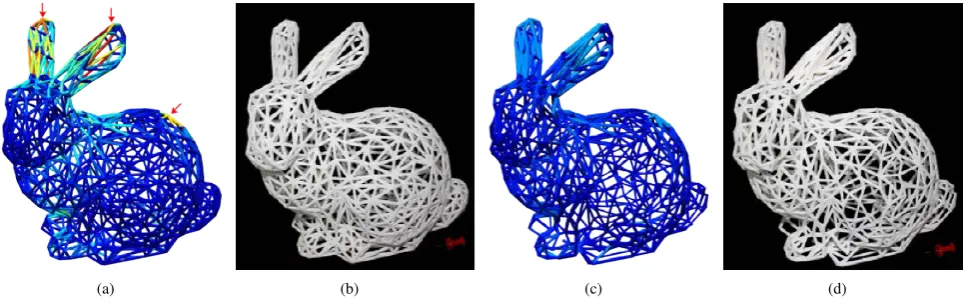
(a) (b) (c) (d)
Figure 8: Our approach analyzes an input 3D frame structure to perform simultaneous structural strengthening and simplification for 3D printing. (a) The input bunny frame model with 1569 beams. The external loads are denoted as red arrows. (b) A photo of the SLS 3D printed models of the input. A small red drawing pin is placed under the object as a size reference. (c) The resulting model obtained by our approach. The number of beams is reduced to 1319. (d) A photo of the SLS 3D printed models of our output.
Parameters. There are several parameters in our formulation. The user can change the value of the weight γto control the volume of the resulting object. We setγ=1 in our implemen-tation which means that we do not want to increase the volume of the result adjusting the shape. Another parameter isτwhich measures the complexity of the structure by measuring the num-ber of beams. Thusτcan be adjusted by the user and set to a number less than the total number of beams in the input model. We specify the external loads manually at various points of the input shapes. In the optimization, we set the penalty parameter ρto be 10 and the step-sizeαto be 0.6.
Figure 5 shows the results of our algorithm on a frame struc-ture of a duck model. We set different values of the sparsity parameter τ and obtain a sequence of results. The resulting structural shapes in Figure 5(b,c,d) are progressively simplified in the number of beams while their strengths are maintained.
Frame structures. We have tested our algorithm on various mod-els of frame structures. Figure 6 shows an example of Eiffel tower. We give an external load as input and optimize the max-imal stress. From the color in the figure, we can see that the
maximal stress is lower than it before the optimization. Since the feet of the tower are fixed, the beams connecting fixed nodes have zero stress, thereby being removed. Figure 7 and Figure 8 show the results of a complicated ‘hardstruct’ structure and a bunny. For the ‘hardstruct’ model, we set the external forces to be evenly distributed downward forces on its top nodes. For the bunny model, we set three exteranl forces on three specified positions. These frame structures are structurally strengthened and topologically simplified while their total volumes are pre-served.
Figure 9 shows two more examples whose external loads are vertical down. For the boomerang, since the given external force is vertical down, some horizontal beams have less contri-bution to the soundness, thus being removed by our optimiza-tion. The airport model has a constant gravity on each node. Note that there are also some horizontal beams removed due to the reason mentioned before.
[image:7.595.60.545.296.448.2]Figure 9: Results of applying our approach on the boomerang model (left) and the airport model (right). An external load (shown in red arrow) is applied on the boomerang model. Gravity is applied as external load to the airport model. The original models (top) have 312 and 5045 beams respectively. Our results (bottom) have 284 and 4585 beams respectively and they are both structurally simplified and strengthened compared to the originals.
method, the stress of the models can be automatically enhanced by thickening the weak parts of the models. We fabricated some of these models with FDM printers (see Figure 10).
8. Conclusion
We present a novel approach for performing structural anal-ysis on 3D shapes with simultaneous structural strengthening and simplification. The optimized shape can be 3D printed with high strength and reduced complexity. We use stress as a criterion for measuring strength and minimize the maximal stress of the shape to formulate an optimization with a semi-continuous condition. We then derive an algorithm based on the ADMM method to solve the optimization and show its ap-plicability and feasibility towards topology simplification and structural strengthening. Although this paper focuses on frame structures, our framework can be extended to general meshes by considering them as skeletal tetrahedral structures.
Our approach has some limitations. One limitation of our work is that we do not move the positions of the nodes in a structure. This means that although the structure can be much simplified, the inherent topology of the original structure re-mains the same. Moving the positions of the nodes can poten-tially be done in our optimization framework. However, this will enlarge the dimensions of the variable space and will need higher computational cost. We leave this as a future research direction.
(a) (b) (c)
Figure 10: Examples of applying our approach on skeletal shapes (top: ba-nanaman; bottom: fishing frog). (a) The original meshes; (b) Our results; (c) Photos of the FDM printed objects of our results. Note that the color shows the stress distribution
Another limitation is that the symmetry constraints may be difficult and/or tedious for humans to specify. In addition, as humans are able to easily identify any lack of symmetry, some of our simplified models may not be visually appealing as the topology may be simplified into non-intuitive patterns. We may consider this as an aesthetic constraint in the optimization in future work.
Another area of future work that is relevant for fabrication is the computation of supporting structures for FDM 3D printing. There has already been previous work in this area recently. Ap-plying our stress-oriented structural optimization to this prob-lem would be an interesting direction.
References
[1] B. Bickel, M. B¨acher, M. A. Otaduy, H. R. Lee, H. Pfister, M. Gross, W. Matusik, Design and fabrication of materials with desired deformation behavior, ACM Transactions on Graphics (TOG) 29 (4) (2010) 63. [2] S. Coros, B. Thomaszewski, G. Noris, S. Sueda, M. Forberg, R. W.
Sum-ner, W. Matusik, B. Bickel, Computational design of mechanical charac-ters, ACM Transactions on Graphics (TOG) 32 (4) (2013) 83.
[3] R. Pr´evost, E. Whiting, S. Lefebvre, O. Sorkine-Hornung, Make it stand: Balancing shapes for 3D fabrication, ACM Transactions on Graphics (TOG) 32 (4) (2013) 81.
[4] J. Dumas, J. Hergel, S. Lefebvre, Bridging the gap: Automated steady scaffoldings for 3D printing, ACM Transactions on Graphics (TOG) 33 (4) (2014) 98.
[5] O. Stava, J. Vanek, B. Benes, N. Carr, R. Mˇech, Stress Relief: Improving structural strength of 3D printable objects, ACM Transactions on Graph-ics (TOG) 31 (4) (2012) 48.
[6] Q. Zhou, J. Panetta, D. Zorin, Worst-case structural analysis, ACM Trans-actions on Graphics (TOG) 32 (4) (2013) 137.
[image:8.595.315.557.82.312.2][8] W. Wang, T. Y. Wang, Z. Yang, L. Liu, X. Tong, W. Tong, J. Deng, F. Chen, X. Liu, Cost-effective printing of 3D objects with skin-frame structures, ACM Transactions on Graphics (TOG) 32 (6) (2013) 177. [9] L. Lu, A. Sharf, H. Zhao, Y. Wei, Q. Fan, X. Chen, Y. Savoye, C. Tu,
D. Cohen-Or, B. Chen, Build-to-last: Strength to weight 3D printed ob-jects, ACM Transactions on Graphics (TOG) 33 (4) (2014) 97. [10] T. Langlois, A. Shamir, D. Dror, W. Matusik, D. I. Levin, Stochastic
struc-tural analysis for context-aware design and fabrication, ACM Transac-tions on Graphics (TOG) 35 (6) (2016) 226.
[11] Y. Zhou, E. Kalogerakis, R. Wang, I. R. Grosse, Direct shape optimization for strengthening 3d printable objects, Computer Graphics Forum 35 (7) (2016) 333–342.
[12] X. Chen, C. Zheng, K. Zhou, Example-based subspace stress analysis for interactive shape design, IEEE Transactions on Visualization and Com-puter Graphics 23 (10) (2017) 2314–2327.
[13] X. Chen, C. Zheng, W. Xu, K. Zhou, An asymptotic numerical method for inverse elastic shape design, ACM Transactions on Graphics (TOG) 33 (4) (2014) 95.
[14] L. Luo, I. Baran, S. Rusinkiewicz, W. Matusik, Chopper: Partitioning models into 3d-printable parts., ACM Transactions on Graphics (TOG) 31 (6) (2012) 129.
[15] K. Hildebrand, B. Bickel, M. Alexa, Orthogonal slicing for additive man-ufacturing, Computers & Graphics 37 (6) (2013) 669–675.
[16] Y. Schwartzburg, M. Pauly, Fabrication-aware design with intersecting planar pieces, Computer Graphics Forum 32 (2pt3) (2013) 317–326. [17] P. Cignoni, N. Pietroni, L. Malomo, R. Scopigno, Field-aligned mesh
joinery, ACM Transactions on Graphics (TOG) 33 (1) (2014) 11. [18] P. Song, C.-W. Fu, D. Cohen-Or, Recursive interlocking puzzles, ACM
Transactions on Graphics (TOG) 31 (6) (2012) 128.
[19] P. Song, Z. Fu, L. Liu, C.-W. Fu, Printing 3d objects with interlocking parts, Computer Aided Geometric Design 35 (2015) 137–148.
[20] P. Song, B. Deng, Z. Wang, Z. Dong, W. Li, C.-W. Fu, L. Liu, Cofi-fab: coarse-to-fine fabrication of large 3d objects, ACM Transactions on Graphics (TOG) 35 (4) (2016) 45.
[21] H. Zimmer, F. Lafarge, P. Alliez, L. Kobbelt, Zometool shape approxima-tion, Graphical Models 76 (5) (2014) 390–401.
[22] J. Vanek, J. Galicia, B. Benes, R. Mˇech, N. Carr, O. Stava, G. Miller, Packmerger: A 3d print volume optimizer, Computer Graphics Forum 33 (6) (2014) 322–332.
[23] J. Vanek, J. A. G. Galicia, B. Benes, Clever support: Efficient support structure generation for digital fabrication, Computer Graphics Forum 33 (5) (2014) 117–125.
[24] Y. Yang, S. Chai, X.-M. Fu, Computing interior support-free structure via hollow-to-fill construction, Computers & Graphics.
[25] C. Schumacher, B. Bickel, J. Rys, S. Marschner, C. Daraio, M. Gross, Microstructures to control elasticity in 3d printing, ACM Transactions on Graphics (TOG) 34 (4) (2015) 136.
[26] J. Panetta, Q. Zhou, L. Malomo, N. Pietroni, P. Cignoni, D. Zorin, Elastic textures for additive fabrication, ACM Transactions on Graphics (TOG) 34 (4) (2015) 135.
[27] B. Zhu, M. Skouras, D. Chen, W. Matusik, Two-scale topology optimiza-tion with microstructures, ACM Transacoptimiza-tions on Graphics (TOG) 36 (5) (2017) 164.
[28] J. Panetta, A. Rahimian, D. Zorin, Worst-case stress relief for microstruc-tures, ACM Transactions on Graphics (TOG) 36 (4) (2017) 122. [29] C. Jiang, C. Tang, H.-P. Seidel, P. Wonka, Design and volume
optimiza-tion of space structures, ACM Transacoptimiza-tions on Graphics (TOG) 36 (4) (2017) 159.
[30] L. D. Landau, E. Lifshitz, Theory of Elasticity, Course of Theoretical Physics, Elsevier, 1986.
[31] M. Ameen, Computational Elasticity: Theory of Elasticity and Finite and Boundary Element Methods, Alpha Science Int’l Ltd., 2005.
[32] T. J. Hughes, The finite element method: linear static and dynamic finite element analysis, Courier Corporation, 2012.
[33] L. J. Gibson, M. F. Ashby, Cellular solids: structure and properties, Cam-bridge university press, 1999.
[34] C. L. Dym, Structural Modeling and Analysis, Cambridge University Press, 1997.
[35] J. Heyman, The Science of Structural Engineering, World Scientific, 1999.
[36] K. D. Hjelmstad, Fundamentals of Structural Mechanics, Springer
Sci-ence & Business Media, 2007.
[37] I. R. de Farias, M. Zhao, A polyhedral study of the semi-continuous knap-sack problem, Mathematical Programming 142 (1-2) (2013) 169–203. [38] X. Sun, X. Zheng, D. Li, Recent advances in mathematical programming
with semi-continuous variables and cardinality constraint, Journal of the Operations Research Society of China 1 (1) (2013) 55–77.
[39] D. Bienstock, Computational study of a family of mixed-integer quadratic programming problems, Mathematical programming 74 (2) (1996) 121– 140.
[40] G. Fung, O. Mangasarian, Equivalence of minimal`0-and`p-norm
solu-tions of linear equalities, inequalities and linear programs for sufficiently small p, Journal of optimization theory and applications 151 (1) (2011) 1–10.
[41] J. Eckstein, D. P. Bertsekas, On the douglas-rachford splitting method and the proximal point algorithm for maximal monotone operators, Mathe-matical Programming 55 (1) (1992) 293–318.
[42] J. Yang, Y. Li, X. Xie, Z. Yang, Alternating direction method for separable variables under pair-wise constraints, Communications in Mathematics and Statistics 5 (1) (2017) 59–82.
[43] S. Boyd, N. Parikh, E. Chu, B. Peleato, J. Eckstein, Distributed opti-mization and statistical learning via the alternating direction method of multipliers, Foundations and TrendsRin Machine Learning 3 (1) (2011) 1–122.
[44] E. Chu, A. Keshavarz, S. Boyd, A distributed algorithm for fitting gener-alized additive models, Optimization and Engineering 14 (2) (2013) 213– 224.