Hybrid pulse interval modulation-code-division
multiple-access for optical wireless communications.
SEE, Chun Kit.
Available from Sheffield Hallam University Research Archive (SHURA) at:
http://shura.shu.ac.uk/20340/
This document is the author deposited version. You are advised to consult the
publisher's version if you wish to cite from it.
Published version
SEE, Chun Kit. (2003). Hybrid pulse interval modulation-code-division
multiple-access for optical wireless communications. Doctoral, Sheffield Hallam University
(United Kingdom)..
Copyright and re-use policy
See http://shura.shu.ac.uk/information.html
hps
are charged at 50p per hour
2006
17,—
ProQuest Number: 10700986
All rights reserved
INFORMATION TO ALL USERS
The quality of this reproduction is dependent upon the quality of the copy submitted.
In the unlikely event that the author did not send a com plete manuscript and there are missing pages, these will be noted. Also, if material had to be removed,
a note will indicate the deletion.
uest
ProQuest 10700986
Published by ProQuest LLC(2017). Copyright of the Dissertation is held by the Author.
All rights reserved.
This work is protected against unauthorized copying under Title 17, United States C ode Microform Edition © ProQuest LLC.
ProQuest LLC.
789 East Eisenhower Parkway P.O. Box 1346
Hybrid Pulse Interval Modulation
-Code-Division Multiple-Access for
Optical Wireless Communications
Chun Kit SEE
A thesis submitted in partial fulfilment of the requirements of
Sheffield Hallam University
for the degree of Doctor of Philosophy
This thesis is accompanied by software (1 CD)
DECLARATION
No portion of the work referred to in this thesis has been submitted in support of an application for another degree or qualification to this, or any other university, other institute of learning, or industrial organisation.
ABSTRACT
The work in this thesis investigates the properties of the IR diffuse wireless link with
regard to: the use of sets of signature sequences with good message separation properties (hence
providing low BER), the suitability of a /zPIM-CDMA scheme for the IR diffuse wireless
systems under the constraint of eye safety regulations (i.e. when all users are transmitting
simultaneously), the quality of message separation due to multipath propagation. The suitability
of current DS-CDMA systems using other modulation techniques are also investigated and
compared with /zPIM-CDMA for the performances in power efficiency, data throughput
enhancement and error rate.
A new algorithm has also been proposed for generating large sets of («,3,l,l)OOC practically
with reduced computation time. The algorithm introduces five conditions that are well refined
and help in speeding up the code construction process. Results for elapsed computation times
for constructing the codes using the proposed algorithm are compared with theory and show a
significant achievement. The models for APIM-CDMA and /zPPM-CDMA systems, which were
based on passive devices only, were also studied. The technique used in /iPIM-CDMA, which
uses a variable and shorter symbol duration, to achieve higher data throughput is presented in
detail.
An in-depth analysis of the BER performance was presented and results obtained show that a
lower BER and higher data throughput can be achieved. A corrected BER expression for the
APPM-CDMA was presented and the justification for this detailed. The analyses also show that
for DS-CDMA systems using certain sets of signature sequences, the BER performance cannot
ACKNOWLEDGEMENTS
Very special thanks to Professor Z. Ghassemlooy, my director of studies, as he encouraged me to pursue this PhD study. During the course of this study, he has been providing me with precious advice, guidance and support.
Thanks also to Dr J. Holding, my second supervisor, for providing me with the technical help throughout this work. Two of the most valuable things I learned from him are English and programming in MATLAB technical language, which I will never forget.
Having a discussion with them was enjoyable for me as they made me laugh.
Sincere thanks also go to Dr R. McLaughlin and Dr R. Saatchi for helping me with mathematics from time to time and to the technical and secretarial staff in within the School of Engineering who assisted me during my studies.
I would also like to thank my colleagues and friends I met within the School of Engineering from the past and present, especially to Nelson Cheung, Ruixin Gao, Arul Selvan, Andrew Hayes, Adrian Als, and Bala Amavasai, for their helps and their friendship - making my life in the enclosed research laboratory pleasant.
Not forgetting to mention, my friends, Ted Kingdom, Raymond Parnell, James Lyon-Joyce, Robert Hoole, Ian Curry, Sophie Robinson, James Venables, colleagues at the Royal Mail HR centre, and also friends in Malaysia, especially Sin Kok Keong, for their constant support and encouragement over the last five years.
TABLE OF CONTENT
DECLARATION...i
ABSTRACT...ii
ACKNOWLEDGEMENTS... iii
GLOSSARY OF ABBREVIATIONS... vii
GLOSSARY OF SYMBOLS... ix
LIST OF FIGURES... xv
LIST OF TABLES... xix
Chapter 1. INTRODUCTION...1
1.1 Research Objectives... 4
1.2 Organisation of Thesis...5
1.3 Original Contributions...8
1.4 List of Publications... 10
Chapter 2. REVIEW OF OPTICAL WIRELESS SYSTEMS...11
2.1 Introduction...11
2.2 RF Wireless Communication Systems...12
2.3 Optical Wireless Communication Systems... 14
2.3.1 Optical wireless link configurations...15
2.3.1.1 diffuse system channel characteristics...17
2.3.2 Digital modulation techniques...19
2.3.2.1 on-off keying...20
2.3.2.2 pulse position m odulation...21
2.3.2.3 pulse interval modulation...24
2.3.3 Modulation techniques comparison... 26
2.4 Discussion... 28
2.5 Sum m ary... 29
Chapter 3. MULTIPLE-ACCESS SCHEMES... 31
3.1 Introduction... 31
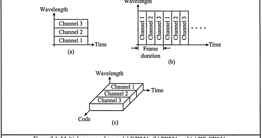
3.1.1 Wavelength-division multiple-access...32
3.1.2 Time-division m ultiple-access... 32
3.2 Code-Division Multiple-Access... 34
3.2.1 Spread-spectrum...34
3.2.2 DS and FH spread-spectrum techniques... 36
3.2.3 Spreading sequence...38
3.2.4 Correlation... 39
3.2.5 Synchronisation...41
3.2.5.1 pream ble...43
3.3 Sum m ary... 45
Chapter 4. SPREADING CODES... 46
4.1 Introduction...46
-4.2 {n,w,Xa,Xc) Optical Orthogonal Codes...50
4.2.1 Proposed algorithm...53
4.2.1.1 definition...53
4 .2 .2 Proposed (n,3xK,K,K.) O O C ... 61
4.3 («, w ,l,l) Strict O O C ... 62
4.4 Prime Codes (PC )...63
4.4.1 Prime-sequences...64
4.4.2 M odified prime codes (M PR)...64
4.4.2.1 quasi-prime sequences...65
4.4.2.2 2” prim e-sequences...65
4.4.2.3 extended prime-sequences...67
4.4.2.4 2n extended prim e-sequences...67
4.5 Other O OC...67
4.6 Discussions...68
4.7 Sum m ary... 73
Chapter 5. DIRECT-SEQUENCE CDMA SYSTEMS...75
5.1 Introduction... 75
5.2 T ransm itter... 76
5.2.1 Encoder employing m ultiplier...77
5.2.2 Encoder employing tap-delay structure...78
5.3 Channel Characteristics...80
5.4 Receiver... 81
5.4.1 Decoder employing multiplier - Correlator...81
5.4.2 Decoder employing tap-delay structure - Matched filter...83
5.5 DS-CDMA Operating Modes...86
5.6 Comparison of Correlator and MF Receivers...88
5.6.1 Case 1 - M inimum dispersion effect...88
5.6.2 Case 2 - Severe dispersion effect... 91
5.6.3 Case 3 - Near-far effect...94
5.7 OOK-CDMA... 96
5.8 PPM-CDMA... 98
5.9 Hybrid PPM-CDMA...99
5.10 Sum m ary...104
Chapter 6. HYBRID PIM-CDMA SYSTEM... 105
6.1 Introduction... 105
6.2 Hybrid PIM-CDMA... 106
6.3 Comparison of DS-CDMA systems... 113
6.4 Sum m ary... 126
Chapter 7. ERROR RATE ANALYSIS OF /*PIM-CDMA...127
7.1 Introduction...127
7.2 Analysis of Asynchronous /iPIM-CDMA...128
7.2.1 Results and discussions... 145
7.3 Gaussian Approximation...156
7.3.1 Gaussian approximation to the binomial distribution... 156
7.3.2 OOK-CDM A ... 160
7.3.3 Hybrid cdma system s...166
Chapter 8. CONCLUSIONS AND FURTHER W O RK ...171
8.1 Conclusions...171
8.2 Further W ork... 173
Appendix. COMPUTER PROGRAMS FOR PROPOSED ALGORITHM ... 176
REFERENCES...179
SOFTWARE (1 CD)... 189
-GLOSSARY OF ABBREVIATIONS
Abbreviation
Description
AM Amplitude modulation BEF Bit-rate-enhancement factor BER Bit-error-rate
CCD Charge-couple-devices CDMA Code-division multiple-access CD Compact disc
CMOS Complementary metal oxide semiconductor
CW Codeword
DC Direct current
DFE Decision-feedback equaliser
DPPM Differential pulse position modulation DS Direct-sequence
DSSS Direct-sequence spread spectrum EPS(P) Extended prime-sequence (P) ERD Extended-relative-distance
FDMA Frequency-division multiple-access FH Frequency-hopping
FHSS Frequency-hopping spread spectrum FM Frequency modulation
FOV Field of view
^PIM-CDMA Hybrid pulse interval modulation - code-division multiple-access /iPPM-CDMA Hybrid pulse position modulation - code-division multiple-access IEEE Institute of Electrical and Electronics Engineers
IID Independent, identically distributed IM/DD Intensity modulation with direct detection IR Infrared
ISI Inter-symbol interference ISM Industrial, scientific and medical LED Light-emitting diode
LOS Line-of-sight LPF Low pass filter
MAI Multiple-access-interference MF Matched filter
MPR Modified prime codes
OOC Optical orthogonal codes OOK On-off keying
PC Prime codes
PCM Pulse code modulation PDF Probability density function PER Packet-error-rate
PHY Physical
PIM Pulse interval modulation PLL Phase-lock-loop
PM Phase modulation PN Pseudonoise
PPM Pulse position modulation PS(P) Prime-sequence (P) QC Quadratic congruence QF Quantisation feedback QPS(P) Quasi-prime sequence (P) RD Relative-distance
RF Radio frequency RMS Root-mean-square SER Symbol-error-rate
SIR Signal-to-interference ratio SNR Signal-to-noise ratio
SOOC Strict optical orthogonal code TC Truncated Costas
TDMA Time-division multiple-access WDMA Wavelength-division multiple-access WLAN Wireless local area network
-GLOSSARY OF SYMBOLS
Abbreviation
a A “h b^Tx
(
05
b Tx(t)bRx{t)’
^/fcc(0
^ k \T x ’ B k \Tx
D . Dl
n k \R x ’ k \R x
BEFModulation 1
Modulation 2
BEF op
CCom
cL 'code'
C W ( U )
C
'C
0
de„'cw(Qw
^ R x ( 0 ’ d / t x ( 0
d Tx ( 0
DL\Spread
DRMS
D/?A/S| Modulation
DSignal
DSpread
DSpread\ min
Description
Number of program lines Ampere
Constant related to RMS delay spread Number of machine codes
Output signal of modulator; Output signal of modulator of the i* transmitter
Input signal to demodulator; Input signal to demodulator of the /th receiver
Binary data from information source; Binary data from information source of the Ith transmitter
Binary data to information processor; Binary data to the zth information processor
Bit-rate-enhancement factor o f ‘Modulation 1’ over ‘Modulation 2’
Optimum bit-rate-enhancement factor Computer clock frequency
Speed of light Code name Element of
Capacitance Codeword matrix
Photocurrent; Generated photocurrent by the photodiode of the Ith
receiver
Output signal of encoder of the ith transmitter
Maximum length of spread distance, measured between two correlated pulses of minimum spread distance and maximum spread distance, respectively
Channel RMS delay spread
Channel RMS delay spread of ‘Modulation’ signal
Spread distance of correlated signal pulse
Spread distance of a correlated pulse
Maximum spread distance of a correlated pulse
Normalised delay spread; Normalised delay spread of ‘Modulation’ signal
Minimum normalised delay spread with signal dispersion of 0.3TC or less
Normalised delay spread of 0.37^ signal dispersion
Power of optical source or channel input signal; Optical signal transmitted by the /th transmitter
Output signal of multiplier of the ixh correlator receiver, or output signal of tap-delay structure of the Ith MF receiver
Element of ' ^ E R D f c ^
Extended-relative-distance matrix
Number of system clients or users Square pulse
A square pulse of Tb
A square pulse of Tc
Optical gain of channel; optical channel gain of the signal from the 7th transmitter to the /th receiver
Effective channel impulse response - normalised; Effective channel impulse response of the signal from the 7th transmitter to the ith receiver Channel impulse response for a given value ah
Effective height of the ceiling above optical source and detector
Variable related to the numbering of client (or user) or the row index of matrix
Variable related to the numbering of client (or user) or the row index of matrix
Variable related to the column index of matrix Variable related to the column index of matrix Bit or symbol sequence number
Order of cascading codewords
Number of symbol sequence of one less than k
Number of symbols or order of PIM and PPM Average PIM symbol length
n Signature sequence length
n(t) Shot noise
n A positive integer related to the code weight of 2” PS(P)
nmid Mid value of sequence length
P Probability of success
P Prime number
PB BER\Moduiation Probability of bit-error-rate, obtained using Binomial function, of ‘Modulation’ scheme
PB E Probability of error obtained using Binomial function
PB MAi\Moduiation Probability of a false alarm occurring in a single chip, obtained using
Binomial function, due to MAI (as a result of cross-correlation), of ‘Modulation’ scheme
Pb set/{Modulation Probability of a false alarm occurring in a single chip, obtained using
Binomial function, due to self interference (as a result of auto correlation), of ‘Modulation’ scheme
^CFA\Moduiation Probability of a false alarm occurring in a single chip position of ‘Modulation’ scheme
PG E Probability of error obtained using Gaussian function
BER\Moduiation Probability of bit-error-rate, obtained using Gaussian function, of ‘Modulation’ scheme
PNS\Moduiation Probability of a new symbol will occur of ‘Modulation’ scheme
^ser|Modulation Probability of symbol-error-rate of ‘Modulation’ scheme
PSFA\Moduiation Probability of a symbol, with y slots, in error due false alarm of ‘Modulation’ scheme
P\SFA\Modu!ation Probability of one symbol in error due to false alarm
P2sFA\Moduiation Probability of two consecutive symbols in error due to false alarm
Pk \Modulatioa Probability of self-interference (due to auto-correlation) of ‘Modulation’ scheme
P*. \Moduiation Probability of one other user interference (due to cross-correlation) of ‘Modulation’ scheme
PDFb Probability density function obtained using Binomial function
PDFb MAI\Modulation Probability density function due to MAI, obtained using Binomial
function, of ‘Modulation’ scheme
PDF,G.MAl\Modulation
PDFSl\Modulation,
^ ^ F s i | Modulation
q
q
Q
r d ( u )
R
R b ’ R ^Modulation
Rc
^c|0.3
Rrx5Rrx
Rs
Rtx » Rtx
'code' n r'k Fxw r d,\")
s
S[ •'LW4(0
t Tb Tc T_10.3 EP' S\Modulation
Probability density function due to MAI, obtained using Gaussian function, of ‘Modulation’ scheme
Probability density function due to a single user interference of ‘Modulation’ scheme
Probability density function due to the Ith user interference of
‘Modulation’ scheme
Probability of failure. The complement of p
Order of cyclically shifting the frames of PS(P) codeword to the left Code weight of QPS(P)
Element of
Resistance
Bit rate; Bit rate of ‘Modulation’ scheme
Chip rate
Chip rate limited by DT^0 3
Photodetector responsivity; Photodetector responsivity of the ixh receiver
Slot rate
Optical source responsivity; Optical source responsivity of the f 1
transmitter
Relative-distance matrix
Seconds Sum
A decimal integer, corresponding to M bits of information being mapped, of the &th symbol of the fth data source
Output signal (signature sequence) of code register of the Ith receiver
Output signal (signature sequence) of code register of the Ith transmitter
Time Bit duration Chip duration
Chip duration related to normalised delay spread of 0.3
Effective pulse duration Slot duration
Symbol duration of ‘Modulation’ signal
Time duration
-Total Total u{t) V Vb Vd Vp V, v,h Vt W W Arr Com
w.
ave\Modulationw.
ave\Rxw.
avel Txw ModulationModulationX2 K
wP
X Xr, X Xky
z
zBEF •NS S(x) yTotal of possible arrangements of e r d ^ values
Estimated total computing time Unit step function
Volt
Peak voltage of modulator output signal Peak voltage of encoder output signal Signal peak voltage
Peak voltage of code register output signal Threshold level
Peak voltage of threshold detector output signal Code weight of OOC
Watt
Average optical power of ‘Modulation’ signal
Received average optical power
Average intensity or optical power of transmitted signal
Power efficiency; Power efficiency of ‘Modulation 1 ’ over ‘Modulation
2’
Maximum optical transmit power Peak optical power
Temporary variable
Integer random variable of Binomial function
Random variable, of real number, of Gaussian function No of trials
Redundant chips of the kth symbol Temporary variable
Temporary variable
Ratio of the sequence length over the information length, where the optimum BEF is achieved
Ratio of the sequence length over the information length, where a symbol being divided into two (worst case) will occur. It also denotes the number of symbols that a false alarm must occur consecutively before a new symbol is generated
r M
P MAl\OOK-CDMA
<J
2
MAl\OOK-CDMA
T d\Tx
T d\Rx
Ti t SP\C
K
x .
Xx and X2
Average information slots Mean
Mean of OOK-CDMA considering MAI only
Standard deviation
Variance of OOK-CDMA considering MAI only
Transmission time delay of the zth transmitter
Receiving time delay of the zth receiver
Centre time shift of dispersed signal pulse, where most power is concentrated, recovered at the zth receiver
Auto-correlation constraint Cross-correlation constraint Optical wavelength 1 and 2
-LIST OF FIGURES
Figure 1.1: Optical wireless DS-CDMA system block diagram and contents of thesis in
summary... 5
Figure 2.1: IM/DD base optical system block diagram... 14
Figure 2.2: Optical wireless system link configurations... 16
Figure 2.3: Diffuse link channel model...18
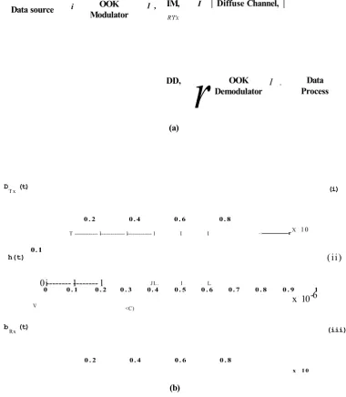
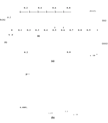
Figure 2.4: OOK diffuse system, (a) block diagram, (b) waveforms; (i) transmitter output, (ii) effective impulse response (using (2.8)), where D ^ = O.SxlO^s, Rb = 1 Mb/s, d t\ook = 0-3 (using 2.7)), Goc =1 and RjxRrx = 1, and (iii) receiver input, (c) enlarged section of single pulse in (b) (iii)...22
Figure 2.5: PPM symbol mapping 4-bits information Bk^Tx ={l 0 1 0}...23
Figure 2.6: 16-PPM diffuse system, (a) waveforms, symbol duration is 4xl0-6s ; (i) transmitter output, (ii) effective impulse response, where Dm s =0.3xl0“6s , Rs = \/Ts = 4 Mb/s , d t\ppm = 1-2 > Goc = 1 and RtxRrx = 1 j and (iii) receiver input, (b) enlarged section of single pulse in (a) (iii)...24
Figure 2.7: PIM symbol mapping 4-bits information Bk^Tx = {l 0 1 0}...25
Figure 2.8: 16-PIM diffuse system signal waveforms, symbol duration is 4x l0 _6s ; (i) transmitter output, (ii) effective impulse response, where Dm s = 0.3xl0_6s , Rs = 1/Ts = 4 Mb/s , DTjPIM = 1.2, Goc = 1 and R ^ R ^ = 1, and (iii) receiver input... 26
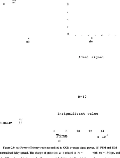
Figure 2.9: (a) Power efficiency ratio normalised to OOK average signal power, (b) PPM and Ttrrp / PIM normalised delay spread. The change of pulse slot Ts is related to Ts = % with Rb = 1 Mbps, and the diffuse channel is characterised by Dm s = 0.3x 10_6s . (c) Signals’ dispersed shapes due to DT in (b), where Ts = lx l0 -6 s and Dm s varies as DT varies. 28 Figure 2.10: BEF performance of PIM over OOK and PPM...29
Figure 3.1: Multiple access schemes, (a) WDMA, (b) TDMA and (c) DS-CDMA... 34
Figure 3.2: DS-CDMA encoding technique at Rb - 1 Mbps and Rc =5 Mbps. (a) optical signal (unipolar), (b) electrical signal (bipolar); (i) is the information signal, (ii) is spreading sequence of pattern {l 0 1 0 0} repeating at every \/Rb duration, and (iii) is resulting waveform... 37
Figure 3.3: A typical FH sequence for one bit period...38
Figure 3.4: A typical correlator block diagram...39 Figure 3.5: Correlation process of two identical sequences or auto-correlation; (a) and (b) are in-
phase, and (c) and (d) are out-of-phase, (a) and (c) are optical signals, and (b) and (d) are
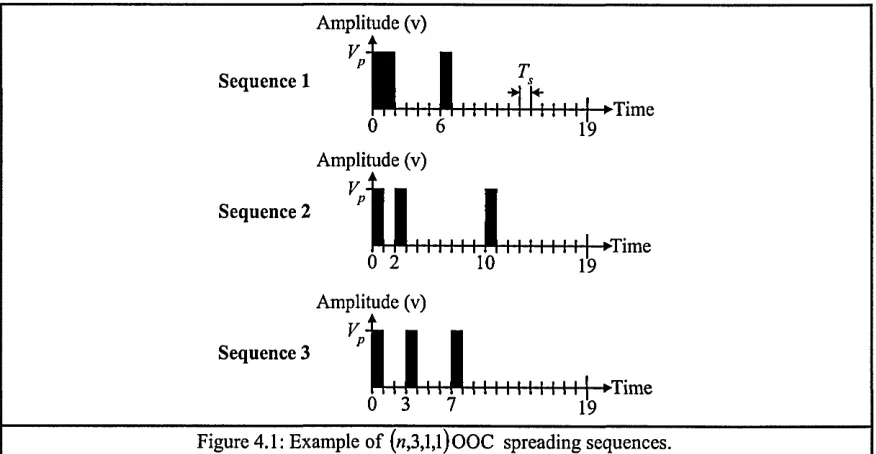
-electrical signals, (i) is transmitted or received signal, (ii) is replica sequence at receiver and (iii) is resulting waveform of mixer... 41 Figure 3.6: Illustration of rough and fine synchronisation for DS-CDMA system...42 Figure 3.7: Joint multiple-access techniques...45 Figure 4.1: Example of («,3,l,l)OOC spreading sequences...48 Figure 4.2: Flow chart for recursive algorithm...52 Figure 5.1: Optical DS-CDMA system block diagram...75 Figure 5.2: Transmitter block diagram of optical wireless DS-CDMA employing multiplier as
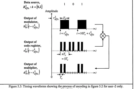
encoder...76 Figure 5.3: Timing waveforms showing the process of encoding in figure 5.2 for user-2 only.. 78 Figure 5.4: Transmitter block diagram of optical wireless DS-CDMA employing tap-delay
structure as encoder...78 Figure 5.5: Timing waveforms showing the process of encoding in figure 5.4 for user-2 only.. 80 Figure 5.6: Diffuse optical wireless DS-CDMA system link channel model...81 Figure 5.7: Receiver block diagram of optical wireless DS-CDMA employing correlator 82 Figure 5.8: Sample waveforms observed from figure 5.7 for user-2 only... 83 Figure 5.9: Receiver block diagram of optical wireless DS-CDMA employing matched filter.. 84 Figure 5.10: Sample waveforms observed from figure 5.9 for user-2 only... 86 Figure 5.11: Synchronisation technique employing a base station for global synchronisation at
the clock rate Rc [ARRL91]...87 Figure 5.12: Sample waveforms for minimum dispersion case; (i) user-1 transmitted signal, (ii)
user-2 transmitted signal and (iii) user-2 photo-detector output d ^ t )... 89 Figure 5.13: Sample waveforms of correlator for minimum dispersion case...90 Figure 5.14: Sample waveforms of MF for minimum dispersion case... 91 Figure 5.15: Sample waveforms for severe dispersion case; (i) user-1 transmitted signal, (ii)
user-2 transmitted signal and (iii) user-2 photo-detector output d l i t )... 92 Figure 5.16: Sample waveforms of correlator for severe dispersion case...93 Figure 5.17: Sample waveforms of MF for severe dispersion case...93 Figure 5.18: Sample waveforms for near-far effect case; (i) user-1 transmitted signal, (ii) user-2
transmitted signal and (iii) user-2 photo-detector output </**(*)...94 Figure 5.19: Sample waveforms of correlator for near-far effect case...95 Figure 5.20: Sample waveforms of MF for near-far effect case... 96 Figure 5.21: BEF performance, of OOK-CDMA normalised to OOK, against F and w...97 Figure 5.22: Power efficiency performance, of OOK-CDMA normalised to OOK, against F
and w ...97 Figure 5.23: 4-PPM-CDMA signal stream of 2 symbols mapping information
5*|r,={' 0 0 0 ...98
-Figure 5.24: 4-/zPPM-CDMA signal stream of 2 symbols mapping information
0 0 99
Figure 5.25: BEF performance, of ^PPM-CDMA normalised to OOK-CDMA, against F and
M for w = 3,5, and 8 ... 102 Figure 5.26: Power efficiency performance, of /zPPM-CDMA normalised to OOK-CDMA,
against F and M for w = 3,5 and 8 ...103 Figure 6.1: 4-/zPIM-CDMA signal stream of 2 symbols mapping information
B k \ T x = i l 0 0 l )...1 0 6
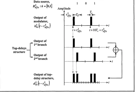
Figure 6.2: //PIM-CDMA; (a) transmitter block diagram, (b) receiver block diagram and (c) timing waveforms showing the process of encoding... 108 Figure 6.3: /zPIM-CDMA signal demodulation...109 Figure 6.4: BEF performance, of /zPIM-CDMA normalised to /zPPM-CDMA, against F and M
for Tv = 3,5 and 8 ...I l l
Figure 6.5: Power efficiency performance, of /zPIM-CDMA normalised to /zPPM-CDMA, against F and M for tv = 3,5 and 8 ...112 Figure 6.6: Power efficiency performance normalised to OOK, against F and M for w = 8. 115 Figure 6.7: Power efficiency performance normalised to OOK, against F and tv for M = 4.116 Figure 6.8: BEF performance normalised to OOK, against F and M for tv = 8 ...118 Figure 6.9: BEF performance normalised to OOK, against F and tv for M = 4 ...119 Figure 6.10: BEF performance, of /zPIM-CDMA normalised to OOK, against F and M for
Tv = 3,5 and 8 ...120
Figure 6.11: The ratio of sequence length over information length of optimum BEF, of /zPIM-CDMA system...121 Figure 6.12: Power efficiency performance, of /zPIM-CDMA and OOK-CDMA employing
PS(P) and normalised to OOK, against F and/or tv...122 Figure 6.13: BEF performance, of/zPIM-CDMA and OOK-CDMA employing PS(P) and
normalised to OOK, against F and/or tv and M ... 124 Figure 6.14: BEF performance, of /zPIM-CDMA employing PS (P) and optimal (n,8,l,l)OOC
and normalised to OOK, against F and/or tv and M ... 125 Figure 7.1: Auto-correlation constraints of (5,2,l,l)S00C...130 Figure 7.2: Illustration for error occurrence; (a) for PIM (b) for /zPIM-CDMA...133 Figure 7.3: Illustration of the probability a /zPIM-CDMA symbol being divided into two; (a)
n = 5 and M = 3, and (b) n = 5 and M = 2...134 Figure 7.4: The Pns\hpim-cdma for/zPIM-CDMA employing optimal (w,3,l,l)SOOC; (a)
Figure 7.5: The PNS\hPiM-CDMA f°r ^PIM-CDMA employing optimal («,5,l,l)SOOC; (a)
PNs\hpm-cDMA aSainst F and M , and (b) zNS corresponding to PNS\hP1M_CDMA...137
Figure 7.6: The PNS\hPiM-cDMA f°r ^PIM-CDMA employing optimal («,8,l,l)SOOC; (a)
PNs\hpm-cDMA a8ainst F and M , and (b) zNS corresponding to PNS\hpIM-CDMA...138
Figure 7.7: Probabilities of one symbol and two consecutive symbols being in error, against F
and w... 142 Figure 7.8: Sequence of /zPPM-CDMA symbols with and without false alarm pulse for n = 5
and M = 2 ... 143 Figure 7.9: BER performance of OOK-CDMA, /zPIM-CDMA and ^PPM-CDMA, against F
and w...146 Figure 7.10: Values of M ; (a) for ^PIM-CDMA due to condition zNS = 30, and (b) for
/zPPM-CDMA when BEF is optimum...147 Figure 7.11: BER performance of /*PIM-CDMA, ^PPM-CDMA and OOK-CDMA, against F
for w = 3,5 and 8 ... 148 Figure 7.12: BEF performance, of ^PIM-CDMA and /zPPM-CDMA normalised to
OOK-CDMA, against F and w for values of M corresponding to figure 7.10... 150 Figure 7.13: BER performance of APIM-CDMA, APPM-CDMA and OOK-CDMA; (a) against
F and w , for M = 2, and (b) against F, for w = 3,5 and 8 and M = 2 ...152 Figure 7.14: BEF performance, of ^PIM-CDMA and /iPPM-CDMA normalised to
OOK-CDMA, against F and w for M = 2...153 Figure 7.15: BER performance of /zPIM-CDMA, /iPPM-CDMA and OOK-CDMA; (a) against
F and w, for M = 4, and (b) against F, for w = 3,5 and 8 and M = 4... 154 Figure 7.16: BEF performance, of ^PIM-CDMA and ^PPM-CDMA normalised to
OOK-CDMA, against F and w for M = 4... 155 Figure 7.17: Graphical representation conveying the conditions of Binomial distribution to be
close approximated by the Gaussian distribution... 158 Figure 7.18: Graphical demonstration of Binomial distribution in relation to the Gaussian
distribution based on the conditions (7.35) and (7.36)...159 Figure 7.19: PDF and BER plots for OOK-CDMA. (a) and (c) are PDF. (b) and (d) are BER. (a)
and (b) are obtained using («,4,l,l)OOC. (c) and (d) are obtained using («,8,l,l)OOC.... 163 Figure 7.20: PDF and BER plots for OOK-CDMA employing optimal (l211,1 l,l,l)OOC and
P S (ll)...165 Figure A.l: Program structure of the proposed algorithm and other utilities programs... 178
-LIST OF TABLES
Table 2.1: Comparison between RF and IR for indoor wireless communications...15 Table 4.1: Various combination values of mfyq and erd^2)...57 Table 4.2: Possible arrangements in every row of ERD for F = 5 ...70 Table 4.3: Comparison between theoretical and practical results of computational time require
to obtain for valid sets of codewords using proposed recursive algorithm...72 Table 6.1: Power efficiency and BEF expressions for various DS-CDMA schemes normalised to OOK... 114 Table 7.1: Conditions tests for OOK-CDMA employing optimal («, w,l,l)OOC... 161 Table 7.2: Conditions for the Gaussian distribution to approximate MAI distribution of three
CDMA systems... 169
-Chapter 1
INTRODUCTION
The study of infrared frequencies for short-range wireless communications has received
extensive interest over the past decade. It started from the proposition and demonstration of the
diffuse infrared (IR) radiation for wireless in-house data communication, which was first
introduced by Gfeller and Bapst in 1979 [Gfeller79]. Since then there has been a number of
research interests in IR frequency for wireless local-area-networks (WLANs) in place of the
well-established radio frequency (RF) systems [Yen85, Barry93, Carruthers96b, Tanaka97,
Yu02, Sidorovich02, Al-Ghamdi03, Giakos03]. The advantages of using IR frequency over RF
for short-range wireless communications are as follow [Marsh96, Kahn97]:
• IR emitters and detectors capable of high-speed operation are available at low cost,
are relatively simple to design circuits with and are physically small in size
compared to their RF counterparts
• The RF spectrum is already extremely congested and bandwidth allocation is
limited. Compared with IR frequency, which offers a huge unregulated bandwidth,
allows manufacturers to design one product that can be used in any country
worldwide, thus avoiding costly “market specific” designs and the need for
licensing
• The fact that IR frequencies cannot penetrate the boundaries of the room from
which they originate makes wireless infrared inherently secure. This gives an
-additional advantage in that similar systems may be operated in adjacent rooms
without interference
To improve the quality of transmission and reception of wireless IR communication systems, a
number of modulation techniques have been introduced. Of all these techniques, On-Off Keying
(OOK) is the simplest to implement, and has been used in a number of high-speed prototype
systems [McCullagh94, Audeh96]. The use of a power efficient modulation scheme, such as
Pulse Position Modulation (PPM), offers a decrease in the average power requirement compared
with OOK [Kaluarachi96a] but at the cost of increased bandwidth. Pulse Interval Modulation
(PIM) technique, being investigated at the Sheffield Hallam University over the past nine years,
has been suggested as a possible alternative to PPM for optical wireless communication
systems. Compared with PPM, PIM has a higher transmission capacity by virtue of its
anisochronous nature, and requires no complex symbol synchronisation at the receiver
[Ghassemlooy98a, Hayes98].
As in RF wireless systems, diffuse IR wireless systems can employ a multiple access scheme
for channel reuse strategy. The Direct-Sequence Code-Division Multiple-Access (DS-CDMA)
is one promising scheme, which operates in both the time and wavelength domains, can enhance
the channel capacity when the wavelength resource is constrained. However, this is achieved at
the cost of reduced data throughput. A DS-CDMA system employing OOK signal format,
which is also known as OOK-CDMA, was first introduced for fibre optic systems by
[Salehi89a, Salehi89c]. It utilises optical orthogonal codes (OOC) to form signature sequences
for the purpose of message separation. OOC are sets of zero and one sequences with good auto-
and cross-correlation properties, i.e., the auto-correlation of each sequence exhibits a
“thumbtack” shape (a pulse of high amplitude at zero shift and pulses of low amplitudes at other
shifts) and the cross-correlation between any two sequences produces pulses of low amplitudes
throughout. The use of OOC enables a large number of asynchronous users to transmit
detection of the desired signal, and the low cross-correlation reduces interference from
unwanted signals in the network [Chung89].
Generally, a DS-CDMA system encoding is carried out by “spreading” individual bits to form a
signature sequence with a higher bandwidth. However, the bandwidth of an IR diffuse wireless
system is limited by characteristics of the channel (due to the room dimensions) the system
operates in. Under such a bandwidth constraint, a DS-CDMA system’s throughput is reduced,
which is inversely proportional to the length of the signature sequence. For example, the
throughput of OOK-CDMA system is lower than an OOK system under limited bandwidth. To
improve a DS-CDMA system’s throughput without increasing the bandwidth, hybrid PPM-
CDMA (/zPPM-CDMA) system (i.e. DS-CDMA system employing PPM technique) has been
proposed to enhance the data rate based on the property of PPM technique to perform data
compression [Elmirghani94]. In addition, it is found that the throughput can be further enhanced
using a /zPIM-CDMA system, where PIM technique offer better data compression. APIM-
CDMA system design is also simpler in that the signal is anisochronous and hence no symbol
synchronisation is required compared with the OOK-CDMA and /zPPM-CDMA systems.
Both /zPIM-CDMA and /zPPM-CDMA systems achieve data compression by transmitting a
shorter symbol than OOK-CDMA. On the other hand, a symbol of shorter duration will affect
the performance of both hybrid systems in terms of bit-error-rate (BER) and power efficiency as
the signal power per symbol has been condensed. Moreover, the total signal power allowed to
transmit to the channel is limited by the eye safety regulations where the signal power, in
average, shall not exceed the critical level that can damage the retina of eye. These criterions
impose challenges to the design of /iPIM-CDMA, and /jPPM-CDMA, for use in IR diffuse
wireless systems. However, with careful design and employing OOC with good correlation
properties, which is the main focus of this work, the /iPIM-CDMA system performance can be
improved and can be considered as a potential candidate for the IR diffuse wireless systems for
1.1 Research Objectives
In order to achieve the above mentioned, a number of research objectives have been identified as outlined below:
• Comprehensive literature survey of indoor optical wireless communication systems. Acquire an understanding of the IR diffuse channel characteristics and identify the constraints that it imposes. Review the various modulation techniques employed, such
as the OOK, PPM and PIM, to improve systems performances under the constraints identified
• Review the multiple-access schemes that can be efficiently used in IR diffuse wireless systems and identify the advantages and disadvantages compared with the RF systems. Investigate the DS-CDMA systems employed in the electrical domain, the changes that are required to the system design when migrating to the optical domain
• Review the correlation properties of OOC for message separation. Perform a literature survey of the various proposed OOC for use in optical DS-CDMA systems. Develop a new algorithm that can be used to construct large sets of OOC with good correlation properties, that is practical to implement and requires minimal computation time
• Review the fundamental properties of a conventional optical wireless DS-CDMA system, which is the OOK-CDMA. Understand the system design and how the signature sequence encoding and decoding are carried out in the encoder and decoder, respectively. Examine the performance OOK-CDMA under the constraints imposed by an IR diffuse wireless system
• Perform a literature survey of optical wireless DS-CDMA systems over a range of
modulation techniques. Investigate the hardware and configurations for designing the
-proposed /zPIM-CDMA system. Examine the performance of a /zPIM-CDMA system
under the constraints of an IR diffuse wireless channel and compare with OOK-CDMA
and /zPPM-CDMA systems
1.2 Organisation of Thesis
A general block diagram of an optical wireless DS-CDMA system is shown in figure
1.1. To present this work, the thesis is divided into 8 chapters and the contents of this thesis are
summarised with reference to the system blocks in figure 1.1.
I IR Diffuse '
BER Data
Source ProcessData
OOC Source OOC
Source Signal
Modulator EncoderCDMA DecoderCDMA DemodulatorSignal
Chapter 1
- Introduction to thesis
Chapter 2
- Introduction and review of RF & IR wireless systems and modulation techniques - Characterisation
and modelling of diffuse channel - Discussions and
comparisons of modulations techniques their power and bandwidth
efficiencies
Chanter 3
- Introduction and review of multiple-access schemes - Further study of
CDMA system employing DS or FS modulation technique - Evaluation of
DS-CDMA and FH-CDMA for use in optical wireless system
Chapter 4
- Introduction to various OOC - Proposed a
novel recursive algorithm for constructing large set of (n,3,1,1) OOC in the quickest time possible - Discussion of
recursive and algebraic algorithms
Chapter 5
- Detailed study of DS- CDMA system employing OOK signal format
- Review of DS-CDMA system encoders and decoders properties and configurations - Examine DS-CDMA
systems performances in terms of data throughput and power efficiencies due to bandwidth constraint - Review of DS-CDMA
system employing various modulation techniques
Chapter 6
- Introduction to /iPIM-CDMA system and review of its codeword properties - Compare ZiPIM-
CDMA system throughput and power effiencies with OOK, OOK- CDMA and APPM-CDMA systems due to bandwidth
constraint
Chapter 7
- Derived BER expression (Binomial function) for /?PIM-CDMA and /iPPM-CDMA - Evaluate and
compare BERs for /iPIM-CDMA, OOK-CDMA and WPM-CDMA - Examine the
application of Gaussian function for approximating BER
Chapter 8
- Conclusions of thesis and further work
Figure 1.1: Optical wireless DS-CDMA system block diagram and contents of thesis in summary.
Following chapter 1, chapter 2 provides a review of the current RF and IR wireless
communication systems. The chapter will begin with the introduction to RF wireless
communication systems and identifies the advantages and disadvantages. IR wireless
communication systems are then introduced and compared with the RF wireless systems. A
-general introduction to indoor optical wireless links is presented concentrating on the most viable link for a multiple-access communication system - using a diffuse link. The properties of an indoor diffuse IR channel are described and methods of modelling and characterising the channel are reviewed. Next the OOK, PPM and PIM modulation techniques are discussed and compared in terms of their efficiency under the constraints of a diffuse link.
Chapter 3 presents an evaluation of multiple-access schemes for use in optical wireless communication systems. The chapter focuses on the CDMA scheme, which utilises both the time and wavelength domains, as a candidate for the IR diffuse wireless system to enhance the network channel capacity efficiently. Modulation techniques such as direct-sequence (DS) and frequency-hopping (FH) techniques suitable for the CDMA systems are compared and evaluated for use in optical wireless systems.
In chapter 4, various OOC that have been proposed to date are presented and the algorithms, which can be categorised as either a recursive or algebraic, used for generating the codewords are discuss. A new recursive algorithm for generating larger sets of OOC codewords in the quickest time possible is proposed and results presented. The reasons a new algorithm is needed are discussed and the proposed algorithm is used as an example to demonstrate why a recursive algorithm always requires longer time than an algebraic algorithm for generating a large set of codewords.
In chapter 5, the procedures for signal modulation and demodulation,'and of signature sequence encoding and decoding for an optical DS-CDMA system employing OOK signal format, are
presented. There are two configurations for implementing the encoder and decoder, based on active or passive devices. The properties of the two configurations are reviewed. Then the optical DS-CDMA systems performances, under the bandwidth constraint of an IR diffuse wireless channel, are examined in terms of data throughput and power efficiencies. DS-CDMA systems employing various other modulation techniques proposed so far are reviewed.
-Chapter 6 presents the proposed /zPIM-CDMA scheme together with the codeword properties and the encoder-decoder configurations of the system. The data throughput and power efficiency of /zPIM-CDMA are compared with the OOK, OOK-CDMA and /zPPM-CDMA systems.
A comprehensive BER analysis of /zPIM-CDMA system is carried out in chapter 7. The analysis takes into account multiple-access-interference (MAI), self-interference and the hybrid nature of the /zPIM-CDMA signal detection. Also presented in this chapter is the BER expression for the /zPPM-CDMA system, which has not been previously reported. BER performances are
compared for /iPIM-CDMA, OOK-CDMA and /iPPM-CDMA. The use of Gaussian distribution
for DS-CDMA BER approximation is investigated. Usually, the assumption is made that the MAI is large in order to use the Gaussian approximation. However, it is found that the BER of
an optical DS-CDMA system (either OOK-CDMA, /zPIM-CDMA or /iPPM-CDMA) employing
certain groups of OOC is not close to a Gaussian approximation even when the MAI tends toward infinity. This is because there are two conditions that must be satisfied, which are discussed in this chapter.
1.3 Original Contributions
1. Analysis of IR diffuse wireless channel characteristics and the effect of the normalised delay spread due to the change of signal modulation bandwidth (sections 2.3.2 and 2.3.3).
2. Derivation of new expressions for representing the properties of a set of codewords using a standard matrix format, for the ease and convenient of referencing (section 4.1.1). A novel recursive algorithm for obtaining («,3,l,l)OOC is proposed and
implemented using the MATLAB programming language (section 4.2.1). The algorithm is equipped with well-refined conditions that help with computer programming and provides short cuts to the searching process for a valid set of codewords. The written programs are included in the CD.
3. Proposed («,3xK,K,K)OOC that can be constructed using the (w,3,l,l)OOC obtained
from the proposed algorithm (section 4.2.2).
4. Developed new expressions for obtaining the Prime Codes (PC) sequences using the representation of the standard matrix format (section 4.4). Investigated the disadvantage of the recursive algorithm compared with the algebraic algorithm - in the context of computation time required to generate a large set of codewords (section 4.6).
5. Developed mathematical models for the OOK-CDMA IR diffuse wireless systems employing active and passive devices for the encoder and decoder (sections 5.2, 5.3 and 5.4). Investigated the efficiency of active and passive devices when operating with unipolar signals. Investigated the upper bound of minimum normalised delay spread for an IR wireless DS-CDMA system. Developed an expression for a correlator receiver to
5.7). Derived mathematical models for a /zPPM-CDMA system and examined the appropriate configuration for its encoder and decoder (section 5.9).
6. Derived mathematical models for /zPIM-CDMA systems and examined the appropriate configuration for its encoder and decoder (sections 6.2). Investigated and compared the performances, in terms of data throughput enhancement and power efficiency, of /zPIM-
CDMA, OOK-CDMA, PPM-CDMA and APPM-CDMA under the constraints of a IR
diffuse wireless channel (section 6.3).
7. Developed a BER expression for the proposed /zPIM-CDMA system and the /zPPM- CDMA system (section 7.2). Demonstrated that the BER of /zPIM-CDMA, OOK- CDMA and /zPPM-CDMA employing (n,w,l,l)OOC can’t be approximated using a
Gaussian function (section 7.3).
-1.4 List of Publications
The work of this PhD has so far led to the publications listed below:
• C.K. See, Z.F. Ghassemlooy, J.M. Holding and R. McLaughlin, “Comparison of Binomial and Gaussian Distributions for Evaluating Optical DS-CDMA System BER Performance,” Proceedings of the Postgraduate Research Conference in Electronics. Photonics. Communications and Software Year 2003 fPREP 2003L University of Exeter (oral presentation) (14 - 16 April 2003), pl3-14.
• Z. Ghassemlooy, C.K. See, J.M. Holding and C. Lu, “Bit-Error-Rate Analysis for Hybrid PIM-CDMA Optical Wireless Communication Systems,” Microwave and Optical Technology Letters v31 nl (5 October 2001), p40-44.
• C.K. See, Z. Ghassemlooy and J.H. Holding, “Bit-Error Rate Analysis for PIM-CDMA Optical Wireless Communication Systems,” Proceeding of SPIE (oral presentation) v4214 (2001), pl53-161.
• C.K. See, Z. Ghassemlooy and J.M. Holding, “Hybrid PIM-CDMA for Optical Wireless Networks,” Proceeding of PGNET 2000. 1st Annual PostGraduate Symposium on the Convergence of Telecommunications. Networking and Broadcasting. John Moores University, Liverpool (oral presentation) (1 9 -2 0 June 2000), p i95-200.
-Chapter 2
REVIEW OF OPTICAL WIRELESS SYSTEMS
2.1 Introduction
This chapter will discuss the difference between RF wireless and optical wireless communication systems. The discussion will concentrate in particular on the need for exploring and developing optical wireless communication systems, for their capacity and efficiency, as an additional communication technique. This is motivated as a result of the bandwidth for the RF wireless systems is currently congested, which is the prime factor.
Both wireless systems require a modulation technique to transfer information to the destination. Section 2.2 will presents the fundamental need for a modulation technique for the RF wireless communication system. The advantages and disadvantages of radio frequency, which serves as the electromagnetic information carrier, are presented. One of the distinct disadvantages is that the RF spectrum is already congested and allocations of sufficient bandwidths are extremely
hard to obtain [Street97].
Communication between two devices could be in the range of short distance (i.e. less than 100 metres) or long distance. Short distance can be viewed as a communication between two terminal devices that requires wireless connection for the convenience of connection reconfiguration (i.e. ease of wiring problem) and short-range mobility - for example, a communication between two personal computer terminals within a room. Whereas, a long range communication involves high mobility and requires easy connection regardless of the communicators’ location - for example, a mobile phone link. RF can pass through walls and can
-travel long distances, whereas IR is a source of light and therefore does not pass through walls and stays confined within a room. RF may be more suitable for long-range and high mobility communications whereas IR could be used for short-range applications.
In section 2.3, the technique of using IR as an optical wireless communication carrier is presented. The difference between the modulations of RF and IR carriers, and their advantages and disadvantages are also discussed. Literature review of recent research and development in IR for indoor optical wireless communication systems and channel characteristics are presented. Section 2.4 will provide the comparison of OOK, PPM and PIM performances in a IR wireless system. Then it will discuss the motive behind study of the optical wireless communication and why PIM has been selected for this application. Summary is presented in section 2.5.
2.2 RF Wireless Communication Systems
Modulation is a process of converting information signals at a base-band frequency to a
new frequency, where the signal now occupies a spectral range known as the pass-band that can be accommodated by the channel medium. The pass-band signal in most electrical communication systems is usually a coherent continuous-wave. Modulation techniques such as the amplitude modulation (AM), frequency modulation (FM) and phase modulation (PM) are commonly used in radio communication systems, as they can employ simple coherent detection devices, such as a local oscillator, for demodulation. Each of these modulations requires a carrier wave to transport information at the frequency at least ten times higher than the base band frequency.
of channels can exist by dividing the available bandwidth of 83.5 MHz with each channel
having very narrow bandwidth, and with very narrow bandwidth separation. However, in practice, this is difficult to achieve due to limitation by the hardware capability.
Consequently, robust spread spectrum modulation techniques are required, which result in low data rates. As an example, the IEEE 802.11-1997 standard for WLANs physical (PHY) layer specifies that either the direct-sequence spread spectrum (DSSS) or the frequency-hopping spread spectrum (FHSS) be used (and or PPM for IR wireless system, this will be discussed later in section 2.3.3) [WWW2, IEEE97]. The data rate of the PHY layer is standardised to operate at either 1 Mbps or 2 Mbps at maximum. This was then improved upon in 1999 with the ratification of the IEEE 802.11b standard, which adds two higher data rates of 5.5 Mbps and 11Mbps to the DSSS standard [IEEE99]. Many of the products currently on the market today are either based on this standard, or the HomeRF standard, which also operates in the ISM band, and achieves a maximum data rate of 10 Mbps using FHSS. The next generation RF WLAN products operate in the so-called 5 GHz band that was allocated solely for use by WLAN products. This allows systems to be optimised in terms of data rate and efficiency, free from the constraints associated when coexisting with other products. There are currently two competing standards in this band, these being IEEE 802.11a and HiperLAN2, both of which provide maximum data rates of 54 Mbps. Another standard worth mentioning is Bluetooth, which is a short range point-to-multipoint standard for voice and data transfer, also operating in the ISM band. The data rate is a mere 723.2 kbps and can operate up to a range of 10 metres. Though
these are a few disadvantages of Bluetooth technology, the rationale behind it is low cost, thus allowing it to be integrated into a variety of portable electronics devices, which may then communicate with each other via ad hoc wireless networks termed piconets [Hayes02]. An experiment has been carried out to compare the performance between the DSSS and Bluetooth
systems and the results showed that the DSSS system performs better in the presence of interference [PunnooseOl].
-2.3 Optical Wireless Communication Systems
In an optical wireless system, the signal is transmitted over a channel at infrared frequencies using intensity modulation with direct detection (IM/DD). IM/DD is a simple process that takes place at the transmitter end and receiver front end, where an optical source such as an LED is used to convert an electrical current to an infrared intensity signal, and a photodiode is used to produce a photocurrent that is proportional to the infrared intensity that is incident upon it [Barry94]. At present, the IR spectrum is unregulated and the radiation does not produce visual interference, however it can harm the retina if the optical power is not carefully monitored. Infrared transmission eliminates the need for a radio carrier frequency as in the case of the electrical system discussed above, as the signal at base-band frequency can be directly modulated to IR frequency (pass-band) using the IM/DD technique [Kahn97, Shiu98a]. The use of radio carrier frequency in conjunction with IR can enable a multiple-access communication system, known as Orthogonal Frequency Division Multiplexing (OFDM) [You02].
One of the differences between an electrical (RF) signal and an optical (IR) signal is that an electrical signal can be bipolar and operates in both regions of positive and negative electric fields. Whereas an optical signal based on light intensity is always positive and unipolar. A schematic system block diagram of an IM/DD optical system is shown in figure 2.1. DC bias is included to ensure that the modulated signals are all positives prior to intensity modulation of the light source. At the receiver, the DC bias is removed from the detected signal before amplification and processing.
Information Signal
DC
Q.
*
ProcessingSignalFigure 2.1: IM/DD base optical system block diagram.
-Infrared is similar to visible light in that both are absorbed by opaque objects and do not pass through walls. In other words, an information signal carried by infrared is confined to the room in which it is originated. For this reason, the infrared frequency can be reused in the adjacent rooms with no regulation requirement, thus providing virtually unlimited transmission capacity [Kahn97]. Other comparisons between radio and infrared wireless systems, which have not been discussed above, are shown in table 2.1 [GhassemlooyOO, Barry94],
Property Radio Infrared Implication for infrared
Bandwidth regulated? Yes No Approval not required -
world-wide compatibility
Passes through walls? Yes No Inherently secure. Carrier
reuse in adjacent rooms
Multipath fading Yes No Simple link design
Multipath dispersion Yes Yes Problematic at high data rates
Path loss High High
Dominant noise Other users Background
light Short range Average power
proportional to J M ' F * J X w * hDTigxh (t)peak-average ratio is the input signal with
Table 2.1: Comparison between RF and IR for indoor wireless communications.
Although an optical system has the advantage over an electrical system such as it does not interfere with audio, microwave and other radio frequencies, its radiation, if not carefully controlled, could damage the human eye. Therefore, there is a need for a modulation technique that offers both power and bandwidth efficiencies. The following subsections will address these two issues and will introduce the modulation techniques suitable for IR applications.
2.3.1 Optical wireless link configurations
There are a number of ways that an optical wireless system can be configured, as shown in figure 2.2 [Barry94]. The line of sight (LOS) configurations (top row) achieve higher power efficiency than the non-LOS, as most of the transmitter radiation travels in one path to the receiver. Especially, the directed LOS configuration (figure 2.2 (a)) achieves the highest power efficiency by utilising narrow beam transmitter and narrow field of view (FOV) receiver. The concentrated light that is directed from the transmitter to the receiver makes this an optimum
-link with no multi-path propagation and ambient background light is largely rejected.
Nevertheless, the data rate is limited by the power budget due to eye safety regulations
[Smyth95]. All LOS communication links are susceptible to blocking in which their connections
are terminated by opaque objects that stand in between the transmitter and receiver. This is a
disadvantage of LOS configurations that limits their applications to point and
point-to-multipoint communication, but not for multiple access or mobile communications [Kahn97].
Directed Hybrid Non-directed
Line-of-sight
Non-line-of-sight
____________________ Figure 2.2: Optical wireless system link configurations._____________________
The non-LOS configurations (figure 2.2 bottom row) rely on walls, room objects or ceiling to
establish a link. The diffused infrared light, bearing the signal, will travel through many
different paths and undergo one or more reflections before reaching the receiver FOV. The
effect of such multi-path propagation maintains the communication linkage even when the LOS
is blocked, but suffer from optical power loss. On the other hand, multiple reflections will affect
the signal pulse being dispersed to the adjacent slot, causing inter-symbol interference (ISI). The
severity of pulse dispersion depends on the room dimension and the transmission bandwidth
[Gfeller79].
1 6
Fuller descriptions of each of the configurations shown in figure 2.2 have been presented in detail in [Barry94]. Here it was found that the diffuse system (figure 2.2 (f)), which is non directed non-LOS, is the most convenient from the user’s standpoint as the configuration does not require alignment between the transmitter and receiver, to maintain LOS allowing considerable mobility to communications. However it does suffer from multi-path propagation effects, however with careful design it has been experimentally proven that it has the capability to provide robustness and high-speed transmission [Marsh96]. The design involves using a large-area, wide FOV, narrow-band optical receiver to provide a high signal-to-noise ratio (SNR) in the presence of intense ambient illumination. It uses a high-pass filter to reduce the effect of fluorescent lights, and quantisation feedback (QF) to remove resulting baseline wander, with a decision-feedback equaliser (DFE) to mitigate ISI due to multi-path propagation [Marsh96, Lee98b, Lee98c]. From here on, this thesis will only consider the diffuse configuration.
2.3,1.1 diffuse system channel characteristics
A realistic infrared channel can be well characterised by two parameters, which are the optical path loss and the root-mean-square (RMS) delay spread. A diffuse channel can be modelled as a base-band linear system, with input power DTx(t), output current d ^ t ) , and an
impulse response h(t) which is fixed for a certain physical configuration of receiver, reflectors,
and transmitter [Kahn95, Carruthers96a, Carruthers97], as shown in figure 2.3. The model is summarised as:
(t) ® h(t)+n(t), ( z T f
where ® denotes convolution, is the receiver photo-detector responsivity with units (AAV)
and n(t) is channel noise with units (A) due to background radiation.
-Noise n t)
Optical power DtA ‘)
_________________________ Figure 2.3: Diffuse link channel model._________________________
To characterise a particular multi-path infrared channel, it is useful to determine the average transmitted optical power, given as:
_ _
= ’i s 2? J- TDjx ’ (2,2)
which is required to achieve a certain BER for a particular modulation scheme [Carruthers96a]. (2.2) is the power constraint and it implies that for a given transmitted average optical power Wave^Tx, the receiver SNR can be improved by transmitting a waveform DTx(t) having a high
peak-to-average ratio [Audeh94].
In [Carruthers97], the diffuse channel model definition is given as follows. Defining the optical
gain Goc for a channel with impulse response h(t) to be Goc = [ h{t)it, then the received
average optical power is:
^ave\Rx ~ ^OC^ave\Tx ' (2.3)
The optical path loss can be written as:
Optical path loss (optical dB) = - 101og10Go c. (2.4)
The transmitted optical signal after undergoing multiple reflections will cause pulse dispersion. The ceiling bounce model for multi-path dispersion is well represented by:
hc(^ah ) - ( \ 7 «(0. (2.5)
where ah = 2H jcL and u(t) is the unit step function. The variable H is the effective height of
the ceiling above the transmitter and receiver, and cL is the speed of light. The variable ah is related to the RMS delay spread by:
1 8
D«Ms(K(‘>a (2.6)
The normalised delay spread DT is a dimensionless parameter defined as:
Dt
EP (2.7)
where TEP is the effective pulse duration. This parameter can be used for investigating the
diffuse system performance due to the severity of pulse dispersion.
In the following, it is assumed that Goc = 1 when there is no power loss in channel. Thus the
effective channel impulse response is defined as:
j'hc(t,ah)dt —00
(2.8)
so that Goc = f h(t)dt = 1 [Carruthers96a]. J-00
2.3.2 Digital modulation techniques
To utilise a particular optical communication link, analogue signals are usually
converted into digital signals before being intensity modulated by a light source. The unipolar characteristic of optical system makes it more suitable to transmit digital signals than analogue ones. A pulse of peak intensity WP is transmitted to represent a ‘1’ and no intensity for a ‘O’.
There are several digital modulation techniques being proposed. In general, the choice of a modulation technique for a specific application is influenced by the characteristics of the message signal, the characteristics of the channel, the performance desired from the overall communication system, the use to be made of the transmitted data, and the cost factor, that is always important in practical applications [Tranter95]. The choice of a digital modulation technique for an indoor optical wireless communication is influenced by the eye safety regulations where the amount of optical shall not exceed the limit that will damage the human eye. The limit is defined as [Barry94]:
-1 T
1™“
J
(2.9)- T
where fVmax is the maximum allowable optical power transmitted for the duration of 2T. Other
influential issues include [Hayes02]:
• Power efficiency where power consumption is to be kept low while maintaining a desirable BER. Low power consumption will help to maintain a longer battery life for portable infrared devices.
• Bandwidth efficiency where the base-band bandwidth is limited by the multi-path
propagation effect in a diffuse system.
Digital modulation techniques that have been investigated for use in optical wireless system are OOK, PPM and PIM [Hayes02]. All these modulation techniques will be studied throughout this thesis with the assumption that information from data source is in a binary format.
2.3.2.1 on-off keying
It is the simplest modulation technique to implement. The modulation is a process of converting the information bit * 1 * from data source to a pulse of constant amplitude Vp for the
duration of one bit Tb. Whereas, the information bit ‘0’ is basically converted to an off state of
duration Tb. The data rate is Rb = l/Tb. The system block diagram is shown in figure 2.4 (a).
The waveforms observed at the input and output of the channel together with the channel impulse response is shown in figure 2.4 (b). As observed from figure 2.4 (b) and (c), the normalised delay spread for the OOK signal, denoted by DT^00K, represents the end point of the
exponential tail of the dispersed signal decay to an insignificant value. The value of DT\00K is
obtained by choosing Dm s = 0.3 x 10_6s , as an example, and the channel is assumed ideal with
no noise n(t).
-Denoting the binary data as Bk^Tx, the information bit stream at the output of OOK modulator is
represented by:
00
bTx(t) = Vp'Zi Bt\TiS{t-kTl,), (2.10)
k=0
where k is an integer denoting the k th bit information and g(^) is a square pulse. The optical
signal transmitted is given by:
^Tx^Txi^)’ (2.11)
where RTx is the transmitter optical source responsivity of unit (W/A).
2.3.2.2 pulse position modulation
PPM is an orthogonal modulation technique that has been proposed to achieve power efficiency compare with OOK, but at the expense of increase bandwidth and system complexity. In PPM, each block of M-bits of information is mapped to one of L possible symbols. Each
symbol is a fixed frame of duration LTS, where the time slot Ts = and L = 2M .
-Bk\Tx Wxi1) ®Tx {*)
/ 1
/'---Data source i ModulatorOOK 1 , IM, I | Diffuse Channel, |
R'I'x
DD, OOK I . Data
r
Demodulator Process(a)
D (t)T x (i)
0.1
h(t)
0 . 2 0. 4 0 . 6 0. 8