Vulnerability Analysis of Cyber Security Modelling
Language models using Probabilistic Logic
Rick Hindriks
[email protected]
Tuesday 6
thDecember, 2016
MSc Thesis - Final (r3452)
Supervisors
ABSTRACT
Computer systems are an essential asset of large companies such as banks, financial institutions, utility companies and telecommunication providers. Given their important roles for the functioning of society, these companies are under a constant threat of cyberattacks. Enterprises rely on the availability of these complex ICT systems for their day-to-day operations, and disruptions in the availability of these systems can have disastrous consequences. Given the growing complexity of the attacks and the growing size of network infrastructures, security experts require the use of automated tools to determine the security of their systems. To this end, we propose an automated method for the analysis of vulnerabilities within network architectures, based on the Cyber Security Modelling Language[35](CySeMoL). We aim to improve the time required for inferring the likelihood of a successful cyberattack in a given network infrastructure, based on the threat model defined by CySeMoL. We define an alternative implementation of the vulnerability analysis using Probabilistic Logic[17](ProbLog). By using a model-based approach to the analysis of CySeMoL, we provide an extensible method for the development of such an alternative analysis. We have succeeded in achieving this by using intermediate models which capture the threat model of CySeMoL and the definition of concrete network infrastructures. However, our measurements show that the proposed analysis method using ProbLog does not perform better than CySeMoL for larger models.
Keywords
Threat modelling, dynamic risk assessment, SEGRID, CySeMoL, P2AMF, attack trees, vulnerability
Preface
“Then, one day, a student who had been left to sweep up the lab after a particularly unsuccessful party found himself reasoning this way: If, he thought to himself, such a[Infinite Improbability Drive]is a virtual impossibility, then it must logically be a finite improbability. So all I have to do in order to make one is to work out exactly how improbable it is, feed that figure into the finite improbability generator, give it a fresh cup of really hot tea . . . and turn it on! He did this, and was rather startled to discover that he had managed to create the long sought after golden Infinite Improbability generator out of thin air.”
Discovery of the Infinite Improbability generator — Douglas Adams
This is the thesis for the final project of theComputer Sciencemaster programme with a specialization inMethods and Tools for Verificationat the University of Twente. After a ‘research topics’ phase of 10 ECTS, which resulted in a research proposal, the thesis was written during a time period of 30 ECTS at TNO (Netherlands Organisation for Applied Scientific Research).
Contents
1 Introduction 1
1.1 Motivation . . . 1
1.2 Problem Statement . . . 2
1.3 Research Goals . . . 2
1.4 Approach . . . 3
1.5 Validation . . . 4
1.6 Structure . . . 5
1.7 List of abbreviations . . . 6
2 Background 7 2.1 Introduction . . . 7
2.2 Threat Modelling . . . 8
2.3 The Cyber Security Modelling Language . . . 10
2.4 Model Driven Engineering . . . 20
2.5 The Eclipse Modelling Framework . . . 24
2.6 Eclipse Epsilon . . . 26
2.7 Logic Programming . . . 28
2.8 Parser generators . . . 32
2.9 Conclusion . . . 34
3 The Probabilistic Vulnerability Analysis model 35 3.1 Introduction . . . 35
3.2 Probabilistic Vulnerability Analysis model design . . . 36
3.3 Probabilistic Vulnerability Analysis Instance model design . . . 41
3.4 The ProbLog model . . . 44
4 Transforming P2CySeMoL models 46 4.1 Introduction . . . 46
4.2 iEaat file format . . . 47
4.3 Deriving PVA models from PRM files . . . 47
4.4 Deriving PVAI models from EOM files . . . 50
4.5 Transformations to ProbLog models . . . 51
5 Implementation 53 5.1 Introduction . . . 53
5.2 Used Software . . . 53
5.3 The iEaat Parser . . . 55
5.4 The Analysis Generator . . . 66
6.5 Discussion . . . 82
7 Related Work 85
7.1 Attack Graph analysis . . . 85 7.2 Probabilistic Programming . . . 85 7.3 Model transformation for analysis . . . 86
8 Conclusions and Recommendations 87
8.1 Conclusions . . . 87 8.2 Recommendations and Future Work . . . 88
A Metamodels A – 1
A.1 Overview . . . A – 1 A.2 The PVA metamodel . . . A – 1 A.3 The PVAI metamodel . . . A – 5 A.4 The ProbLog metamodel . . . A – 6
B Parser grammars A – 7
B.1 Overview . . . A – 7 B.2 General P2AMF parser grammar . . . A – 7 B.3 Path parser grammar . . . A – 10 B.4 Derived edge parser grammar . . . A – 11
C Command-line tools A – 12
Chapter 1
Introduction
1.1
Motivation
Computer systems are an essential asset of large companies such as financial institutions, utility companies and telecommunication providers. Given the recent developments in smart grids and the Internet of Things, the importance of ICT systems for society is growing as well. People rely heavily on the availability of these computer systems for their day-to-day operations, and disruptions in the availability of these systems can therefore have disastrous consequences. Examples of potential consequences are financial costs, physical injuries, reputation damage, and theft of intellectual property. Due to their critical role for the functioning of society and enterprises, computer systems are under a constant threat of attacks by external parties such as criminals, other companies, and nation states. Therefore, considering the potential consequences, it may come to no surprise that the prevention of these attacks, and the security of computer systems as a whole, is becoming more and more important concerns for enterprises.
From a business perspective, the owners of such critical computer systems undertake security risks assessments to identify the risks involved. Such assessments analyse the state of security of the computer systems within an enterprise, and investigate the potential harm which may be caused by an adversary. Using this information, it is possible to weigh the likelihood of a particular potential attack with the costs involved with the damage caused by that attack.
Approaches to perform these kind of assessments for digital systems have already been developed. Examples of such approaches are the CORAS[28]and OCTAVE methods[1], which provide techniques to investigate the risks and potential harm in a structured manner (see also section 2.2). These methodologies often require security experts to manually perform the assessments, which is becoming a problem due to the increasing size and complexity of the computer systems involved. Therefore, in order to be able to perform the required risk assessments in the future, an automated method for risk assessment is required. Another consequence of the large complexity of the infrastructure involved in such computer systems is a large amount of security events which have to be investigated. These events, which can range from login failures to overheating servers, are collected and have to be analysed by security experts.
During the collaboration with the KTH university in the SEGRID[89] project, TNO has in-vestigated the use of the Cyber Security Modelling Language (CySeMoL)[35]for the purpose of automating the risk assessment of network infrastructures. CySeMoL is a system which aids in the design of secure enterprise network architectures, by providing an automated risk assessment for the design phase of networked computer systems. CySeMoL has been applied in practice for the design of secure System Control And Data Acquisition (SCADA) systems[35]. The risk assessment provided by CySeMoL consists of an analysis of the potential vulnerability of the computer systems under analysis. The supported systems take the form of network architectures, which are defined using a model of predefined components such as servers, clients and firewalls. Based on these components, CySeMoL is able to provide an indication of the chances of success a potential attacker has to compromise parts of the defined system. In section 2.3, we will go into more detail on CySeMoL and will discuss the details of its analysis algorithm.
1.2
Problem Statement
CySeMoL is aimed at aiding in the development of secure networks during their design. In practice, the need the assessment of security risks is also present forlivenetworks, beyond the design phase. In a running network infrastructure, the development of new threats and changes in the (network) infrastructure need to be taken into account. Consequently, TNO is investigating the possibility to apply the risk assessment of CySeMoL to live networks. However, the CySeMoL framework in its current form is not suitable for this type of dynamic analysis. A major problem in this regard is the amount of time required for its analysis[35]. Currently an analysis of a large network takes minutes, where depending on the usage scenario, we require the runtime to be a few seconds or less.
Another problem is that ofautomating the discovery of a dynamic network topology. TNO is actively investigating how this can be achieved, which is still ongoing research. However, eventually the results from the automated discovery need to be integrated into CySeMoL in order to execute its analysis on the most recent state of the network infrastructure. In the current design of CySeMoL, its purpose is the modelling and analysing the vulnerabilities of a network under design. Due to this construction, it is currentlynot possible to automatically integrate changes to the network topology in existing models.
1.3
Research Goals
In order to successfully develop a system for automated risk assessment of network infrastructures, we have to tackle the problems stated in section 1.2. To summarize, the modelling and analysis of network infrastructures using CySeMoL is not as flexible as desired. We are unable to alter the models or the analysis. Moreover, we want to investigate whether replacing the current analysis of CySeMoL with a completely different method will result in a faster analysis. To drive this investigation, we have formulated the following research goals. These goals represent prerequisites for the use of CySeMoL in operational environments, and for the development and integration of other analysis methods:
Goal 1 - Improved vulnerability analysis speed The vulnerability analysis of CySeMoL is not fast enough for our goals, the authors show that their testing model with 200 assets took about 2 minutes to analyse. This performance makes effective use in real-time environments impractical or impossible. Therefore,we aim to improve the speed of the vulnerability analysis of CySeMoLfor large network infrastructures, by an order of magnitude. The intended analysis should provide the same answers as the original analysis performed by CySeMoL.
Goal 2 - Automatable analysis input Our aim is to support the automatic integration of network topology updates. In order to meet our requirements regarding the support of live networks,it must be possible to automate the input to the vulnerability analysis.
Goal 3 - Extensible analysis Apart from a changing input to the analysis, itself, we foresee that in the future, new types of attacks will arise. These attacks will need to be supported in order to ensure that the vulnerability analysis remains up-to-date. Moreover, as vulnerability analysis is only a small part of a fully fledged risk analysis, we want to be able to support other types of analysis as well. As an example, the model of the network components supported by CySeMoL could be extended to provide an analysis of the cost of failures within a network infrastructure. Therefore,
we want to produce an extensible and pluggable version of the vulnerability analysis currently provided by CySeMoL.
1.4
Approach
We have developed two models which can be used to store the information required for performing the vulnerability analysis provided by CySeMoL. In order to construct a extensible and accessible system of models, we use techniques from the field of model-driven engineering. This field focuses on using models and model transformations for the purpose of software engineering in favour of using computer code (for more details see section 2.4).
The first model, the Probabilistic Vulnerability Analysis (PVA) model, stores the definition of network infrastructure components, potential methods for attack, and defences for these attacks. Additionally, the model contains the information required to perform the same vulnerability analysis as defined by CySeMoL. In the second model, the Probabilistic Vulnerability Analysis Instance (PVAI) model, we store a concrete network infrastructure definition. The available components for this definition are based on the components defined in an existing PVA model. The specification of the PVA and PVAI models is discussed in chapter 3.
As CySeMoL’s vulnerability analysis is based on years of research on the modelling of attacks and vulnerabilities[37, 35], we would like to integrate this knowledge into our own models. Therefore, we have developed a program which is able to derive all this information from existing CySeMoL models. Using our program, we are able to construct instances of our PVA and PVAI models. Consequently, using this program and our models, it is possible to reconstruct CySeMoL’s original vulnerability analysis.
Figure 1.1: An overview of the architecture of models and transformation steps involved in automat-ing the vulnerability analysis of CySeMoL. The dashed objects indicate the potential existence of objects, used to demonstrate potential uses of our approach.
A schematic overview of the required transformation steps and intermediate results is shown in figure 1.1. On the first section of the diagram, we see two potential inputs for our PVA and PVAI models: The original CySeMoL model, and the results from a topology scan of a live network (which takes the form of a PVAI model, based on an existing PVA model). From the obtained PVA and PVAI models, we are able to apply our transformation to ProbLog, but it remains possible to define additional transformations in order to implement another analysis. For the full discussion of design of our developed transformations, we refer to chapter 4 and the more detailed schematic in figure 3.1. The implementation details of the transformations are discussed in chapter 5.
1.5
Validation
Our first goal is to improve the analysis speed of the vulnerability analysis of CySeMoL models. We validate this goal by comparing the execution time of the current analysis of CySeMoL to the execution time of our proposed analysis using ProbLog. The input models for the analysis are specified using CySeMoL and transformed to ProbLog. We scale the size of the models in order to determine the asymptotic behaviour of the analysis times. Furthermore, we validate whether the results of the ProbLog implementation are equivalent to the results from the vulnerability analysis of CySeMoL.
1.6
Structure
This report has been structured as follows: We start by providing all the necessary preliminaries required to understand the full extent of our work in chapter 2. In this chapter, we explain the operation and use of CySeMoL, provide details on model driven engineering techniques and some of their implementations, and probabilistic programming.
In the next chapter, chapter 3, we introduce the models which we use to model the network architectures defined using CySeMoL as well as its vulnerability analysis definitions. Chapter 4 discusses how we obtain instances of our previously defined models from models created with the most recent version of CySeMoL (known as P2CySeMoL). In the same chapter, we explain how we reproduce the analysis of P2CySeMoL using ProbLog, and how we transform our probabilistic analysis models to a ProbLog program. The implementation details of these transformation processes and the analysis are discussed next in chapter 5. In this chapter, we examine the details of the techniques used to perform the tasks specified in chapter 3.
The validation of our work is described in chapter 6. Within the same chapter, we present measurements of the execution time of our analysis method, followed by an interpretation of the results. In the next chapter, chapter 7, we turn to the work of others which might be related to our work for further reading. We summarize our work and results in chapter 8, and we present ideas which are open for exploration in the future.
1.7
List of abbreviations
The following table provides an overview of the abbreviations used in this thesis, and their meaning.
Abbreviation Meaning
ANTLR Another Tool for Language Recognition AST Abstract Syntax Tree
ATL ATLAS Transformation Language
CDF Cumulative (probability) density function CNF Conjunctive Normal Form
CySeMoL Cyber Security Modelling Language
d-DNNF Deterministic Decomposable Negation Normal Form EAAT Enterprise Architecture Analysis Tool
EBNF Extended Backus-Naur Form EGL Epsilon Generative Language EMC Epsilon Model Connectivity (layer) EMF Eclipse Modelling Framework EOL Epsilon Object Language EOM Entity Object Model
ETL Epsilon Transformation Language JAR Java Archive
LPAD Logic Program with Annotated Disjunctions MDE Model-Driven Engineering
MOF Meta-Object Facility OCL Object Constraint Language OMG Object Model Group
P2AMF Predictive Probabilistic Architecture Modelling Framework
P2CySeMoL Predictive Probabilistic Cyber Security Modelling Language PDF Probability Density Function
ProbLog Probabilistic Logic
PRM Probabilistic Relational Model PVA Probabilistic Vulnerability Analysis
PVAI Probabilistic Vulnerability Analysis Instance RMSE Root-Mean-Square Error
SAX Simple API for XML
SCADA Supervisory Control And Data Acquisition SDD Sentential Decision Diagram
SEGRID Security for Smart electricity GRIDs QVT Query/View/Transform
Chapter 2
Background
2.1
Introduction
In this chapter, we will discuss the preliminaries of the concepts and technologies used in this thesis. We begin by providing an introduction to threat modelling and vulnerability analysis in section 2.2. These concepts form the base for the functional rationale of the analysis tool produced for this research. In addition we will briefly investigate some popular methods which are employed for threat modelling.
With the security preliminaries in place, we continue by introducing CySeMoL in more detail in section 2.3. Here, we will examine the rationale behind the framework provided by CySeMoL, and how it has evolved over time. We conclude by considering the inner workings of the vulnerability analysis provided by CySeMoL, and provide an example of a vulnerability analysis and its results.
Our aim is to support realistically sized networks, which means that we have to cope with large input models. We require a robust framework for the definition of models which we use the representation of the information required for our probabilistic vulnerability analysis. Additionally, we require flexible methods for the generation and transformation of instances of such models. For these purposes, we use technologies from the field of model driven engineering[72](MDE), which we introduce in section 2.4. Moreover, we will provide an overview of the relevant MDE frameworks and tools used in this research. Specifically, we discuss theEclipse Modelling Framework, and tools from theEclipse Epsilonproject[48].
In an attempt to improve the speed of the vulnerability analysis of network infrastructures, we have replaced the probabilistic analysis of CySeMoL which is based on sampling. Our new analysis is uses probabilistic logic[17](ProbLog). In section 2.7, we will explain the concept of logic programming, including the preliminaries of logic reasoning. Next, we introduce ProbLog, and describe how it computes marginal probabilities in probabilistic logic programs.
CySeMoL defines P2AMF, a language which is used to define the computation of the vulnerability
Figure 2.1: An overview of the concepts which arise in the discussion of threat modelling, as defined in ISO/IEC 15408-1:2009[39].
2.2
Threat Modelling
2.2.1
Introduction
The availability of Computer systems and ICT infrastructures is vital for companies. Due to their dependence of these systems, cyberattacks pose a significant threat. Therefore, companies employ security risk assessment in order to obtain insight in the severity and the nature of the security risks that these companies are facing.
We will define some of the concepts which are relevant to the practice of security analysis first. An overview of the terminology is shown in figure 2.1. First, we have to identify the individual system components which are important for a company. These components are known asassets, as they are valuable for the company. When we refer tothe attacker, we denote an individual or group who is potentially trying to attack these assets. If an asset is open to an attack, we say that that asset is vulnerable. The specific way by which some part of the asset is attacked, is known as a
vulnerabilityof that asset. Finally, systems and parties which prevent or disrupt an attack are known asdefencesorcountermeasures.
One of the activities within a risk assessment is the investigation which assets of the company are part of the ICT system, and how these assets are organized. Another follow-up activity is the identification of potential attacks on these assets, and their consequences. An approach to the identification of threats is by creating a model of the threats, which aids in the identification of those threats. This practice is known as ‘threat modelling’. Within threat modelling, multiple approaches which can be taken. For instance, it is possible to model how a system will react, or defend, against attacks. Another modelling approach is the identification of steps which lead to the compromise of a system. In order to assist in the application of threat modelling for complex computer systems, frameworks, tools and methodologies have been developed which aid in the process of manually performing such assessments. We list some examples of such methodologies and tools.
OCTAVE is another set of methodologies for risk assessment, with goals similar to the CORAS method. The newest OCTAVE-compliant methodology is the OCTAVE Allegro methodology[1], which provides a set of worksheets, which can be used to perform a structured risk assessment of an organization.
Secure Tropos[57]is an agent based modelling language, which allows for a socio-technical analysis. The STS-tool, which is developed by the university of Trento, provides an Eclipse-like environment where Secure Tropos models can be defined. In addition, the tool provides automated analyses in the form of a well-formedness analysis, a security analysis, and a threat analysis.
The Microsoft Security Development Lifecycle (SDL)[65]is aimed to induce a security-aware software development process, and comes with tools to support this. Examples of such tools are:
• The Attack Surface Analyser, which automatically determines the parts of new software which are potentially vulnerable.
• The Microsoft Threat Modelling Tool, which aids in drawing threat model diagrams, and is able to automatically determine potential threats to assets based on the created diagrams.
• The MiniFuzz basic file fuzzing tool, a tool which attempts to find bugs in software by trying out random inputs.
SDL defines seven software development phases, comprising of ‘practices’ which aim to integrate the design, implementation and verification of software security into the development process. Step 7 of the design phase explicitly specifies the use of threat modelling. The threat modelling is performed according to the STRIDE[38]threat model, which defines six threat categories which aid in determining potential threats to a software application.
Recent research effort has been dedicated to performing automated threat modelling analysis through a menagerie of attack tree formalisms[50]. The analysis provided by CySeMoL is similar to this type of analysis[37]. In the old method of the analysis of CySeMoL models (see section 2.3.2), a network of Bayesian networks is generated, on which the marginal probabilities are estimated using rejection sampling[37]. However, Holm et al. have developed a newer analysis method, which focuses on the modelling of the interactions of the network components. Consequently, its similarity to attack tree analysis has faded to an abstract level; the analysis of structures of attack steps.
2.2.2
Vulnerability analysis
Given a threat model of a system, we are (to the extent provided by the threat model) able to analyse the system for threats. A different type of analysis on a threat model is the identification of vulnerabilities, e.g. the determination of which parts of the modelled system are vulnerable to threats. There are many types of systems for which vulnerability analysis exists. For instance, the SEGRID project aims to develop an analysis of vulnerabilities for smart grids[89].
2.3
The Cyber Security Modelling Language
2.3.1
Introduction
Our work is based on the analysis approach used by CySeMoL, therefore we will explain how the current version of CySeMoL came to be, and define the characteristics of the analysis it provides. The Cyber Security Modelling Language (CySeMoL[37]) was developed at KTH as part of the VIKING[5] project, to aid in the automated analysis of vulnerabilities for the design of SCADA systems. In subsequent research, the analysis method has been improved in a version called P2CySeMoL[35]. This final version of CySeMoL formed the basis of a commercialized version, securiCAD[20], which is under active development by theforeseeti[19]company.
2.3.2
Versions
CySeMoL has been under development over time. Our work is based on P2CySeMoL, which is
the successor of CySeMoL. The main difference between CySeMoL and P2CySeMoL is the method
both tools use to perform their analysis. The old approach CySeMoL, uses a so-calledProbabilistic Relational Model, which specifies how blocks of Bayesian networks can be generated from system components. The PRM also describes how these blocks relate to each other, which is used to construct a large Bayesian network for the entire system under analysis. The separation between the network component types and the system definition is already present in CySeMoL.
P2CySeMoL and its commercial successor SecuriCAD, use the Predictive Probabilistic Architecture Modelling Framework (P2AMF), to perform the analysis of a defined network. P2AMF provides an alternative method for the inference of the probabilistic model of CySeMoL based on sampling methods. This new approach is able to support larger models while simultaneously providing a faster analysis. P2CySeMoL extends the threat model of CySeMoL by including more types of attacks, defences and assets.
2.3.3
The Enterprise Architecture Analysis tool
CySeMoL models can be created and analysed using the Enterprise Architecture Analysis Tool (EAAT)[7], which consists of two parts. The first part of EAAT is theClass Modeller, which is used to graphically define classes with their relations and operations, in a similar fashion as EMF and UML. P2AMF is used to specify the behaviour of the operations, which means that these operations
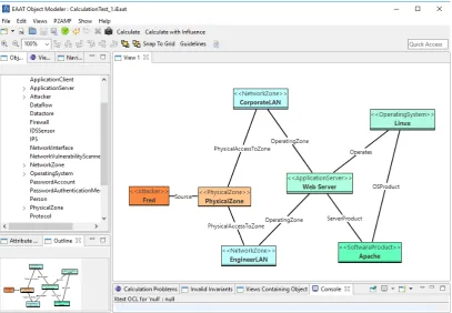
are able to exhibit probabilistic behaviour. The class modeller interface is shown in figure 2.2. The second part of EAAT is theObject Modeller, which is used to graphically model and define
instancesof previously createdClass Models. It provides an interface for the invocation of the P2AMF analysis for the loaded object model. On completion, the results are displayed in the graphical interface. A screenshot of the interface is shown in figure 2.3. The CySeMoL manual[36], contains a full specification of the use cases of the class modeller and the object modeller. It also provides a complete overview of the analysis features, and how these are specified.
The class modeller allows the grouping of classes and their relations into templates. These templates can be used in the object modeller to quickly create multiple instances of the classes defined within the templates. This feature reduces the modelling complexity and allows the composition of functional units of a model within templates.
2.3.4
The CySeMoL threat model
The threat model of CySeMoL specifies how an attacker who is attacking a predefined network infrastructure can be simulated. The components involved in this threat model are defined using the
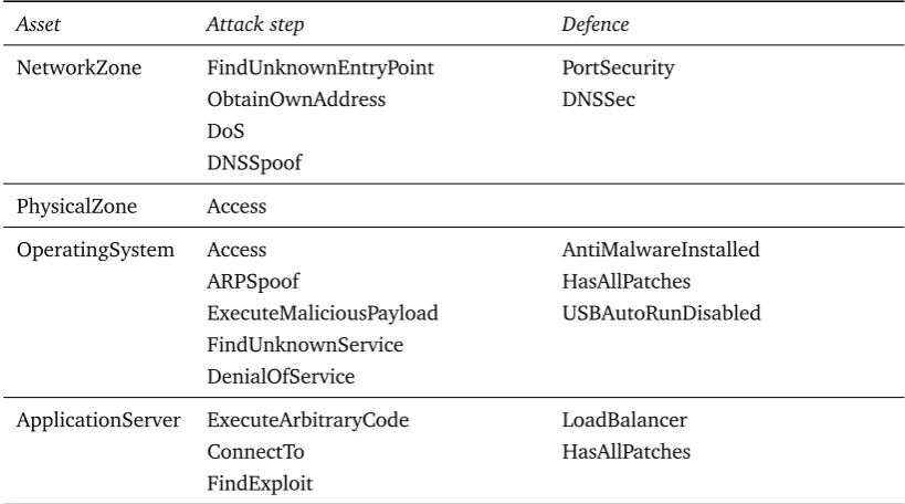
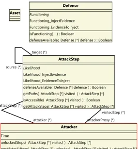
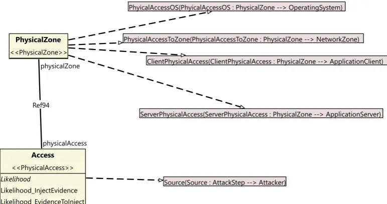
Class Modellerof EAAT. We list some components in table 2.1, for the other components, we refer to the CySeMoL papers, and the manual[35, 37, 36]. Within P2CySeMoL, there are four classes which play an important role in its analysis, these classes, which are also shown in figure 2.4, define the
Figure 2.2: A screenshot of the class modeller, in which a template is being edited.
Table 2.1: Non-exhaustive list of P2CySeMoL assets, and some of their associated attack steps and
defences.
Asset Attack step Defence
NetworkZone FindUnknownEntryPoint PortSecurity ObtainOwnAddress DNSSec DoS
DNSSpoof
PhysicalZone Access
OperatingSystem Access AntiMalwareInstalled ARPSpoof HasAllPatches ExecuteMaliciousPayload USBAutoRunDisabled FindUnknownService
DenialOfService
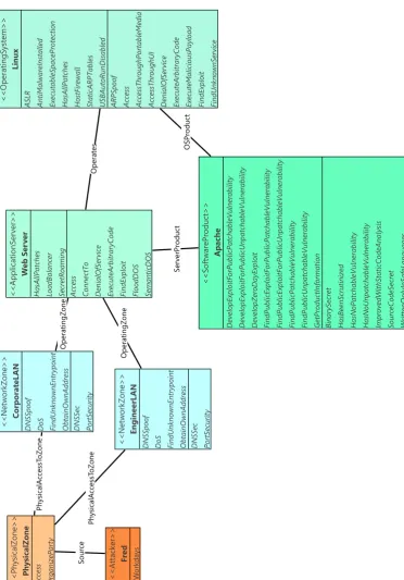
[image:16.595.92.502.504.732.2]Figure 2.3: A screenshot of the object modeller, in which a network infrastructure is being defined using templates (indicated by the guillemots). Note the available templates in on the left side of the interface.
The
Asset
class models components of the network infrastructure which can be attacked. Examples of such assets are servers, clients, and persons. For examples, see table 2.1 and the P2CySeMoL manual[36].The
AttackStep
class is used to model a specific attack, or a part of such an attack. Thesource
andtarget
relations are used to link attack steps to assets. An example of an attack step is theExecuteArbitraryCode
attack step, which is linked to theApplicationServer
asset. This attack step models the execution of arbitrary code on this server, and is a prerequisite for the execution of exploits on that server.The
Defence
class models countermeasures for attacks. Defences are modelled with a prob-abilisticisFunctioning
method, which allows to specify how the probability that a defence is functioning should be evaluated. For instance, a defence may perform better in the presence of other defences. The existence of these defence classes (which are connected to assets) is used in the deriva-tion code of attack steps to influence the success probability of those attack steps. For instance, if thePortSecurity
defense is enabled for theNetworkZone
asset, than theObtainOwnAddress
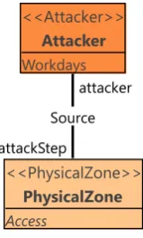
attack step will always fail.At the bottom of the diagram are the
Attacker
andAttackStep
classes, which model the potential actions the attacker can take. ThegetPaths()
operation of theAttackStep
class is used to determine the allowed sequences of attack steps. Whereas theisAccessible()
operation is used to determine whether theAttackStep
can be performed. The latter operation plays a double role by allowing more fine-grained restrictions on the sequence of attack steps, as well as determining the success likelihood of the attack.attacker (*) attackStep (*)
attackerProxy (*) visitedStep (*) source (*)
target (*)
Attacker
Time
unlockedSteps( AttackStep [*] visited ) : AttackStep [*]
nextAttackWave( AttackStep [*] unlocked , AttackStep [*] visited ) : AttackStep [*]
AttackStep
Likelihood
Likelihood_InjectEvidence Likelihood_EvidenceToInject
defenseAvailable( Defense [*] defense ) : Boolean getPaths( AttackStep [*] visited ) : AttackStep [*] isAccessible( AttackStep [*] visited ) : Boolean getAttackSteps( AttackStep [*] visited ) : AttackStep [*]
Asset
Defense
Functioning
Functioning_InjectEvidence Functioning_EvidenceToInject isFunctioning( ) : Boolean
[image:18.595.156.446.90.398.2]defenseAvailable( Defense [*] defense ) : Boolean
Figure 2.4: The root classes of P2CySeMoL.
In CySeMoL, the success of an attacker is modelled with respect to the time invested by the attacker. This allows the implementation of the notion that spending more time on an attack makes it more likely that it will succeed. One drawback of the CySeMoL implementation, is that the workdays parameter is defined as a constant which is the same for all attack steps. This design choice allows the analysis of CySeMoL to return a single probability of success, but makes it impossible to estimate the time-to-compromise of an asset.
2.3.5
Vulnerability Analysis
With the threat model in place, we will now examine how P2CySeMoL calculates the probabilities of success for an attacker. Recall that the method in which P2CySeMoL is defined, assumes a ‘workdays’ parameter, which indicates the amount of time an attacker spends on each individual attack step. Using this variable as its input, CySeMoL invokes P2AMF to estimate the success probabilities of the attacker.
When starting the analysis, P2CySeMoL first instantiates all probability distributions for the given
amount of workdays into a single probability[35]. For example, consider the following instantiation of a cumulative exponential distribution:
P(success,w) =1−e−0.2w λ=0.2
P(success,w=5)≈0.632
Next, the model is sampled according to the procedure described in section 2.3.7, however, we will go into more detail on how the OCL program is evaluated. For each sample, each with its own version of the P2AMF code due to the sampling of all probabilistic elements, CySeMoL determines the attack steps which are reachable by the attacker within the context of that sample.
P2CySeMoL searches for reachable attack steps by invoking the recursive
Attacker.nextAttackWave
operation. This operation recursively searches through a graph of attack step sequences. For a given set of reached attack steps V, the operation first determines the frontier setF: the set of attack steps reachable fromV, which are not already inV. The reachability relation is implemented through theAttackStep.getPaths
operation, which returns a set of attack steps reachable from that attack step. For each attack step inF, theAttackStep.isAccessible
method is evaluated to test whether that attack step is reachable. The accessible attack steps from the frontier set are added toV. More formally, letA be the set of accessible attack steps, thenV0=V ∪(F ∩ A).The
Attacker.nextAttackWave
operation is recursively invoked, until a fixed pointC is reached, in which no new attack steps are reachable. This setC contains all attack steps which are reachable by the attacker for the sample. Ultimately, the setC of reachable attack steps is determined for every sample. Next, these sets are aggregated to obtain an overall success probability for each individual attack step in the model. The success probability for a single attack step is determined by the amount of samples in which that attack step was reachable.2.3.6
Monte Carlo methods
We will introduce the details of how CySeMoL derives the required probabilities in the next section, however, this discussion requires some technical knowledge on Monte Carlo methods. Therefore, we will first describe what Monte Carlo methods are, and how they can be applied for the inference of probabilities.
Monte Carlo methods concern the drawing of many random samples from a system in order to obtain an estimate of its properties. The methods are often used to estimate properties of systems of high complexity[9]. The reason for this, is that by drawing samples, it is possible to quickly obtain a ballpark figure of the probability space. Using exact methods would require an exact inference of this space, which would be too complex. CySeMoL Monte Carlo methods by drawing samples from probability distributions to estimate the likelihood of success for attack steps.
Table 2.2: The probability distributions used in P2CySeMoL.
Parameters Meaning Definition Description
c∈[0, 1]⊂R Constant F(x) =c The Bernoulli ‘distribution’ λ∈R Rate F(x) =1−e−λx The cumulative Exponential
distribution.
µ,σ∈R Mean,
standard deviation
F(x) =p 1 2σ2πe
−(x2−σµ2)2 The Normal probability
den-sity function.
µ,σ∈R Mean,
standard deviation
F(x) =12+21erflogσpx−µ 2
The cumulative Log-normal distribution. Where the Gauss error function is denoted by erf(x).
α,β∈R>0 Shape, rate F(x) =γ(α ,βx)
Γ(α) The cumulative Gamma
distri-bution. WithΓ(x)the Gamma function, and γ(x,y) the in-complete gamma function.
Old versions of EAAT employed forward sampling, where every time a probability distribution was encountered, a sample was drawn from the corresponding distribution. An extension of forward sampling, which also supports the sampling of conditional probabilities is rejection sampling[85]. Rejection sampling is executed similar to forward sampling, with the difference that every sample which does not conform to the evidence is discarded. An advantage of this method is that its implementation is simple when forward sampling is already in place. A disadvantage is that in some cases, many samples might be discarded, which requires a large number of samples to be drawn.
With the introduction of P2AMF, EAAT switched its sampling method to the Metropolis-Hastings
algorithm[43]. The algorithm as popularized by Hastings[33, 9]is a Markov Chain Monte Carlo (MCMC) method, which generates new samples which depend on earlier samples. During this sampling, the underlying Markov Chain reaches a point where its stationary distribution nears the target distribution. This has the advantage that more samples conform to the desired distribution which reduces the amount of samples which need to be discarded when compared to rejection sampling. A disadvantage of the Metropolis-Hastings algorithm is that, because the underlying Markov Chain needs some time to reach its stationary distribution, someburn-insamples need to be drawn. These initial samples do not necessarily conform to the desired distribution, but instead reflect a transient state of the markov chain. Therefore, these burn-in samples need to be discarded.
2.3.7
P
2AMF
P2AMF[43], which stands for the ‘Predictive Probabilistic Architecture Modelling Framework’ is an
extension to the OCL language. The extensions include support for uncertainties in model variables and connections between classes. In addition, P2AMF inherits the support for collections, logic formulae and set operations from OCL. The uncertainties are specified using probability distributions, and P2AMF provides a method for performing inference on the resulting probabilistic models[43]. The supported probability distributions are listed in table 2.2. Additionally, P2AMF supports a linear approximation of a probability distributions, by providing it with a list of points from that distribution. These points are used to define a set of linear equations which model the probability density between those points. In section 2.3.5, we will examine a practical application of P2AMF when we explain how P2AMF is used to perform a vulnerability analysis of P2CySeMoL models. An
An analysis by P2AMF is conducted in the following way[35]: First, a user-specified amount
of versions of the model are instantiated. Next, for each version, all probabilistic expressions are sampled and evaluated. After this step, all probabilistic expressions have been cast into regular OCL expressions, which can be evaluated by the OCL parser. Finally, the results from each model instance are aggregated, and presented to the user in the graphical interface.
We will provide an example of the usage of P2AMF. Consider a coin with two sides which can
have different (positive) weights for each side. We say that the probability that the coin lands on a side is determined by the fraction of the total weight that side has. Ergo, we can calculate the probability that a coin with two sides which weighwheadsandwtailsgrams respectively in the following way:
P(Heads) = wheads
wheads+wtails
P(Tails) = wtails
wheads+wtails
Using P2AMF we can model this problem by defining a
Coin
class with two double-precision attributesweightHeads
andweightTails
, which denote the weight of each side. Next, we define aflipCoin
operation, which will flip this coin and return ‘true’ if the coin landed on the ‘Heads’ side of the coin. The derivation of this operation can be specified as follows, using P2AMF:1
let probability
:
Double
=
weightHeads
/
(weightHeads
+
weightTails)
in
2bernoulli(probability)
This code specifies the operation as a Bernoulli experiment, which results in either true or false, with probabilityP(Heads). P2AMF can be used to infer the probability of both ‘Heads’ and ‘Tails’. Even though this example is extremely trivial, we note that P2AMF supports the dependency of the weight of the coins on other classes. For example, we could model a minting machine, which outputs coins with different normally distributed weights for each side. This way, the
Coin
class can be reused in more complex models.2.3.8
Vulnerability analysis example
We will now explain the operation of P2AMF using an example network architecture defined
in CySeMoL. Our example concerns the CySeMoL object model shown in figure 2.6. In this model, we model an attacker ‘Fred’, who has successfully broken into a server room, reflected by the
PhysicalAccess
entry point in thePhysicalZone
instance. In this server room, it is possible to connect to two separate networks, modelled by the twoNetworkZone
template instances. From these networks, it is possible to connect to a web server, which runs Apache on an instance of the Linux operating system. This has been modelled by theApplicationServer
,OperatingSystem
andSoftwareProduct
instances. All template instances are left at their defaults, except for one network zone, theEngineerLAN
zone. For this network, we know that itsPortSecurity
defence has been disabled by the administrator. We model this by providing evidence thatEngineerLan.PortSecurity.functioning
is false. We will use the default value for the ‘workdays’ parameter of five work days per attack step.Returning to our example, we will now examine how the success probability of some example attack steps is determined by P2AMF. We will denote individual attack steps by their type, and will
enclose their target in parentheses. For example, the attack step
A
with targetT
will be denotedA(T)
. In our model, we have specified thePhysicalAccess
attack step as an entry point for the attacker. This will be our initial visited setV0. We will list this, and all other relevant sets from ourexample in table 2.3. Next, the frontier setF0is determined by evaluating the
getPaths
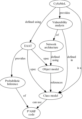
operationEAAT
Class model
spec Object model
spec
Probabilistic Inference
provides
P²AMF code
can use
references
of
CySeMoL
defined using
is a Vulnerability
analysis provides
defined in Network
architecture of
defined using
[image:22.595.155.444.130.550.2]Figure 2.5: An overview of the relations of the relevant CySeMoL-related concepts.
Table 2.3: The progression of the construction of the visited set in our example.
Set Contents
V0
PhysicalAccess(PhysicalZone)
F0
OrganizeParty(PhysicalZone)
,ObtainOwnAddress(EngineerLAN)
,ObtainOwnAddress(CorporateLAN)
.<<Attack er>> Fr ed W orkda ys <<PhysicalZone >> Physica lZone Access Organ izePa rty <<ApplicationServer>> W eb Ser ver HasAl lPa tches LoadB ala ncer SecretRoamin g
Access ConnectTo Denia
[image:23.595.111.484.130.664.2]lOfService ExecuteArb itr aryCode FindE xploi t FloodDOS Semanti cDOS <<Operating System>> Linux ASLR Anti Mal wareInsta lled Executab leSp aceProtecti on HasAl lPa tches HostFirewa ll Sta ticARP Tabl es USBA utoRun Disab led ARPS poof Access AccessThroughPortab leMedi a AccessThroughUI Denia lOfService ExecuteArb itr aryCode ExecuteMal iciousP ayloa d FindE xploi t FindUn knownServi ce <<SoftwareProdu ct>> Ap ache DevelopExp loit ForPub licPa tchabl eVuln erabi lity DevelopExp loit ForPub licUnp atchab leVul nerab ilit y DevelopZeroD ayExp loit FindP ubli cExpl oitForP ubli cPat chableVu lnerab ili ty FindP ubli cExpl oitForP ubli cUnpa tchabl eVulnera bil ity FindP ubli cPat chableVu lnerab ili ty FindP ubli cUnpa tchabl eVulnera bil ity GetProdu ctInformati on Bina rySecret HasBeenS crutin ized HasNoP atchab leVul nerab ili ty HasNoU npat chableV ulnera bil ity ImprovedWit hStat icCodeAna lysis SourceCodeSecret Writ tenOnly InSafeLan guag es <<NetworkZone>> Engin eerL AN DNS Spoof DoS FindUn knownEn tryp oint Obta inOwnA ddr ess DNS Sec PortS ecurity <<NetworkZone>> Corpor at eL AN DNS Spoof DoS FindUn knownEn tryp oint Obta inOwnA ddr ess DNS Sec PortS ecurity Source Physica lAccessT oZone Physica lAccessT oZone Operate s ServerProduc t Operatin gZone Operatin gZone OSProduc t
The first attack step fromF0is the
OrganiseParty(PhysicalZone)
attack step. This is anattack step we have introduced ourselves for testing purposes, and is not normally part of CySeMoL, it models the probability that an attacker who has access to a physical zone can attempt to organize a party in that area. CySeMoL evaluates the
isAccessible
operation of this attack step, in order to determine whether it should be added toV1.In the
isAccessible
operation of theOrganizeParty
attack step, we encounter a proba-bilistic distribution. The success probability of this particular attack step has been defined as being cumulativeGammadistributed with parametersα=0.014593 andβ=3630.152. We copied these parameters from a different attack step, and used this resulting distribution to test the ProbLog implementation of the Gamma distribution. Before starting the sampling process, this distribution has been converted to the evaluation of a single probability using the ‘workdays’ parameter. Since we use the default value of five workdays, the resulting success probability isF(x) = γ(α,βx)
Γ(α)
F(x) = γ(0.014593, 3630.152x)
Γ(0.014593) ≈0.91585
Analogous to this probability, the
OrganizeParty
attack step will be contained inV1in roughly91.6% of all samples.
The next attack steps are the
ObtainOwnAddress
attack steps for theCorporateLAN
andEngineerLAN
network zones. In the P2AMF code of theisAccessible
operation of this attackstep, we discover that this attack step is accessible when:
a)
PhysicalAccess(PhysicalZone)
∈ V.b) The
PortSecurity
defence is not operational.Item a) is already satisfied at this point. However, we have yet to determine whether the
PortSecurity
defence is operational for each network zone. Recall that we have defined evidence for thePortSecurity(EngineerLAN)
defence, as being disabled. This satisfies items a) and b) for theEngineerLAN
network zone, and thereforeObtainOwnAddress(EngineerLAN)
is added toV1. ThePortSecurity
defence has no implementation for itsisFunctioning
operation.In-stead, the default implementation is used, which states that the defence is functioning in 50% of all cases. Combining items a) and b) for the
CorporateLAN
network zone, we conclude that it will be added toV1in approximately 50% of all samples.Table 2.4: An overview of the model-driven-engineering languages and techniques discussed in sections 2.5 and 2.6.
Framework Modelling General-purpose Model-to-model Model-to-text
Eclipse Modelling Framework Ecore OCL ATL Xpand QVT
Eclipse Epsilon EOL ETL EGL
2.4
Model Driven Engineering
2.4.1
Introduction
In order to develop an extensible method for performing the vulnerability analysis of network infrastructures, we have developed models for the representation of these infrastructures, and for the definition of their components and how their vulnerability should be inferred. Such models have the potential to become quite large, for example a telephone carrier must be able to have a network infrastructure model in which each individual phone has to be modelled. Furthermore, we want to support the adaptation of our models, without requiring that our analysis methods have to be redesigned from scratch.
This type of problems also arise for software development, in which complex systems have to be developed which might require to be supported for over 20 years. An example of where the complexity of the long-term support of software is causing problems in practice, is the reliance of some financial institutions on legacy systems written in COBOL[26, 74], a programming language which is over 50 years old. With the need for new methods for the development of complex software, with a focus on the design instead on the implementation details, standards which are based on models rather than code have been developed. A well-known example of such a standard is UML, which is frequently used for the specification of software architectures.
Model Driven Engineering (MDE), is the practice of employing models as a first-class entity in the software engineering process[73], as opposed to computer programs. Due to the emergence of methods for code-generation, and modelling standards (for instance UML[27]and XML[70]), it is currently possible to use models for purposes other than for just the visualization of software design. Techniques from MDE involve the transformation of models into other models and code generation. For our purposes, we use the MDE techniques of modelling, code generation, model-to-model transformations, and model-to-text transformations. In this section, we will discuss the relevant aspects of these techniques, and will also go into detail on the concrete implementations of the techniques which we use. For this research, we use two frameworks with implementations of the techniques described below. In table 2.4 we provide an overview of the used model driven engineering tasks, and their respective implementations. For an overview of meaning of the abbreviations, we recommend section 1.7.
2.4.2
Modelling
Node label : EString
Graph
Edge label : EString
[1..1] target
[0..*] connections [0..*] nodes
Figure 2.7: An (Ecore) model for representing directed multi-graphs.
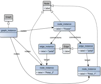
For software development applications, developers need only focus on the last two layers of modelling: the model and its instances. Consider the model as shown in figure 2.7, which is a definition (represented using UML) of a model designed for representing directed multi-graphs. This representation is defined using the Ecore metamodel from EMF. Figure 2.8 shows an instance of the model, where the UML inheritance arrows indicate which class the instances correspond to. All instances have their own values for the attributes defined in the model. Finally, figure 2.9 shows what the defined graph would look like. One way to obtain such a visual representation, is to transform the graph model instance to the Graphviz[22]format, and use the
dot
tool to generate the graph image.2.4.3
Model-to-model transformation
One of the concepts which give rise to practical flexibility of MDE, is the concept of model trans-formation. Model-to-model transformation is the act of taking one or more input models, and transforming these models to one or more output models in a structured way.
Transformations are often described as being either horizontal or vertical. A horizontal trans-formation uses the same source and target metamodel. Vertical transtrans-formations transform source models to a target model with a different metamodel. Consider a model for a program written in C. Performing a method-inlining optimization can be understood as transforming the C-program to a different C-program. This is an example of a horizontal transformation. Compiling the C-program to assembly code is an example of a vertical transformation.
Model transformations are applied to translate between multiple layers of abstraction[52]. Consider a social network application, where we model users who are connected to other users. We could directly model the connection graph of the users, however, it makes more sense to add one layer of abstraction, and use two models. One model for representing the users, and another for the graphs (for instance, the model we defined in figure 2.7). Using model transformations, we are able to achieve a ‘separation of concerns’, where the users model does not need to take any intricacies of potential target models into account.
Figure 2.8: An instance of the graph model of figure 2.7, with three nodes, and two edges.
The model transformations themselves are often specified using specialized model transformation languages, such as QVT[52], ATL[44]and ETL[49]. These transformations languages are either ‘declarative’, ‘imperative’, or a mixture of the two. In declarative transformation languages, the transformations are specified using rules. These rules in turn specify how to transform some element from the source language to the target language. The order of applying the transformation rules is determined by the transformation engine. Imperative languages explicitly specify the order of transformations, they advocate a more procedural style of programming. In practice, features from both declarative and imperative languages have their own strengths and weaknesses for practical transformations[49]. Therefore, there are also languages which support a mixture of declarative and imperative transformation specifications.
2.4.4
Model-to-text transformation
In addition to model-to-model transformations, a special type of transformation are those which generate text output. From an abstract perspective, we can consider text output as simply another type of model. However, because there are special tools for this class of transformations, we will discuss this kind of transformation in more detail. Furthermore, we have implemented some of our transformations as a model-to-text transformation (see section 4.5.4).
Using model-to-text transformation, it is possible to transform models to programs and other structured text. Examples of potential target formats are XML, JSON, HTML, C, Java, LATEX, SVG,
Flower
Petal_1 petal
[image:28.595.207.396.268.403.2]Petal_2 petal
Figure 2.9: The graph as defined by figure 2.8.
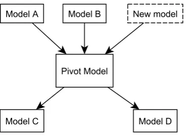
Figure 2.10: Demonstration of apivotmodel. Instead of having to create new transformations for the new model, only one new transformation needs to be defined. The gains rapidly increase when more models are added.
The concrete model-to-text transformation is defined usingtemplates. Examples of some com-mon template languages are Xpand[18]and the Epsilon Generation Language (EGL)[69]. These languages contain specialized constructs to separate text generation from procedural code. For instance, Xpand treats any tokens not inside guillemot signs (‘«’ and ‘»’) as text which is to be generated. Another common features of template languages are aggregate operations over model types, which allow the definition of operations for all objects of some type. This has the potential to reduce the amount of code required to specify text generation over types which occur in different contexts. For our work, we have used EGL, which we will discuss in more detail in section 2.6. Its application for our work is discussed in sections 4.5.2 and 4.5.3.
1
context Person
2
inv validAge
:
self
.
age
>= 18
Listing 2.1: An example of a simple OCL constraint.
1
context Person
::
befriend(stranger
:
Person)
:
Void
2pre
:
not self
.
nemeses
->
contains(stranger)
3
post
:
self
.
buddies
->
contains(stranger)
Listing 2.2: An example definition of a method, with pre- and postconditions. In the example, we define a
befriend
method, which takes another person as an argument. The operation may only be executed when the argument is not in the list of nemeses (we assume that such a list exists) of the current context. When the operation completes, we require that the buddies list contains the person which was passed as the argument to the operation.2.5
The Eclipse Modelling Framework
2.5.1
Introduction
The Eclipse Modelling Framework is a popular collection of open-source MDE tools[76]. It provides facilities for the definition and execution of models, model transformations, (custom) domain specific languages, and code generation.
The central part for modelling using EMF is theEcoremetamodel. It is defined in terms of itself, and is used as the metamodel for all EMF other models. It is inspired by the MOF (Meta-Object Facility) standard from the Object Management Group. To integrate with arbitrary EMF facilities and tools, it suffices to support the Ecore metamodel. EMF provides two built-in model editors for Ecore models, based on Eclipse. The first editor, theEcore model editor, provides a view of the tree structure of the model elements, and supports the specification of all Ecore features, according to the Ecore metamodel. The second editor, thediagram editor, features a UML-like interface for specifying views for Ecore models. In addition, it supports the creation of most features from Ecore models. Diagrams are stored in
aird
files, which are coupled with the Ecore model. This separate coupling (as opposed to storing the diagrams in the Ecore file, if that would be possible) enables multiple diagrams to be created to allow for multiple different views of Ecore models.2.5.2
Model invariants
In some cases, we want to restrict the amount of valid models, based on the values stored within those models. For instance, if we have a class
Person
who has a fieldAge
, we might want to require that its value is always greater than zero. This is an example of a model which contains invariants. For the specification of invariants on models, EMF provides the Object Constraint Language (OCL). Using the OCLinEcore technology, these constraints can be embedded into Ecore models. OCL constraints are specified for a context, usually an instance of a class. The aforementioned invariant can be specified as shown in listing 2.1.1
<?xml version="1.0" encoding="ASCII"?>
2<nl.utwente.fmt.pvai:PVAIContainer
3
xmi:version=
"2.0"
4
xmlns:xmi=
"http://www.omg.org/XMI"
5
xmlns:xsi=
"http://www.w3.org/2001/XMLSchema-instance"
6
xmlns:nl.utwente.fmt.pvai=
"http://nl/utwente/fmt/pvai"
>
7
<attacker
name=
"Fred"
></attacker>
8</nl.utwente.fmt.pvai:PVAIContainer>
Listing 2.3: An example of a XMI serialization of a PVAI model, containing a single instance of the Attacker class, for which the name field has been set to ‘Fred’.
2.5.3
Model transformation languages
For model transformation purposes, EMF provides facilities for the specification and execution of model-to-model transformations for the QVT and ATL languages. QVT is a set of model-to-model transformation languages aimed at transforming MOF models into other MOF models. The difference between imperative and declarative transformations as mentioned in section 2.4.3 is also observed in the QVT languages. QVT provides a unidirectional imperative transformation language, as well as a bidirectional declarative language.
ATL is a declarative model transformation language, which supports the transformation of a set of input models to a set of output models. Its programs define transformation rules, where the transformation engine determines a suitable transformation order for objects. The language distinguishes non-essential operations from transformation operations through the support for ‘helper’ functions. These functions provide a better separation between transformation code and calculations.
2.5.4
Serialization
XMI, which stands for XML Metadata Interchange[31], is a serialization format for MOF models based on XML. It is commonly used as a encapsulation vehicle for passing models between transformation steps in transformation workflows, and for storing model instances on a filesystem. Being based on XML, it is also used for transferring model data using web services[23]. EMF contains an implementation of XMI for the serialization and deserialization of Ecore models.
An example of a XMI serialization of our PVAI model (see section 3.3) is shown in listing 2.3. In the first line of this example, we have the XML identification line which provides an indication that the XML format is used, and contains some metadata which might be relevant to XML parsers. The next tag denotes the existence of an instance of the
PVAIContainer
class. Lines 3 until 5 provide some metadata which describe the version and schema of the XMI implementation which was used. In line 6, the namespace of the metamodel which is used is stored, which is used by the XMI reader to reconstruct the model objects stored in an XMI file. Nested within thePVAIContainer
tag is anattacker
tag, which specifies an instance which is contained in the2.6
Eclipse Epsilon
2.6.1
Introduction
In addition to the languages provided by EMF, Eclipse Epsilon is another framework for MDE tasks. For our model-driven engineering goals, we will use the technologies and languages provided by this framework. The goal of Eclipse Epsilon is to provide accessible and flexible task-oriented languages for a wide range of model-driven engineering purposes.
The framework is centred around a newly defined general purpose language, the Epsilon Object Language (EOL)[47, 48]. Using this language, it is possible to create, read and modify models. The Eclipse Epsilon framework provides an execution engine for EOL, which runs on the Java Virtual Machine. The Epsilon Object Language is designed in such a way that most of the OCL syntax is also valid EOL syntax.
Eclipse Epsilon is able to interact with multiple model technologies, among which EMF and XML. This is implemented through the Epsilon Model Connectivity (EMC) layer[47]. This layer provides an abstraction to hierarchical models, and provides general operations such as the addition and removal of classes, and the definition of inheritance. Models are loaded in read-only, write-only or read/write mode, after which all other Epsilon tools are able to refer to the loaded models. The Epsilon framework provides EMC implementations for models and metamodels stored using the Ecore, XML and XMI formats. These implementations enable the tools from the Epsilon framework to be used on EMF models.
2.6.2
The Epsilon Object Language
The Epsilon Object Language (EOL) is general-purpose programming language, which is used as the base for all other languages from the Epsilon family. An important feature provided by EOL is the ability toimportcode from other scripts, which greatly enhances the portability and reusability of EOL scripts. EOL supports the iteration constructs often found in imperative languages, specifically while loops, if-then-else and switch constructs, and collection iteration. Similar to the helper functions from ATL, EOL introduces user-defined operations, which may be invoked in other code. In order to quickly optimize expensive operations, EOL has a caching annotation, which causes the engine to cache values for that operation.
The execution engine of EOL uses adynamic dispatchmechanism[47]. This means that when an overloaded method is called, the concrete method which will be invoked is determined during runtime, based on the runtime types of its arguments. A similar dispatch mechanism is used by the Groovy[77]and JavaScript languages, whereas Java implements a limited form of dispatch using virtual methods. Nevertheless, EOL is able to import and usenative Javaclasses when they are available on the classpath of the execution engine. Other execution related features of EOL are the support for exceptions and transactions. This allows scripts to gracefully handle potential errors during execution.
2.6.3
The Epsilon Transformation Language
We will now dive deeper into the task oriented languages themselves. The first task-oriented language which we will discuss is the ETL language, the Epsilon Transformation Language, which is oriented at the specification and execution of model-to-model transformations. The ETL language extends EOL by introducing additional language features on top of the specification described in section 2.6.2. Being a part of the Epsilon ecosystem, ETL is able to use the Epsilon Model Connectivity Layer to support transformations from multiple input models to multiple output models[47].
From a programming perspective, the language is designed as a ‘hybrid’ transformation language by supporting features from both the imperative and declarative styles of model transformation programming. ETL introduces transformation rules which can be invoked to transform a source entity to a number of target entities. On the other side of the spectrum, ETL allows to define a complete model-to-model transformation using imperative EOL operations.
As mentioned, ETL introduces the concept of transformation rules. These language construct define a (unidirectional) mapping from a single instance from one of the source models to one or more instances from the target models. When the ETL execution engine is invoked on an ETL program, normal rules are applied to all instances of the source type. The result of which is the generation of new instances for the target models. Instead of transforming all instances, it is possible to filter the selection of source instances by defining guards for the transformation rules. These guards are defined as boolean functions over the input instance, which determines whether that instance is applicable for transformation by the rule for which the guard is defined.
It is also possible to obtain the resulting objects from the transformations during the transforma-tion by invoking the special
equivalent
orequivalents
functions on instances from the source model. Whenever possible, the ETL engine will obtain the transformed instance for the source instance, which can then be accessed from the code which requested the transformation. Related to this feature is that ETL supports so-called ‘lazy’ rules (a concept borrowed from ATL[45, 47]), which are transformations which are not applied automatically, but only so when they are explicitly requested by invocation of one of theequivalents
functions.Finally, ETL supports inheritance of rules to facilitate the transformation of hierarchical class structures. A child rule which extends another parent rule first applies the transformation defined in the parent rule, after which the child rule is executed, which obtains access to the transformation result from the parent rule.
2.6.4
The Epsilon Generation Language
Another language from the Epsilon family which we use in our research is the Epsilon Generation Language, or EGL. This language, which extends the EOL language (see section 2.6.2), is oriented at model-to-text transformation, and is a template-based code generator[47]. Programs in EGL use special separator tags (‘
[%
’ and ‘%]
’) to distinguish between the dynamic and static parts of the program. The static parts are directly exported to the output of the program, whereas the dynamic parts are evaluated, and are able to alter their text output.Within the dynamic parts, it is possible to use any features from the EOL language, including the definition of new functions. The dynamic code has access to the special
![Figure 2.1: An overview of the concepts which arise in the discussion of threat modelling, as definedin ISO/IEC 15408-1:2009[39].](https://thumb-us.123doks.com/thumbv2/123dok_us/9780197.479105/13.595.133.462.126.361/figure-overview-concepts-arise-discussion-threat-modelling-denedin.webp)