Desi
gn
f
or
vacuum
syst
ems
I
nt
er
nshi
p
r
epor
t
Mast
er
Mechani
cal
Engi
neer
i
ng
Desi
gn
Engi
neer
i
ng
2
This report to finalize the internship at CTI for the master study mechanical engineering at the University of Twente
Design for vacuum systems
Master Mechanical Engineering Universiteit Twente
Postbus 217 7500 AE Enschede the Netherlands
Centro de Tecnologia da Informação Renato Archer Rua Dom Pedro I, Km 143.6
Campinas, SP Brazil
First company supervisor S.Q. Bezerra, BSc.
Secondary company supervisor V. Pimentel, BSc.
Supervisor University of Twente dr. ir. W.W. Wits
Tijmen van Diepen S1015249
Data of publication 21/06/2015
Editions 1
Pages 64
3
Preface
Enschede May 2015
This report is the result of my internship assignment at CTI in Brasil. I want to thank CTI for providing the assignment. And I especially want to thank Stefany Bezerra and Vinicius Pimentel for helping me. Also a thank you for the DINF (Igor and Jonnas) and D3D (Aline and Marcelo) departments, for manufacturing various components and prototypes.
The internship and my time in Brazil was amazing. I never imagined myself living for four months in another continent. But I would recommend to all who are thinking about it.
CTI, obrigado!
Tijmen
4
Abstract
The assignment described in this report is executed for Centro de Tecnologia da Informação Renato Archer. A government based research facility situated in Campinas, Brazil. Several of the research programs conducted there, involve the use of advance vacuum systems. To improve the research possibilities with these systems, additional equipment is necessary.
Therefore the assignment is the redesign of three pieces of equipment that are used in vacuum systems. A rotary feedthrough for a planetary system. And a sample introduction system and a sample holding system for a double chamber vacuum system.
In the first part of this report a feedthrough to optimize evaporation decomposition is designed. To create a film with a more uniform thickness, CTI recently designed a planetary system. However this system lacks a driving principle. This is the assignment for part 1. The first step in completing this assignment is analysing the system and its restrictions. The resulting main requirements are that the system should be manufacturable at the workshop of CTI, and only be made of materials that are in stock at CTI. Furthermore the system should not reduce the quality of the vacuum in which the experiments are conducted.
The second step is to create two concepts, using the input from the analysis. The first concept is based on magnetic decoupling to drive the shaft of the planetary system. In the second concept the actuator directly drives the shaft. This requires a dynamic seal, in the form of a rotary feedthrough. Based on the requirements the first concept is selected to be further developed. The result is a final design which is ready to be manufactured in the workshop. This has not been done yet during the writing of this report. So the final result is not available, and cannot be tested and evaluated.
In the second part, two systems are designed to improve experiments on measuring the work function of a surface of a material. At CTI, the work function is currently measured in a small vacuum chamber. Due to the size and because it is a single chamber vacuum system, the results are not reliable. To improve the results CTI procures a double chamber vacuum system. To make the system confirm with the technical necessities and to decrease the costs, two parts of the feedthrough are designed and manufactured at CTI. These are the sample introduction system and the sample holding system. The designing of both systems is the assignment of part 2. To create both designs firstly an extensive analysis of the situation and of the restrictions of both systems is executed. This resulted into two programs of requirements (one for each system). The most important requirements are: the sample must never drop, the systems are manufacturable by the workshop of CTI, and the friction between parts made of the same materials should be reduced as much as possible.
Secondly several ideas for the sample introduction system are created, of which two are selected and developed into a concept. Both concepts involve a rotating movement to grab and release the sample. And both concepts are optimized to reduce interference with the experiments. Finally one concept is chosen based on the requirements. The final design involves a lever movement to grab and release the sample. And a spring is used to prevent dropping the sample.
Thirdly the sample holding system is designed. CTI already created an idea for the system. This idea further developed into a final design. In this design the shape of the holding system is optimized for easy manufacturing and for reduction of interference with the experiments. Lastly the sample holder is able to guide the introduction system.
5
Contents
1 Introduction ... 7
2 Centro de Tecnologia da Informação Renato Archer ... 8
2.1 Centro de Tecnologia da Informação Renato Archer ...8
2.2 Divisão de Mostradores de Informação ...8
2.3 Students at CTI ...8
2.4 Conclusion ...9
Part 1
3 Analysis ... 113.1 Evaporation and deposition under vacuum ...11
3.2 Problem statement ...12
3.3 Solution ...12
3.4 Conclusion ...12
4 Assignment ... 13
4.1 Assignment ...13
4.2 Analysis ...13
4.3 Program of requirements ...13
4.4 Conclusion ...14
5 Concepts ... 15
5.1 Concept 1 ...15
5.2 Concept 2 ...16
5.3 Concept choice ...17
5.4 Conclusion ...17
6 Detailed design ... 18
6.1 Final Design ...18
6.2 Assemblies ...18
6.3 Method of production ...23
6.4 Conclusion ...24
7 Conclusion ... 25
6
Part 2
8 Assignment ... 27
8.1 Work function ...27
8.2 Current situation...27
8.3 Problem ...29
8.4 Conclusion ...29
9 Analysis ... 30
9.1 Vacuum ...30
9.2 Existing parts ...30
9.3 Market analyses ...31
9.4 Assignment ...33
9.5 Program of requirements ...34
9.6 Conclusion ...34
10 Sample introduction system ... 35
10.1 Idea generation ...35
10.2 Idea selection ...39
10.3 Concepts ...41
10.4 Concept selection ...45
10.5 Conclusion ...46
11 Sample holding system ... 47
11.1 Idea ...47
11.2 Concept ...48
11.3 Conclusion ...49
12 Detailed Design ... 50
12.1 Sample holding system ...50
12.2 Sample introduction system ...51
12.3 Manufacturability ...55
12.4 Conclusion ...56
13 Conclusion ... 58
13.1 Recommendations ...58
14 Conclusion ... 59
14.1 Recommendations ...59
15 Process evaluation ... 60
15.1 University of Twente...60
7
1
Introduction
This report is the result of an assignment conducted for an internship at Centro de Tecnologia da Informação Renato Archer (CTI). The internship is part of the master study Mechanical Engineering at the University of Twente. The purpose of the internship is to gain experience on working in the industry and specifically in this case to gain experience in working abroad.
The schema below shows the structure of the total assignment. Firstly a preliminary research about CTI is conducted. The reason for this is to get a good understanding of both the working environment, and the opportunities and constraints of the company. Hereafter the total assignment is separated in two different parts.
In the first part a feedthrough for a planetary system in an evaporation deposition machine is designed. In the current evaporation deposition system at CTI samples are placed on a static holder. Using this method the resulting film deviates in thickness. To decrease the deviation Glenn Roozing (a previous student from the University of Twente at CTI) designed a planetary system. This system is almost finished; however a feedthrough to drive the system has to be designed. This has been done in collaboration with Glenn Roozing in the first part of the assignment.
The second part is an individual assignment on a system that can measure the work function. Currently CTI has to use a small vacuum chamber measure it. To increase the quality of the measurements, CTI will procure a dual chamber vacuum system. To conduct the experiments in this type of system, a sample has to be transferred from the introduction vacuum chamber to the main vacuum chamber. The assignment is firstly to design a linear feedthrough system that can transfer the sample, the so called sample introduction system. And secondly a holding system that can hold the sample in the main chamber, the sample holding system. Finally both systems are optimized and made sure that they are compatible with each other.
8
2
Centro de Tecnologia da Informação Renato Archer
This chapter analyses the company CTI to get an insight in the possibilities and constraints of executing a design assignment. This is done by firstly discussing CTI self in section 2.1. In section 2.2 DMI, the division of CTI that provided the assignment and where the assignment is executed, is discussed. Finally a close look at the role of students at DMI is taken in section 2.3.
2.1
Centro de Tecnologia da Informação Renato Archer
CTI is a research and development centre located at Campinas in the state of São Paulo in Brazil. The translation of the name is “Centre of Information Technology Renato Archer1”. The research areas of
CTI are: information technology, (micro) electronics, displays, software, and automation (CTI, 2015). Being a research unit of the Ministry of Science, Technology and Innovation (MCTI), CTI is a government funded research centre. This means that they have to justify all their expenses to the ministry. The goal of CTI is to develop new innovations and technologies and to transfer those to the industry of Brazil.
2.2
Divisão de Mostradores de Informação
The division that provided the assignments is Divisão de Mostradores de Informação (DMI). Translated to English, “Division of Display Information”, which is also the main research topic of DMI. Examples of research projects are among others; developing new types of displays and solar cells, researching organic electronics, developing new processes for nanotechnologies (CTI, 2015). The assignments of this report mainly contributes to research using nanotechnology in displays, but are also useful for other researches, conducted both at DMI and CTI.
2.3
Students at CTI
To be able to conduct new and innovative research on displays, specialized and state of the art equipment is required. However, CTI is funded by the government and therefore the budget to procure new equipment is strict. Also designing the equipment themselves is limited, due to the lack of employees that have experience with design.
To solve this problem, students of the University of Twente in the Netherlands are invited to aid in developing new equipment.2 During the design process the students have to take the previously
mentioned strict budget into account. This means that only available workshop equipment and available materials can be used. To ensure this, frequent corresponding with the workshop is necessary.
To aid the student in their process, two sources of information can be consulted. Firstly the staff that uses the new equipment. Even though the staff is not experienced with designing new equipment, the staff has lots of experience using similar equipment. So their findings should be taken into account during the design process.
Secondly, CTI has its own workshop where the new equipment will be manufactured. The equipment at the workshop is capable of processing different types of materials, from stainless steel up to tungsten. There are also several 3D-printing machines available at a special division dedicated to rapid prototyping. The workers of both workshops have years of experience and knowledge about what is possible to manufacture, and what not. This knowledge and the limitations of the available equipment should be taken into account during the design process.
9
2.4
Conclusion
10
Part 1
Part 1 describes the process of designing a feedthrough for a planetary system in an evaporation deposition machine. This assignment is executed in collaboration with Glenn Roozing (a student at CTI form the University of Twente) and is a continuation of his work on the planetary system.
The first step in designing the feedthrough is an analysis of the work Glenn Roozing has executed (Roozing, 2014). This will provide an understanding of the underlying reasons for this project. The result of this analysis is described in chapter 3. The actual problem will be explained in detail chapter 4. This includes an analysis of the situation, the constraints of the design process, and the resulting program of requirements. In chapter 5 two concepts are created, and a choice for one concept is made. The chosen concept is developed in chapter 6. Finally the conclusions and recommendations of part 1 can be found in chapter 7.
11
Eq. 1
3
Analysis
This chapter discusses the assignment that Glenn Roozing has executed at CTI. The result of his assignment is the input for the design process of the feedthrough system. In this chapter section 3.1 describes the motivation for his assignment. This is done by explaining the process of evaporation and deposition. Hereafter the problem that CTI has during evaporation and deposition in the current situation, is described in section 3.2. The results of Glenn Roozing will be shortly discussed in section 3.3.
3.1
Evaporation and deposition under vacuum
Evaporation and deposition is a method to create a very thin film (about hundrednanometer) of a certain material. The thin film can be used for a lot of different research projects, but at it is mainly used for research with microelectronics.
Principle of evaporation and deposition
Evaporation and deposition is executed in the following four steps. The first step is placing the material that needs to be evaporated on a crucible. The second step is placing the crucible in a vacuum chamber, and hanging a substrate above the crucible. The third step is closing the vacuum chamber, and creating a medium to high vacuum. Hereafter the material is heated and starts to evaporate. The evaporated particles will rise up until it meets the substrate. There the particles will condensate, because the substrate is considerably cooler. The condensation of the particles is the actual creation of the thin layer. Finally the chamber is opened, and the thin layered film can be retrieved.
Reasons to use a vacuum
Evaporation and deposition is executed in a vacuum chamber for several reasons. Firstly and most importantly is that a vacuum allows the particles to travel directly to the substrate, without colliding into other particles which would contaminate the experiments3. This means that when increasing the
vacuum, the resulting thin film will increase in quality. Secondly materials evaporates at a lower temperature in a vacuum. So the experiments can be conducted in a more controlled environment.
Uniform film thickness
As mentioned CTI uses the thin films for microelectronics. One of the main requirements for materials to be used in microelectronics is a uniform resistance over the whole film. The resistance of a material is determined by:
𝑅 = 𝜌 ∗𝑙 𝐴
Equation 1 shows that the resistance changes when the thickness of a material changes. So to get a uniform resistance, a uniform thickness is required. How this can be accomplished will be discussed in the next part.
12
3.2
Problem statement
To execute evaporation deposition, CTI currently uses the vacuum chamber EV400 (found in appendix 1) and a static holder for the substrate. Because the holder is static, the resulting films have a non-uniform thickness. To explain why, the material that is evaporated should be regarded as a point source and the substrate a surface. During deposition most of the evaporated materials will concentrate in the centre of the surface. And the layer decreases gradually in thickness going to the outside of the substrate.
3.3
Solution
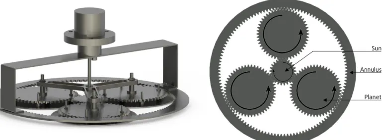
The assignment of Glenn Roozing was to create a holder for the substrate that enables the creation of a film with a more uniform thickness. And it had to be used in the current EV400 vacuum chamber. The solution is the planetary system in figure 1. The planetary system consist out of a sun, three planets (that holds the substrates), and an annulus. The latter one is stationary, while the first two can rotate. The input of the system is the sun, which will rotate around its own axes. This movement causes the planets to rotate around their own axes. And at the same time rotate around the sun, within the annulus.
By placing a substrate on a planet, the substrates rotates around two axes during evaporation and decomposition. This movement will decrease the uniformity variation from about 80% to 2%. (Roozing, 2014). An additional advantage is that the planetary systems can hold three substrates with a diameter of 120mm. Compared to the old holder that could contain one substrate with a diameter of 150mm.
3.4
Conclusion
To be able to use thin films in microelectronics, the film has to have a uniform thickness. The films created by the current evaporation and decomposition system of CTI have a too large uniformity variation. Therefore Glenn Roozing designed a planetary system which allows rotation of the substrates around two axes. This has increased the uniformity substantially.
13
4
Assignment
In this chapter the assignment part 1 is discussed and analysed is respectively section 4.1 and 4.2. The result is a program of requirements which can be found in section 4.3.
4.1
Assignment
The planetary system as created by Glenn Roozing is approved by CTI and is ready for production. However, one part of the system still has to be designed. This is a system that drives the sun. This system cannot be placed inside the vacuum chamber, and the chamber should be closed at all times. Therefore a feedthrough that transfers the mechanical energy from outside to inside the vacuum chamber to inside the chamber has to be developed.
The assignment of this part is formulated as:
“Design a rotary feedthrough that can be manufactured by CTI, and is compatible with the planetary system and the EV400 vacuum chamber”.
4.2
Analysis
An extensive analysis has been executed, and the results are four elements that should be taken into account during the design process.
Firstly, the feedthrough should be developed in less than a month. The reason for this is that researchers at CTI require to use the system to execute evaporation and decomposition within one month of the starting date. This results that fast design choices have to be made and that the final product should be easy to manufacture.
Secondly, the costs of the system have to be as low as possible, as mentioned in the previous chapter. To accomplish this, only available parts can be used. These parts are:
An electric motor of 12V DC serial number F006WMO310
Four round magnets with a diameter of 10mm and a height of 5mm A block aluminium of 70x65x20mm
ISO Standard bolts and buts
Stainless steel sheet metal of 3mm thickness Stainless steel rods with a diameter of 10mm
Thirdly the new system should fit on top of the EV400. The chamber has a hole in the lid with a diameter of 35mm and three M5 thread holes. The vacuum chamber can be found in appendix 1. Lastly, there are only two types of seals that can be used for the feedthrough; a static and a dynamic seal. A static seal is used for fixed components. And a dynamic seal can be used for moving components. The fact that only these two type of seals are available, limit the possibilities of the design process.
4.3
Program of requirements
Based on the analysis, the following program of requirements is set up. Leaking should be reduced as much as possible
Constructed only of parts that are available at CTI Compatible with EV400 vacuum chamber
14
4.4
Conclusion
15
5
Concepts
This chapter discusses the development of two concepts in respectively section 5.1 and 5.2. Hereafter both concepts are analysed using the program of requirements in section 5.3.
Due to the strict requirements and development time, the concepts are not fully developed. Instead the two concepts are developed up to a level that a funded decision between the two can be made.
5.1
Concept 1
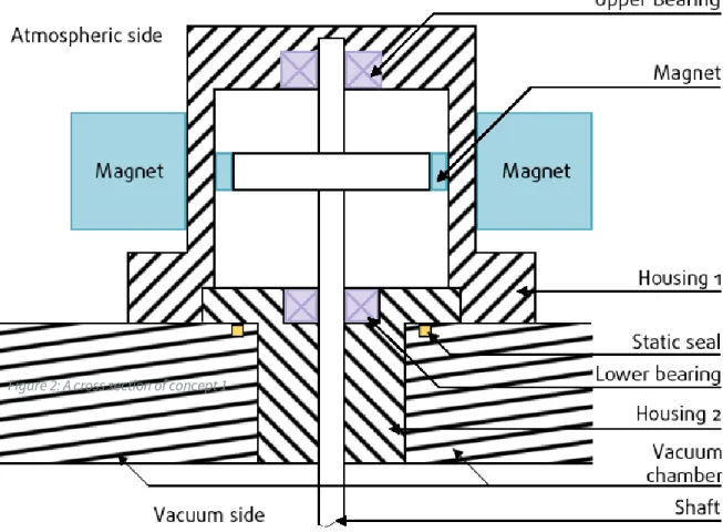
Concept 1 can be seen in figure 2, the displayed image is a cross section to provide an indication of the working principle. In this concept mechanical energy is transferred using magnetic coupling. Using this method the atmospheric side and the vacuum side are separated by a non-magnetic barrier. On the atmospheric side magnets rotate around the non-magnetic barrier. On the vacuum side a magnet is attached to a shaft. By rotating the atmospheric magnets the vacuum magnet will follow, resulting in a rotation of the shaft and thus the elliptic gearing. Because the inner shaft does not have a connection to the atmospheric side, a static seal can be used. The seal is placed between the non-magnetic barrier and the top of the vacuum system.
16
5.2
Concept 2
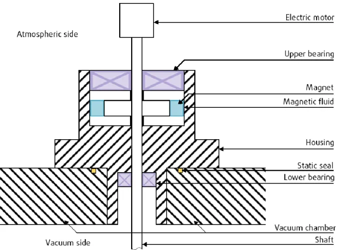
Concept 2 can be found in figure 3, again for clarification purposes a cross section is shown. In the second concept the mechanical energy is transferred directly from the motor to the shaft. This principle requires the use of a dynamic seal.
The dynamic seal used in this concept is a rotary feedthrough. This is a proven method in which de atmospheric and the vacuum side are separated by a magnetic fluid. Magnetic fluid, also called ferrofluid, is a liquid that becomes strongly magnetized in the presence of a magnetic field. In this concept the rotating of the shaft (at which permanent magnets are attached) provide the magnetic field. The created dynamic seal prevents leakage and the magnetic liquid reduces friction between the housing and the magnet (de Haas, 1976). This enables the direct transfer of mechanical energy to the shaft without reducing the vacuum.
17
5.3
Concept choice
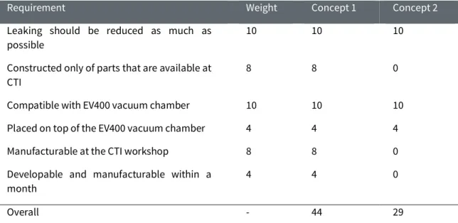
The concept choice between the two concepts, will be made using a Multi-Criteria Decision Matrix. The input for the matrix is the program of requirements. And the matrix is completed in correspondence with the persons from the workshop and with colleagues at DMI.
Table 1: The Multi-Criteria Decision Matrix for selecting a concept
Requirement Weight Concept 1 Concept 2
Leaking should be reduced as much as possible
10 10 10
Constructed only of parts that are available at CTI
8 8 0
Compatible with EV400 vacuum chamber 10 10 10
Placed on top of the EV400 vacuum chamber 4 4 4
Manufacturable at the CTI workshop 8 8 0
Developable and manufacturable within a month
4 4 0
Overall - 44 29
The Multi-Criteria Decision Matrix shows a significant difference in the score between the two concepts. The difference is explainable by the difference between the two concepts. Concept 1 uses a more difficult method to transfer the energy, but uses a simple static seal. While concept 2 uses a (simple) direct connection between the shaft and the actuator. But the required dynamic seal is hard to manufacture. Since the manufacturability is very important concept 1 has the preference to be further developed.
5.4
Conclusion
18
6
Detailed design
In this chapter the detailed design of the feedthrough is discussed. Firstly the final design and its working principle are explained in section 6.1. To provide understanding of the different components and their relations, the different assemblies are discussed in section 6.2. Finally the method of production will be discussed in section 6.3.
6.1
Final Design
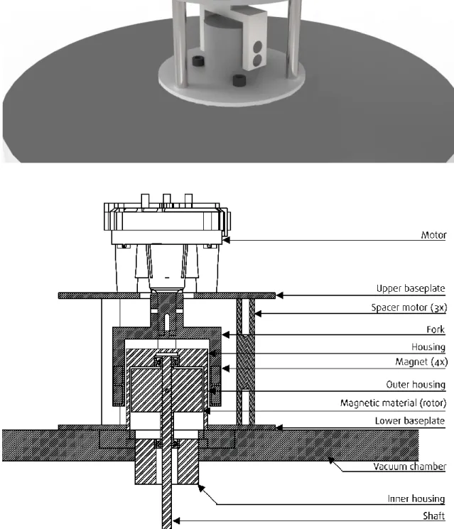
The final design can be seen in figure 4. Here the feedthrough is mounted on the lid of the EV400 vacuum chamber.
Working principle
The working principle of the final design will be discussed according to figure 4b. This figure shows a cross-section of the final design. As mentioned in section 5.1, the transfer of energy is based on magnetic coupling. To create a permanent magnetic field, four permanent magnets are placed inside a fork at the atmospheric side (the stator). They pull on the ferromagnetic material on the vacuum side (rotor). So by rotating the fork, the rotor will rotate and thus driving the planetary system. The method requires the rest of the components (housing, fork, baseplates, and spacer) to be made of a non-ferromagnetic material.
6.2
Assemblies
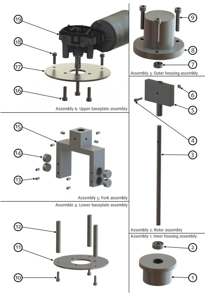
The feedthrough can be divided into six different sub-assemblies, which can be found in figure 5. These will be discussed separately by first listing the separate components, and secondly describing the purpose and details of the assembly.
1: Inner housing assembly
The inner housing assembly consists out of the following two components. Table 2: Bill of materials of the inner housing assemply
# Component name Component Description Quantity
1 feed through inner housing Inner piece feedthrough housing
1
2 ISO 15 RBB - 105 - 8,DE,AC,8 68 SKF 605ZZ bearing 1
19
20
2: Rotor assembly
The rotor assembly consists out of the following four components. Table 3: Bill of materials of the rotor assemply
# Component name Component Description Quantity
3 axis sun Shaft 1
4 ISO 4762 M2 x 10 - 10C Socket head cap screw M2 x 10 1
5 Rotor_magnetic Rotor inside feedthrough 1
6 Hexagon Thin Nut ISO - 4035 - M2 - C Hexagon Thin Nut M2 1
The rotor assembly fits in the inside the “feed through inner housing”. The “rotor magnetic” is connected to the shaft using a M2 screw and bolt.
3: Outer housing assembly
The outer housing assembly consists out of the following three components. Table 4: Bill of materials of the outer housing assemply
# Component name Component Description Quantity
7 ISO 15 RBB - 105 - 8,DE,AC,8 68 SKF 605ZZ bearing 1 8 feed through outer housing Outer piece feedthrough housing 1 9 ISO 4762 M6 x 30 - 30C Socket head cap screw M6 x 30 3
The “feed through outer housing” is mounted on top of the inner housing. The holes in the flange correspond with the existing holes in the lid of the vacuum chamber. This allows for easy manufacturing and assembly of the total system. The bearing is added to the assembly to support rotation of the shaft at the top.
4: Lower baseplate assembly
The lower baseplate assembly consists out of the following three components. Table 5: Bill of materials of lower baseplate assemply
# Component name Component Description Quantity
10 ISO 4762 M5 x 16 - 20C Socket head cap screw M5 x 16 3 11 sub frame base plate lower Sub frame base plate lower 1
12 spacers motor Spacers motor 3
21
The spacer are added to allow for rotation of the fork. The spacer are attached using socket head cap screw, and have to be attached to the “sub frame base plate lower” before mounting the assembly on the outer housing.
5: Fork assembly
The fork assembly consists out of the following three components. Table 6: Bill of materials of fork assemply
# Component name Component Description Quantity
13 ISO 4026 - M3 X 5 – C Socket set screw at point M3 x 5 8
14 Magnets Magnets 4
15 Fork Fork 1
The fork is designed so it fits around the outer housing and is at the same time small enough to rotate without touching the spacers. The fork contains four gaps for the four permanent magnets that create the magnetic field. By locking the magnets using socket screws, they can be easily removed when necessary. Increasing maintainability and ease of assembly. A similar system (for similar reasons) is used to attach the fork to the motor. To decrease the number of different components, the same size screws are used.
6: Upper baseplate assembly
The upper baseplate assembly consists out of the following four components. Table 7: Bill of materials of upper baseplate assemply
# Component name Component Description Quantity
16 ISO 4762 M5 x 16 - 16C Socket head cap screw M5 x 16 3 17 sub frame base plate upper Sub frame base plate upper 1 18 ISO 4762 M6 x 20 - 20C Socket head cap screw M6 x 20 3
19 F006WM0310 Motor Bosch F006WM0310 DC
24V
1
22
23
6.3
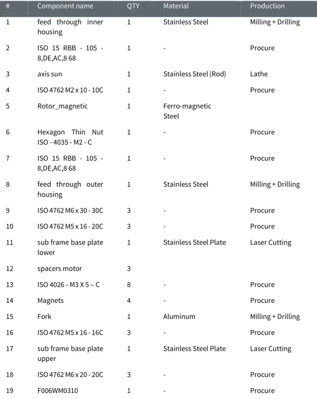
Method of production
In this section the material and the method of production of each component is discussed. The parts that are already available at CTI, like the motor, nuts, bolts, and bearings will not be discussed in this section. The production method of the rest, can be seen in table 8. As discussed in section 4.2 the available materials should be used as much as possible. To accomplish this, the table is set up in cooperation with the technicians of the workshop. And where necessary some components were slightly redesigned so they fit in the existing materials (this is already accounted for in the explanation of the components in the previous section).
Table 8: Overview of the components that will be manufactured or procured at CTI
# Component name QTY Material Production
1 feed through inner housing
1 Stainless Steel Milling + Drilling
2 ISO 15 RBB - 105 - 8,DE,AC,8 68
1 - Procure
3 axis sun 1 Stainless Steel (Rod) Lathe
4 ISO 4762 M2 x 10 - 10C 1 - Procure
5 Rotor_magnetic 1 Ferro-magnetic
Steel 6 Hexagon Thin Nut
ISO - 4035 - M2 - C
1 - Procure
7 ISO 15 RBB - 105 - 8,DE,AC,8 68
1 - Procure
8 feed through outer housing
1 Stainless Steel Milling + Drilling
9 ISO 4762 M6 x 30 - 30C 3 - Procure
10 ISO 4762 M5 x 16 - 20C 3 - Procure
11 sub frame base plate lower
1 Stainless Steel Plate Laser Cutting
12 spacers motor 3
13 ISO 4026 - M3 X 5 – C 8 - Procure
14 Magnets 4 - Procure
15 Fork 1 Aluminum Milling + Drilling
16 ISO 4762 M5 x 16 - 16C 3 - Procure
17 sub frame base plate upper
1 Stainless Steel Plate Laser Cutting
18 ISO 4762 M6 x 20 - 20C 3 - Procure
24
6.4
Conclusion
25
7
Conclusion
Part 1 of this report shows the process of designing a new feedthrough. The result is a feedthrough based on magnetic coupling that can drive the planetary system. The final design is developed in a short time period, and uses materials that are already available at CTI. Besides, the components are easy to manufacture and assemble. This reduces costs for CTI, and allows researchers to use the system within one month. This is accomplished by good collaboration between the two designers (Glenn Roozing and me) and the technicians at the workshop. All together it can be concluded that a system is created that fulfils the requirements.
7.1
Recommendations
But at the moment of writing the report, the feedthrough has not been manufactured yet. So the systems cannot be tested and evaluated. However it can be recommended that the system should be tested on the strength of the permanent magnetic field. This is essential for magnetic coupling and thus for the total system. When the magnetic field is not sufficient, the systems has to be slightly redesigned, so more or stronger magnets can be used.
It is also recommended to calculate the wear of the bearing of the lower piece of the feedthrough (component number 2 is figure 5). The weight of the rotor, axis of the sun, carrier, sun spur gear, planet spur gears, and the three sample holder assemblies are all supported by the inner ring of the bearing. Due to this relative high weight wear could be a problem.
26
Part 2
Design of a sample introduction system
and a sample holding system
Part 2 describes the design process of a sample introduction system and a sample holding system. These systems will be implemented into a double vacuum chamber system, and aid in executing experiments to measure the work function. The design assignment in this part is separate from part 1.
The design assignment will start with an explanation of the assignment in chapter 8. In this chapter the current situation and the required situation are explained. Hereafter in chapter 9 an extensive analysis is performed. The result is a change in the assignment and a program of requirements for each system.
27
8
Assignment
In this chapter the assignment as provided by CTI will be explained. This will be done by firstly explaining the phenomenon work function in section 8.1. In section 8.2 the method that CTI currently uses to measure the work function is described. And finally the actual assignment is provided in section 8.3.
8.1
Work function
The work function of a material is the minimum force that is required to remove an electron from a surface of a material (Smoluchowski, 1941). The main characteristic of the work function is that it is not similar per material, but it even differs per surface. This requires that experiments should be conducted per individual surface.
Knowing the work function of a surface is important when doing research with microprocessors, of which displays contain a lot. Microprocessors are made of several thin silicon films (up to 10 nm thick) stacked on top of each other. When there is a large difference between the work functions of two surfaces a small electrical current is created. The current damages the microprocessor and thereby the device it operates. So to conduct research of microprocessors, this principle has to be prevented and well understood. This means that the work function of every surface has to be measured before it can be used.
Measuring the work function
The work function is measured in a vacuum chamber in the following steps. Firstly a sample, containing a thin film of the material involved is placed in a sample holder in the middle of the chamber. The sample is placed with the topside down. On the bottom of the chamber stands a cathode. The cathode “shoots” electrons against the surface of the film. This causes an electron to leave the surface. The energy required to leave the surface is the work function and is measured by sensors that inside the chamber.
The reason that the experiment is executed in a vacuum is to prevent contamination. Electrons that are shot by the cathode can collide with gas particles, which would cause deviations in the measurements. So by increasing the vacuum, the quality of the measurements also increases. Another method to increase the quality of the measurements is by heating the sample.
The quality of the experiments is negatively influence by magnetic material or electric components near the equipment. This means that the vacuum chamber and the corresponding equipment should be made of non-magnetic material. Other negative influences shadows over the sample. Shadows are created by object in front of the electronic beam and make the electrons unable to reach the surface of the material. Also acute angles can cause a shadow because they attract electrons.
8.2
Current situation
At the moment CTI uses a small single chamber vacuum system to measure the work function. The experiments conducted in this chamber are not reliable because the chamber does not provide sufficient space to properly install all the equipment. A logic solution to solve this is using a large vacuum chamber. There are however two drawbacks. Firstly it takes a lot of time to create a vacuum in a large chamber since the volume of a sphere is a third power of the radius. And secondly, the measurements are more reliable when a vacuum chamber is “cured” before the experiment. Curing involves the removing of all the water particles from inside the vacuum chamber, and from the material of the vacuum chambers self4. This is done by heating the vacuum chamber. The time it takes
before the chamber is cured, depends on the volume of the chamber. Curing has to be executed every
4 As mentioned earlier in section 3.1 water has the largest influence on the outcome of the experiments, and has to be
28
time the chamber opens because water vapour is present in normal air. So when using a large vacuum chamber the curing processes would require too much time.
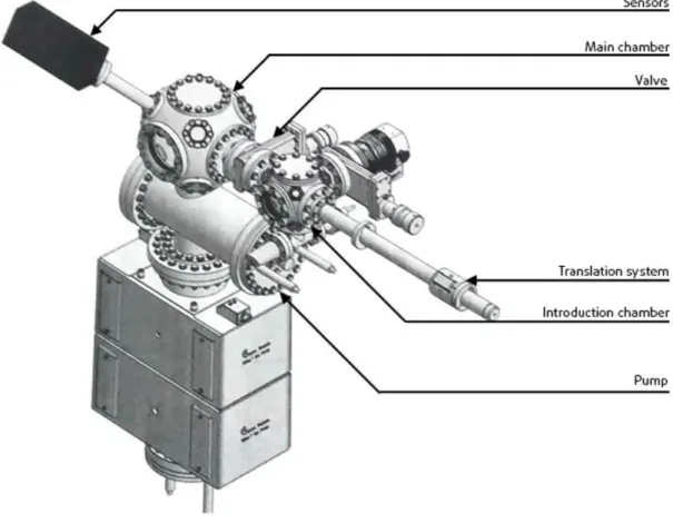
Double vacuum chamber
The solution to both problems is a double vacuum chamber system which can be found in figure 6. This system consists out of two vacuum chambers (introduction chamber and main chamber) and a connecting tube with a valve.
Using this system a sample is introduced in the introduction chamber. Hereafter a vacuum is created in this chamber. This is a relatively short process, because the introduction chamber is a small chamber. Hereafter, the valve in the connecting tube is opened and the sample is translated into the main chamber. The main chamber is a large chamber where the actual experiments can be conducted. Since the valve in the tube can be opened and closed, the main chamber is in a constant vacuum and does not have to be cured every time a sample is introduced. The result is that experiments can be conducted more quickly and more reliable.
29
8.3
Problem
CTI has the financial resources and the governmental permission to procure the double vacuum system including pumps and the equipment for the experiments. However, to translate the sample from the introduction chamber to the main chamber and back, a translation system (linear feedthrough) has to be installed. The linear feedthrough consists out of three systems; 1) a sample holder in the main chamber (sample holding system). 2.) A system to hold the sample while moving from the introduction to the main chamber (sample introduction system). And 3.) A system that provides the necessary linear movement (translation system). The latter system will be procured by CTI. However for financial reasons the first two have to be designed and manufactured by CTI self.
Assignment
Designing the sample holding and sample introduction system will be the assignment of part 2. To do this CTI provided two scenarios. In scenario 1 CTI will get a sample holding system from a different research institute, provided to them as a gift. This system is an advanced system, for example it can heat the sample. The dimensions of this holding system are based on Omicron dimensions and are standard for a lot of different types of equipment in vacuum research. Also used at CTI. So the objective of the first scenario is to design a sample introduction system that is compatible with the translation system, the provided sample holding system, and the Omicron samples.
It is not certain the research institute will provide CTI with an expensive sample holder, and therefore scenario 2 is set up. In the second scenario both the sample holding system and the sample introduction system have to be designed. The two systems have to be compatible with the translation system and the dimensions of the sample.
8.4
Conclusion
30
9
Analysis
The first step in designing the feedthrough is an extensive analysis. This includes constraints of designing equipment in a vacuum, discussed in section 9.1. The double vacuum chamber system, the sample, the translation system in section 9.2. And an analysis of the current products in section 9.3. The result of the analysis is a change in the assignment and a program of requirements in respectively section 9.4 and 9.5.
9.1
Vacuum
The main chamber is in a permanent (ultra high) vacuum where the pressure can go as low as 1.000.000 torr. This means that the sample transfer system and the sample holding system have to perform its function in a vacuum. This creates three constraints to the design. The first constraint is the rate of outgassing of the chosen material. Outgassing is the release of gas that is trapped inside a material when the material is in a vacuum. This gas can cause interference in the measurements, and therefore a material with a low rate of outgassing should be chosen (Elsey, 2002). Materials with a low rate of outgassing are; polished stainless steel 316L, copper mechanically polished, steel nickel plated, molybdenum, tungsten, and tantalum.
The second constraint is friction caused by two components of the same material that move beside each other. The friction causes a cold weld between the components making the system unusable. Therefore two components of the same material should not move beside each other.
The third constraint is that materials tend to deform in a vacuum over time. This means that the selected material should be very stiff. However, it is impossible to prevent small deviations regardless of the stiffness of the material. To account for the small deviations, the position of the systems should be adjustable from outside the chamber.
9.2
Existing parts
The translation system, double vacuum system, and the sample will be procured by CTI. Their dimensions and interfaces will cause boundary conditions, which should be taken into account.
Translation system
The translation system (figure 7) will be procured by CTI. The system consists of an outer tube, an inner rod, and a magnet around the outer tube. The inner rod is partly magnetic, so the outer magnet can manipulate the rod. However, the magnet is only able to perform two movements. A translation on the x-axes and 360⁰ rotation around its own axis. These movements cannot be separated from each other. 5
The sample introduction system is attached to the inner rod. This means that placing and removing the sample has to be executed with the two movements mentioned.
Sample
The thin film of which the working function is measured is be placed on an Omicron (sized) sample plate. The dimensions of the sample are standard and should be taken into account during the design phase.
5 The magnet will be manipulated by human hand. It is impossible for a human to either only translate, or only rotate. So both
31
The thin film of which the work function is measured is made using vacuum decomposition, and is therefore relatively expensive. Besides, as mentioned in section 8.2 it is not desirable to open the main vacuum chamber. So from both reason one can conclude that the sample must never drop inside the main vacuum chamber.
Double vacuum chamber
The only restriction from the double vacuum chamber is the connecting tube which has a diameter of 38 millimetres (mm). This implies that the introduction system should be smaller than 38 mm.
9.3
Market analyses
A market analysis is conducted to get an understanding of existing solutions. The result of this analysis can be found in the collage in figure 8.
Several observation can be made from this collage. The first is that most introduction systems are based on an “open and close” movement, like a beak. Secondly the sample introduction system is often guided by a pin that fits in the sample holding system. This can help both systems to line up with each other to account for small deviations. Lastly the sample holding systems often clamp the sample between two plates to hold it.
The collages is also used for inspiration for the idea phase.
33
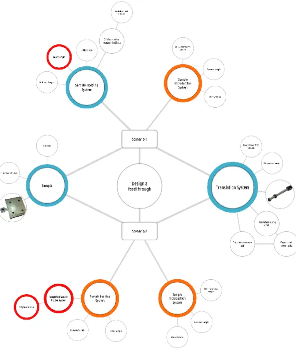
Figure 9: Overview of the two assignments. The red spheres indicate the difference between the two. The blue spheres are parts that are already designed. And the orange spheres have to be designed. A larger version of this image can be found in appendix 2.
9.4
Assignment
The original assignment is reviewed based on the analysis above. As mentioned the assignment consist out of two scenarios. To get a good understanding of the scenarios, the total assignment is depicted in figure 9 (a larger version can be found in appendix 2). Several conclusions can be drawn from this figure. Firstly, in both scenarios the interaction with the sample and the translation system is similar. Secondly, the requirements for the sample introduction system are similar in both scenarios. And lastly, there is just one difference between the sample holding system as a gift and the one that needs to be designed. The difference is that the one system heats the sample and the other does not. However this is not required, so it can be concluded that both scenarios are similar. Taking the above into account a new assignment is formulated that is faster to execute, and prevents double work. The assignment is formulated as:
“Design a sample holding system with the same dimensions as the sample holding system provided as a gift. And design a sample introduction system that is compatible with the sample holder system, the
34
9.5
Program of requirements
Based on the analysis, three separate programs of requirements are set up; the first contains general requirements for both systems; the second only the sample introduction system requirements, and the third contains requirements for the sample holding system.
General requirements
Should be made of non-magnetic materials
Should be made of materials with a low rate of outgassing Should be manufacturable at the CTI workshop
Maximum material costs of €200,- Should cause no friction
Sample introduction system
Restricts sample from falling in main chamber Should be guidable by sample holding system
Should place sample in holding system sing only rotation and translation Should remove sample from holding system using only rotation and translation Fit through a gap of 38 mm
No heavier than 500 gram
Compatible with the translation system
Compatible with the sample holding system provided as a gift
Sample holding system
Should be able to guide sample introduction system Should hold sample
Should release sample
Should be mountable in main vacuum chamber Should be adjustable in height
Should not create shadow over sample Should reduce interference
Should have similar dimensions as the sample holding systems provided as a gift
9.6
Conclusion
35
10
Sample introduction system
In this chapter concepts for a sample introduction system will be designed. In the next chapter the same will be done for the sample holding system. To design the concepts, firstly several ideas are created in section 10.1. Two ideas are selected in section 10.2 and further developed into concepts in section 10.3. Finally one final concept is selected in section 10.4.
10.1
Idea generation
The first step is creating multiple ideas for a sample introduction system. To do this, first ideas are generated to separate the rotation and translation movements. In the next paragraph the ideas to open and close (grab and release the sample) are explained.
Translation and rotation
As mentioned in section 9.2, the translation system that is procured by CTI cannot separate rotation and translation movements. This can result in dropping the sample. To avoid this, three ideas have been created to separate the movements. The ideas can be found in figure 10 on the next page.
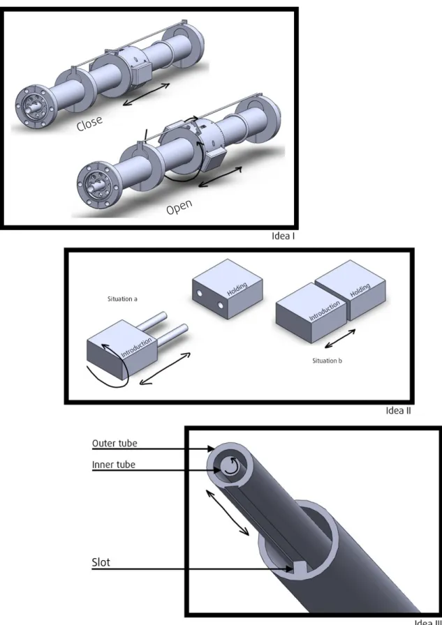
Idea I
Idea I attaches a guideline to the translation system. Theguideline has two positions: open and close. When the guideline is closed, the translation system can only translate the introduction system. When the guideline is open, the translation systems is able to translate and rotate. So when using this system a user closes the guideline when it only has to translate the sample. When the sample is at the holding system, the user can open the guideline and release the sample.
Idea II
For idea II a fork is positioned in front of the sample introduction system, and two corresponding holes are located in the sample holding system. When the fork is outside the holding system (situation a), the total introduction system can rotate freely. But when the fork is inside the holding system (situation b), the system is prevented from rotating. The two situations provide the opportunity to create an introduction system that can perform two different actions at two different positions.
Idea III
Idea III involves two separate tubes; an outer and an inner tube. Due to a slot in the tube, the outer tube can only translate the introduction system. The inner tube can both rotate and translate. By using to magnets and by connecting the right components to the right tube, the sample will either translate (outer tube) or open and close (inner tube).
36
37
Open and close
This section discusses the ideas to transport the sample from the introduction to the main chamber. The ideas discussed are all based on an open and close movements. The movements can only be generated by rotation and/or translation of the translation system. The ideas can be seen in figure 11 and 12.
Idea 1
Idea 1 consists of three components; A lower component, an upper component, and a pushing triangle. The working principle is based on two separate translation movements. In the first movement the introduction system is brought to the sample holder. The lower component is stopped by the holding system. The inner tube can still translate, and by doing this the triangle pushes the upper component up. Releasing the sample with a forward movement, a grabbing is with a backward movement of the inner tube.
Idea 2
Idea 2 consists of a lower and upper component, and of a set of gears. By rotating the magnet of translation system, the gear will drive the worm wheel. This creates an up and down movement of the upper component and thus grabbing the sample.
Idea 3
The third idea consists of a lower component, an upper component, and a rotating disk. By rotating the inner tube inside the translation system, the disk will open or close the upper component. To allow the upwards movement, the upper component has a slot were the rod can move sideways.
Idea 4
38
39
Idea 5
Idea 5 is similar to idea 3. The difference is that the inner tube directly rotates the upper component. This reduces the number of components, and thus the complexity.
Idea 6
Idea 6 consists of two components; a lower component, and a rod with a hook. When closed, the hook prevents the sample from falling. But by rotating the inner tube, the hook opens and releases the sample. And in a similar way, this idea can grab the sample.
Idea 7
The seventh idea consists of three components; lower component, upper component, and a rotating component that is attached to the inner tube. By rotating the inner tube, a small pin on the rotating component forces one side of the upper component down. This results in an upwards movement at the other side, thus releasing and grabbing the sample.
Idea 8
The eighth and final idea consist of three components. The lower component, the fixating component, and the rotating component. The fixating component inside the lower component is pushed sideward by a spring. This enables the fixation component to hold the sample. By rotating the rotating component the fixating component is pushed aside, releasing the sample.
10.2
Idea selection
In this section the ideas are reviewed and several ideas are chosen to be further developed. The selection has been executed in collaboration with CTI. The ideas are assessed on the feasibility of the working principle and the manufacturability of the idea. These criteria are difficult to measure, and are therefore mainly based on the experience of the colleagues at CTI and the workshop. Their opinions were gathered during an expert session organized by the author. The selection is executed by manner of eliminating the ideas that are found not feasible on the two above criteria. The ideas that are feasible will be further developed in the next section.
Translation and rotation
Firstly the ideas that prevent dropping the sample are selected. After consultation with the workshop it became clear that modifications to the translation system necessary for idea 3 cannot be executed at CTI. Therefore idea 3 is eliminated. The second eliminated idea is idea 1. This ideas is regarded as too difficult to operate. Idea 2 is regarded as feasible, and will be further developed.
Open and close
40
41
10.3
Concepts
This section discusses two concepts and the choice for a final concept. The concepts are based on the selected ideas in the previous chapter. The idea to prevent the sample from dropping down using a fork is integrated in both concepts.
Concept 1
Firstly the different components of the concept will be discussed and hereafter the working principle and the manufacturability. A rendered image of concept 1 can be found in figure 13.
Components
As can be seen in figure 13, concept 1 consist out of eleven components. Five components are standard and are available at CTI. Using standard components decreases the material costs for CTI. These components are:
Table 9: Bill of materials of the standard components of concept 1
# Component name Component Description Quantity
1 Large_bolt (Ø 9/64” x 25 mm) Large bolt 1
2 Retaining_ring_large (Ø 1/2") Large retaining ring 1
3 Small_bolt (M2 x 6.5 mm) Small bolt 1
4 Nut (Ø 9/64”) Nut 1
5 Retaining_ring_small (M2) Small retaining ring 1
The other six components are non-standard and have to be manufactured by the workshop of CTI. These are:
Table 10: Bill of materials of the non-standard components of concept 1
# Component name Component Description Quantity
6 Lower_component Lower component 1
7 Upper_component Upper component 1
8 Rotating_shaft Rotating shaft 1
9 Fork Fork 2
10 Gear Gear 1
11 Connecting_component Connecting component 1
Working principle
42
Figure 13: Graphical representation of concept 1. The upper image is a 3D render. The lower image is an exploded view.
Manufacturability
All the component are designed for easy manufacturability to ensure that CTI can manufacture them. The chosen material is mostly polished stainless steel 316L, as described in section 9.1. Only the connecting component and the rotating shaft are made of a different material. The connecting component should allow rotating of the translation system. To prevent a cold weld and to be able to act as a plain bearing, the component is made of polished bronze. The rotating staff is made of molybdenum. The staff should have a high stiffness to function as a gear, and it should not weld into the lower component. Molybdenum meets both requirements.
43
Concept 2
Firstly the different components of concept 2 will be discussed and hereafter the working principle and the manufacturability. Concept 2 is depicted in figure 14.
Components
As can be seen in figure 14, concept 2 consist out of twelve components. Of the twelve components, five components are standard and are available at CTI. These are:
Table 11: Bill of materials of the standard components of concept 2
# Component name Component Description Quantity
1 Large_bolt (Ø 9/64” x 15 mm) Large bolt 1
2 Retaining_ring_large (Ø 1/2”) Large retaining ring 1
3 Retaining_ring_small (M2) Small retaining ring 2
4 Nut (Ø 9/64”) Nut 1
5 Small_bolt (M2 x 6 mm) Small bolt 1
The other seven components are non-standard and have to be manufactured by the workshop of CTI. These are:
Table 12: Bill of materials of the non-standard components of concept 2
# Component name Component Description Quantity
6 Upper_component Upper component 1
7 Rod Rod 1
8 Fork Fork 2
9 Lower_component Lower component 1
10 Rotating_component Rotating component 1
11 Pushing_rod Pushing rod 1
12 Connecting_component Connecting component 1
Working principle
Similar to concept 1, concept 2 also has two situations; firstly when the fork is outside the sample holding system. In this situation the whole system can rotate freely. This is when the sample is transferred from the introduction chamber to the main chamber. To prevent the sample from dropping, a spring pulls the upper component down. Creating a fool proof system depicted in figure 14.
44
Figure 14: Graphical representation of concept 2. The upper image is a 3D render. The middle image is an exploded view. And the lower image shows the working principle of the spring.
sample holding system, so the sample cannot fall when the system is accidently rotated during transportation.
Manufacturability
45
10.4
Concept selection
One concept will be selected using a multi-criteria decision matrix. The input of the matrix will be the general requirements and the requirements for the introduction system. The result of the selection can be seen in table 13.
Table 13: The Multi-Criteria Decision Matrix for selecting a concept
Requirement Weight Concept 1 Concept 2
General requirements
Should be made of non-magnetic materials 10 10 10
Should be made of materials with a low rate of outgassing
8 8 8
Should not contain electrical components 10 10 10
Should be manufacturable at the CTI workshop 8 0 8
Maximum material costs of €200,- 5 5 5
Should cause no friction 8 0 8
Sample introduction system requirements
Restricts sample from falling in main chamber 10 10 10
Should be guidable by sample holding system 5 5 5
Should place sample in holding system using only rotation and translation
10 10 10
Should remove sample from holding system using only rotation and translation
10 10 10
Fit through a gap of 38 mm 10 10 10
No heavier than 500 gram 5 5 5
Compatible with the translation system 10 10 10
Compatible with the sample holding system provided as a gift
10 10 10
Overall - 103 119
The result from the Multi-Criteria Decision Matrix is that both concepts have almost similar scores. The difference (highlighted) is that the first concept has a lot of friction between the two gears. And the rotating shaft of the first concept is hard to manufacture due to the hardness of molybdenum and the difficult shape it has to be processed in.
46
10.5
Conclusion
47
11
Sample holding system
In this chapter the process of designing the sample holder system is described. This process is different than the previous process. On arriving at CTI a preliminary idea for a sample holder was already created and it only had to be converted into a concept and a final design. This process is described in section 11.2. In the next chapter the sample holding system and the sample introduction system will be simultaneously developed into final designs.
11.1
Idea
The idea as created by CTI can be seen in figure 15. It consist out of three components; upper component, lower component, and connecting rod. A sample is placed between the upper and the lower component.
As mentioned in section 8.1 the sample holding system should not contain acute angles. Therefore the shape of the holding system is an ellipse.
48
11.2
Concept
In this section the idea is developed into a concept. In this section the different components will be discussed first. And hereafter the working principle and the manufacturability will be analysed. The concept is depicted in figure 16.
Components
The concept consists out of 6 components, of which two are standard and available at CTI. The standard components are:
Table 14: The bill of materials of the standard components of the concept
# Component name Component Description Quantity
1 Bolt (M2 x 5mm) Bolt 1
2 Nut (M2) Nut 1
The four other components are non-standard. These are:
Table 15: The bill of materials of the non-standard components of the concept
# Component name Component Description Quantity
3 Tighten_ component Tighten component 1
4 Connecting_ component Connecting component 1
5 Upper_component Upper component 1
6 Lower_film Lower film 1
Working principle
The system holds the sample between the lower film and the upper component. To minimize the shadow on the sample, the lower film is just 1mm larger than the sample. This is assumed to be sufficient to hold the sample. The lower component is made of a film because this reduces the thickness and the costs of the total system. A flexible film will also help the sample entering the sample holder.
The system is connected to the vacuum chamber via a rod. The connecting component is a little larger than the rod itself, so the component can be tightened around the rod. Using this principle allows the sample holding system to be adjusted in height.
As mentioned in section 8.2, the main dimensions of this concept are similar to the standard Omicron sample dimensions. By doing this the sample introduction system can be used for both the new sample holder and the provided sample holder.
Finally the sample holding system contains two holes to guide the sample introduction system, and to allow for the chosen concept for the sample introduction systems. The holes also function as a stop for the introduction system, so the sample itself cannot be damaged of get stuck inside the holding system.
Manufacturability
49
All the component of the sample holding system can be made out of stainless steel 316L because all the components are stationary.
11.3
Conclusion
In this chapter the sample holding system has been developed up to a concept level. This is done by further developing the initial idea of CTI. The holding system will be further developed simultaneously with the development of the sample introduction system to make sure that they are compatible with each other.
50
12
Detailed Design
In this chapter the final design of the sample holding system, and the sample introduction system is shown. Firstly the sample holding system is developed in section 12.1. Secondly the sample introduction system is finalized in section 12.2. Finally the manufacturability of both systems is analysed in section 12.3. The final design of both systems can be found in figure 19.
12.1
Sample holding system
In this section the final design of the sample holding system will be discussed. This is done by firstly listing the different components, and thereafter the details of the design.
Components
The final sample holding system consists out of three components and can be seen in figure 17. The components are:
Table 16: Bill of materials of the final design of the sample holding system
# Component name Component Description Quantity
1 Upper_Component_Holding_System Upper component holding system 1 2 ISO 4026 – M3 X 5 – C Socket set screw at point M3 x 5 1
3 Lower_film Lower film 1
Details
Some changes have been made to the final concept in comparison to the concept of chapter 11. The first change is the connection with the rod. In the final concept the rod fits inside the lower component, and a screw is used to fix the component. To adjust the height, the rod is able to move up and down inside the lower component. Secondly the holes for the fork are extended through the whole body. This way the fork can never limit the sample introduction system. But it also means that another method has to be created to stop the sample introduction system. This will be discussed in the next section. Lastly, a chamfer has been added to the upper component to guide the sample entering.
51
12.2
Sample introduction system
In this section the sample introduction system chosen in section 10.4 is further developed. The working principle is still the same; however a few details are changed to improve the system. The final design of the sample introduction system is divided into four different assemblies. These will be discussed separately by first listing the different components and afterwards the details of the assembly. The components are discussed according to figure 18. In this figure the components are depicted the wrong side up. However, by doing this the assemblies are better visible. Figure 19 shows the total system in the right way.
Lower assembly
The lower assembly consists out of three components: Table 17: Bill of materials of the lower assembly
# Component name Component Description Quantity
4 Fork Fork 2
5 ISO 4026 – M3 X 5 – C Socket set screw at point M3 x 5 1
6 Lower_Component_Introduction Large bolt 1
Details
The lower assembly is changed in several aspects. Firstly the shape. The rectangular shape is easier to manufacture. And rounding’s are included for easy access of the milling machine. Secondly it is preferable if the forks can be adjusted in length for different types of sample holding systems. Therefore longer gaps have been made into the lower assembly, and the forks are fixed using screws. Thirdly, the sample is placed in a spacing. This helps getting the sample into the right position. The spacing is made a little lower than the sample itself to make sure that the upper component pushes on the sample and not the lower component. Lastly, an extension has been placed in front of the lower component. The extension will stop the sample holder system when the sample is placed correctly. This provides feedback for the user that the sample is placed, and prevents the sample from being damaged. The adjustment was necessary because the holes in the sample holding system are all the way through.
Upper assembly
The upper assembly is made of six components: Table 18: Bill of materials of the upper assembly
# Component name Component Description Quantity
7 Focus_pin Focus pin 1
8 ISO 4026 – M3 X 5 – C Socket set screw at point M3 x 5 1
9 Upper_Component Upper component 1
10 Rotating_Rod Rotating rod 1
11 Retaining_Ring_M3 Retaining ring 2