Abstract -In this paper, we present a new designed multi-view single camera and a novel model of scale and illumination invariant corner detection for a service robot in indoor environment. Vision-based simultaneous localization and mapping (VSLAM) has received much attention. It is used for VSLAM that are single cameras, multiple cameras in a stereo setup or omni-directional cameras. We propose a different approach which multiple mirrors are mounted on a vision system in a single-view-point (SVP) configuration. This vision system is easily to acquire no distortion image sequences without any preprocessing. Robust feature detection method is also described for VSLAM of a service robot in indoor environment. This method can detect scale and illumination invariant corner features in any environment.
Index Terms—Multi-view single camera, Feature detection,
Scale and illumination invariant corner feature (SIICF).
I. INTRODUCTION
Recently, cameras have been small and cheap sensors with low power consumption, which makes them suitable for large scale employment in commercial products such as robotic toys and security robot. Various types of cameras including pin-hole, stereo, omni-directional and non-central camera have been used in robot vision. These vision systems posses the characteristics of either a narrow field of view (FOV) or a wide FOV but suffer from complex distortion.
The most widely used vision system is stereo rigs composed of two perspective cameras. Since ordinary cameras have limited FOV, one can get stereo range in only one direction at a time. But, the restricted FOV of single cameras and traditional stereo setups causes the limited function of service robots. Service robots need to survey more widen environment around it constantly in real-time in order to avoid obstacles and perform more advanced functions, such as VSLAM and object tracking. Thus, many researchers have added rotational device to get the
Manuscript received July 30, 2008. This work was supported in part by the Japan Society for the Promotion of Science (JSPS).
Jegoon RYU is with the Graduate school of Information, Production and Systems, Waseda University, 808-0135 Japan (e-mail: [email protected] ).
Kunsu HWANG is with the Graduate school of Information, Production and Systems, Waseda University, 808-0135 Japan (e-mail: [email protected] ).
Hyunkyung PARK is with the Graduate school of Information, Production and Systems, Waseda University, 808-0135 Japan (e-mail: [email protected] ).
Byeongcheol YOO is with the Graduate school of Information, Production and Systems, Waseda University, 808-0135 Japan (e-mail: [email protected]).
Toshihiro NISHIMURA is with the Graduate school of Information, Production and Systems, Waseda University, 808-0135 Japan (e-mail: tosi-hiro@ waseda.jp ).
omni-directional view. This system is better to obtain good resolution, but it requires the rotation of the cameras and this prevents treating scenes with moving objects. Some fixed cameras have been also used to avoid the time-consuming scanning. This system can achieve high resolution omni-directional image with very high costs. However, it is difficult to force all cameras to be calibrated and synchronized [1]-[6]. To overcome the problem, catadioptric omni-directional system is widely used over both the scanning method and multi-camera method, because of system simplicity. Catadioptric systems that use a curved mirror to map a panoramic view onto a single sensor are able to achieve a single view point at video rate. No mechanical rotation is needed [7][8]. But, even though omni-directional cameras provide a whole view around it, they suffer from an unfavorable spatial distribution of the available resolution. We propose to use a novel multi-mirror setup that is mounted on the vision system in a SVP configuration. The mirrors face in four different directions. This multi-view single camera combines the advantages of omni-directional camera with those of single cameras. In contrast to single camera and traditional stereo cameras, the vision system provides a wider FOV, leading to better constraints for VSLAM. And in contrast to omni-directional cameras, which distribute the available pixels over the complete scene, a multi-view single camera can focus the available resources on interest areas depending on the application.
In this paper, we also describe a novel model to perform the robust feature detection in indoor. Visual SLAM has been an interesting topic in mobile robotics for the last years. The approaches using vision apply a feature-based SLAM, in which visual features are used as landmarks. The main key in VSLAM is how to select suitable features on the images to be used as reliable landmarks. Various algorithms have been established for feature detection, including scale-invariant feature detection (SIFT) by Lowe [12][13]. In his system, a trinocular sensor is used to generate 3D landmark points from a single robot pose.Though the algorithm gives very good resulting output, it is unfortunately very computationally intense and also requires a lot of data for each feature detected. Some attempts of further improvements to the algorithm have been made, such as PCA-SIFT by Ke and Sukthankar[14]. Another promising approach is the speed up robust features (SURF) by Bay et al. [21], which has been shown to yield comparable or better results to SIFT while having a fraction of the computational cost.These methods are strong to scale and notation transform, but illumination changing has a weak property. A service robot in indoor requires illumination-robust feature detection. This paper presents a novel model to perform the scale and illumination invariant feature detection in indoor environment.
Robust Feature Detection of a Service Robot
using Multi-view Single Camera in Indoor
II. MULTI-VIEW SINGLE CAMERA
A geometric structure of the proposed system and characteristics of images captured by the proposed system are described in this section. Most ordinary cameras used in machine vision either possess a narrow FOV or have a wide FOV, but suffer from complex distortion. It can be difficult to unwrap a wide FOV image to perspective projection views accurately. The proposed vision system can have the broad FOV and acquire low distortion and lossless scene. This vision system uses five planar mirrors for SVP multi-view mirror setup and a conventional camera. Four mirrors have the property of an isosceles trapezoid and a base mirror is rectangular form. The shape of each planar mirror plays a leading role to solve serious distortion problem of catadioptric omni-directional vision system.
This vision system locates the single-view-point (SVP) on the axis of symmetry of the multi-view mirror setup. This viewpoint is placed at the top of the vision system. It can be easily accomplished by starting with a viewpoint located inside the mirror setup and projecting its image into the physical world by finding the reflections of the viewpoint in the planes containing each respective mirror face. Each projection of four planar mirrors is the location of the bottom mirror. The SVP is well defined in the projective pin-hole camera imaging model, and each lens camera is modeled as a point in space and an image plane.By definition, all normal lens cameras in the perspective pin-hole model meet the SVP
(a)
[image:2.595.56.280.51.527.2](b)
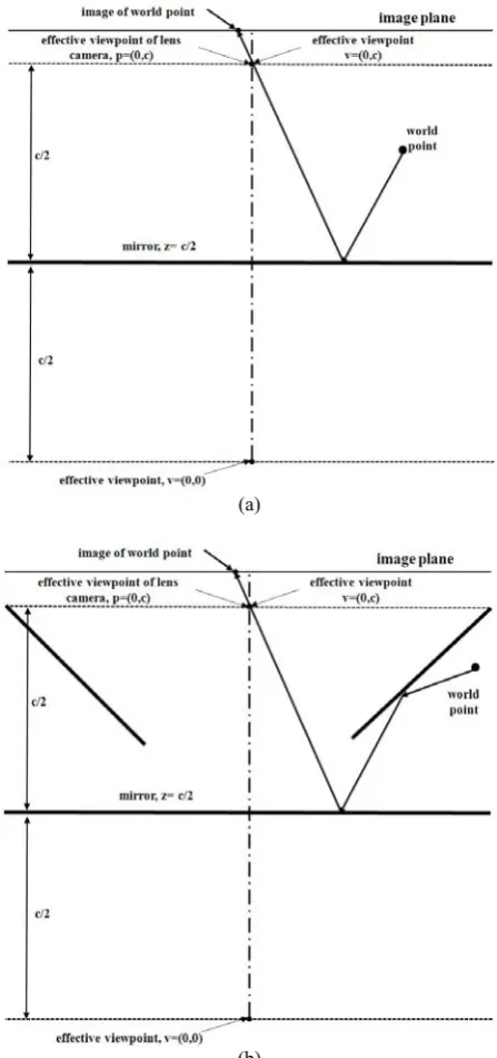
Fig. 2. Ray tracing illustration of the multi-view single camera. (a) shows the configuration of the multi-view mirror setup, (b) illustrates the ray tracing.
(a)
(b)
[image:2.595.320.522.53.583.2]condition. Fig. 1 illustrates the imaging model of an SVP multi-view mirror system.Given the geometric configuration of the mirror and the camera, for any given world point, we
can find its corresponding image point by finding the virtual object point behind the mirror surface.Once the virtual object is determined, it can be viewed just like a real object such that its image is found by drawing a line from the virtual object point toward the viewpoint until it intercepts the image plane. Ray-tracing which has a different meaning in the geometric optics model is the other way to describe the imaging of an SVP multi-view mirror system. If we have an algorithm such that, given any world point, one can traces the light ray via a unique path to a unique image point on the image plane, we have projection. If every such unique ray path for every given world point passes through the SVP of both the mirror and the camera, we have met the SVP condition. These ray paths must not violate the law of reflection; however, the law of the refraction is a nonissue because the lens component is represented by an ideal pin-hole. The multi-view mirror setup can also be proven to be SVP by ray tracing, as shown in Fig. 2.
After placing the camera at the location dictated by the viewpoint in a given multi-view mirror setup, we need to determine some parameters of physical camera such as orientation and focal length. It also decides the size of the camera image sensor and the field of view. The minimum requirement for camera here is to be able to capture, on its sensor, a complete image of its corresponding bottom mirror face. This bottom mirror face image from the camera consists of the images projected from four isosceles trapezoid mirrors. This requirement may not ensure optimal parameters of the available camera sensor. In other words, the image of a bottom mirror face on a camera sensor may be larger than the
(a)
(b)
(c)
[image:3.595.354.496.49.372.2](d)
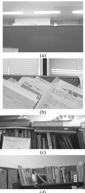
Fig. 7. One image captured by multi-view single camera. (a) is the front side image, (b) is the back side image, (c) shows the left side image, (d) shows the right side image.
(a) (b)
[image:3.595.103.232.56.181.2](c)
[image:3.595.109.230.217.302.2]Fig. 6. Multi-view single camera. (a) is the configuration of the proposed vision system, (b) and (c) show the side image of the multi-view single camera.
Fig. 5. The geometry of the multi-view mirror setup.
[image:3.595.67.263.350.480.2]Fig. 4. Variations in the mirror face image as the camera focal length and orientation changes.
[image:3.595.60.273.514.708.2]sensor, and thus not fully utilize the sensor. Fig. 3 represents the projection geometry of a bottom mirror face onto the sensor plane of a camera. The image sensor is perpendicular to the optical axis and parallel to the image plane which matches with the sensor plane. The focal length and the size of the image sensor can determine the effective field of view of the camera. Given the orientation and position of a camera in Fig. 3, we can then find the optimal focal length such that the bottom mirror face image is contained in the sensor capture area. Fig. 4 shows an example of the range of a bottom mirror face images projected on the sensor plane as a camera focal length and orientation changes. It can be seen that changes in orientation and focal length affect the location, size, and shape of the face image.
Fig. 5 illustrates the geometry of the multi-view mirror setup. This multi-view mirror setup can be characterized by the following parameters: radius (γ), tilt angle (θ), height (h), and the number of faces in Fig. 5. Radius stands for the perpendicular distance from the main axis to the line of intersection of each mirror face with the top of the system. Tilt angle stands for the angle between each mirror face plane and the top plane. The distance between the top plane and base plane is height of this system. Finally, the number of faces stands for the number of mirror faces.
Fig. 6 and Fig. 7 present the configuration of the proposed multi-view single camera and the captured images. The system components used in Fig. 5 are a Logitech QuickCam Pro 9000, Carl Zeiss lens, and a multi-view mirror setup of 18×13.5×12.5 cm size.
III. ROBUST FEATURE DETECTION
The evaluation of interest point detectors presented in Schmid [15] demonstrate an excellent performance of the Harris detector compared to other existing approaches. This detector however is not invariant to scale changes. In this section we propose a new interest point detector that combines the reliable Harris detector [11] with scale selection [16][17] and intensity changing to obtain a scale and illumination invariant detector.
Difference of Gaussian (DoG) algorithm has been used mainly to extract feature points, and to make the descriptor of feature point, scale invariant feature transform algorithm has been used. In complex environment, feature points are extracted easily. But, in simple environment and illumination changes, it is hard to extract reliable feature points. In this study, corner points are considered in the model of feature detection. However, corner points are very weak at scale transform. The scale and illumination invariant corner feature (SIICF) for an indoor environment is thus proposed in Fig. 8 and Fig. 9.
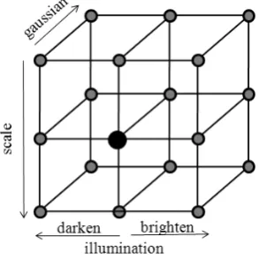
The proposed algorithm utilizes the modified Gaussian pyramid including intensity changes. For changing intensity, the brightness of image is performed at down sampled images. η + = ( , ) ) ,
(x y Dx y
F (1)
where D(x,y) is a down sampled image, η is the scale of brightness or darkness.
The Gaussian pyramid images are computed by convolving the intensity changing image F(x, y) with a Gaussian function of standard deviation σ, to obtain a blurred image of input image. ) , ( ) , , ( ) , ,
(x y Gx y Fx y
B σ = σ ∗ (2)
where * is the convolution operator in x and y plane. The Gaussian function :
2 2 2 2 ) ( 2 2 1 ) , , ( σ πσ
σ e x y
y x G
+ −
= (3)
is applied to B(x, y, σ) sequentially obtaining B(x, y, kσ) where kσ represents the number of convolutions applied to the intensity change image.
[image:4.595.313.528.49.161.2] [image:4.595.353.500.200.347.2]where σIis the integration scale, σDis the differentiation scale
and Lx and Ly is the derivative computed in the x and y direction, respectively. The matrix describes the gradient distribution in a local neighborhood of a point. The local derivatives are computed with Gaussian kernels of the size determined by the local scale σD(differentiation scale). The
derivatives are then averaged in the neighborhood of the point by smoothing with a Gaussian window of size σI
(integration scale). The eigenvalues(λ1, λ2) of this matrix will be proportional to the principle curvatures of the image surface and form a rotationally invariant description of H. This property enables the extraction of points, for which both curvatures are significant that is the signal change is significant in the orthogonal directions i.e. corners, junctions etc. Such points are stable in arbitrary lighting conditions and are representative of an image. One of the most reliable interest point detectors, the Harris detector is based on this principle. The Harris measure combines the trace and the determinant of the second moment matrix:
2 2 1 2 1
2
) (
) trace ( det
λ λ α λ λ
α + − =
+
= H H
f
(5)
Local maxima of f determine the location of interest points.
IV. IMPLEMENTATION AND EXPERIMENTAL RESULTS
We have implemented and tested our method using a custom made multi-view single camera that utilizes a conventional web camera. The mirrors are evenly distributed along four sides on the vision system, facing outwards as shown in Fig. 10(a) and the resolution is 1600 ×1200 size.
Fig. 10(b) is a picture taken indoors. Fig. 11 represents unwrapped view images from the multi-view mirror setup of Fig. 10. The image quality is close to that of an ordinary camera with the same lens and sensor.
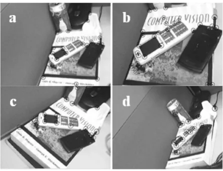
For evaluating the proposed model, we use the scale, notation, and affine transform images in indoor environment. And, the proposed method is compared with other feature detection methods. Fig. 12 shows the result of the proposed method using various change images.
V. CONCLUSION AND FUTURE WORK
We have presented a new designed multi-view single camera for wide FOV, no distortion, and lossless information, and robust feature detection method for a simple indoor environment. This vision system is easily to acquire no distortion image sequences without any preprocessing. The SIICF method can detect scale and illumination invariant corner point for any environment. We showed the basic effectiveness for a VSLAM technique with the proposed vision system and method.
[image:5.595.314.538.50.221.2]In the vision system,we had limitations on the achievable camera orientations and employed lens for focal length optimal to capture the bottom mirror face image. The most significant implication of these limitations is that the usage of commercial camera may not be optimized. However, the multi-view mirror setup validates the basic design experimentally that it is possible to construct a multi-view single camera.
Fig. 12. Scale and illumination invariant corner detection. (a) is an original image, (b) is a scale transform image, (c) is a notation transform image, (d) is an affine transform image.
(a) (b)
[image:5.595.60.278.458.554.2](c) (d)
Fig. 11. Image captured by multi-view single camera. These images are not calibrated for unwrapping. (a), (b), (c) and (d) are the front, back, left and right side image, respectively.
[image:5.595.304.537.465.532.2]
(a) (b)
Fig. 10. Implementation of the multi-view single camera. (a) shows the multi-view single camera, (b) is the image captured by the vision system.
Table. 1. Threshold, number of detected points and calculation time for the detectors comparison with Laplace of Gaussian (LoG), Difference of Gaussian (DoG), and Harris-Laplace. The images of the test set (50 images) were taken under various conditions
Method LoG DoG Harris-
Laplacian SIICF
Threshold 600 default 2500 500
nb of point 207 1520 153 353
Comp.
[image:5.595.58.280.611.736.2]In our ongoing work, we are investigating the use of this multi-view single camera in area such as mobile robot, and the multi-view mirror setup for a wider FOV and less distortion by setting lenses.
REFERENCES
[1] Sarachik, K. B., “Characterizing an indoor environment with a mobile robot and uncalibrated stereo”, Proceeding of IEEE International Conference on Robotics and Automation, vol. 2, pp. 984-989, 1989.
[2] Ishiguro, H., Yamamoto, M., and Tsuji, S., “Omni-directional stereo for making global map”, Proceeding of IEEE International Conference on Computer Vision, pp. 540-547, 1990.
[3] Ishiguro, H., Yamamoto, M., and Tsuji, S., “Omni-directional stereo”, IEEE Transaction on Pattern Analysis and Machine Intelligence, vol. 14, no.2, pp. 257-262, 1992.
[4] Kang, S. B. and Szeliski, R., “ 3-D scene data recovery using omnidirectional multibaseline stereo”, International Journal of Computer Vision, vol. 25, no. 2, pp. 167-183, 1997.
[5] Krishnan, A. and Ahuja, N., “Range estimation from focus using a non-frontal imaging camera”, International Journal of Computer Vision, vol. 20, no. 3, pp. 169-185, 1996.
[6] Murray, D. W., “Recovering range using virtual multi-camera stereo”, Computer Vision and Image Understanding, vol. 61, no. 2, pp. 285-291, 1995.
[7] Nayar, S. K., “Sphereo: Recovering depth using a single camera and two specular spheres”, Proceedings of SPIE: Optics, Illumination, and Image Sensing for Machine VisionII. 1988.
[8] Nayar, S. K., “Catadioptric omni-directional cameras”,
Proceeding of IEEE Conference on Computer Vision and Pattern Recognition, pp. 482-488, 1997.
[9] Baker, S. and Nayar, S. K., “A theory of single-view point catadioptric image formation”, International Journal of Computer Vision, vol. 35, no. 2, pp. 175-196, 1999.
[10]Murray, D. W., “Recovering range using virtual multi-camera stereo”, Computer Vision and Image Understanding, vol. 61, no. 2, pp. 285-291, 1995.
[11]Harris, C. G. and Stephens, M., “A combined corner and edge detector”, Proceeding of the Fourth Alvey Vision Conference,
pp. 147-152, 1988.
[12]Lowe, D. G., “Distinctive image features from scale-invariant key-points”, International Journal of Computer Vision, vol. 60, no. 2, pp. 91-110, 2004.
[13]Lowe, D. G., “Object recognition from local scale-invariant features”, Proceedings of the International Conference on Computer Vision, pp. 1150-1157, 1999.
[14]Ke, Y., Sukthankar, R., “PCA-SIFT: A more distinctive representation for local image descriptors”, Proceeding of IEEE Conference on Computer Vision and Pattern Recognition, vol. 2, pp. 506-513, 2004.
[15]Schmid, C., Mohr, R., Bauckhage, C., “Evaluation of interest point detectors”, International Journal of Computer Vision, vol. 37, no. 2, pp. 151-172, 2000.
[16]Lindeberg, T., “Feature detection with automatic scale selection”, International Journal of Computer Vision, vol. 30, no. 2, pp.79-116, 1998.
[17]Lindeberg, T. and Garding, J., “Shape-adapted smoothing in estimation of 3-D shape cues from affine deformations of local 2- D brightness structure”, Image and Vision Computing, vol. 15, no. 6, pp. 415-434, 1997.
[18]Davison, A.J., “Real-time simultaneous localization and mapping with a single camera”, Proceeding of International Conference on Computer Vision, pp. 1403-1410, 2003. [19]Hartley, R. and Zisserman, A., “Multiple View Geometry in
Computer Vision”, Cambridge University Press, 2000. [20]Se, S., Lowe, D., and Little, J., “Mobile robot localization and
mapping with uncertainty using scale-invariant visual
landmarks”, International Journal of Robotics Research, vol. 21, no.8, pp. 735-758, 2002.
[21]Bay, H., Tuyelaars, T., and Van Gool, L., “Surf: Speeded up robust features”, Proceeding in the ninth European Conference on Computer Vision, Lecture notes in computer science, vol. 3951, pp. 404-417, 2006.