Abstract— The formulation of finite elements based on the strain approach has continued in recent years and many elements were developed; for general plane elasticity problems, plate bending and shells elements. This approach leads to the representation of the displacements by higher order polynomial terms without the need for the introduction of additional internal and unnecessary degrees of freedom. Good convergence can also be obtained when the results are compared with those obtained from the corresponding displacement based elements, having the same total number of degrees of freedom. Furthermore, the membrane elements remain stable with geometrical distortions and plate bending elements are free from any shear locking since they converge to the Kirchhoff solution for thin plates contrarily for the corresponding displacement based elements. The main objective of this paper is to present the efficiency and the performance of the strain based approach compared to well known displacement formulation; and this is through some validation tests using elasticity plane elements, bending plates and shell elements
.
Index Terms— Displacement formulation, Elasticity plane element, Finite elements, Plate bending, Strain Approach.
I. INTRODUCTION
HE analysis and design of structures is a topic of interest in a variety of engineering disciplines. In problems of structural mechanics the analyst seeks to determine the distribution of stresses throughout the structure to be designed. It is also necessary to calculate the displacements of certain points of the structure to ensure that specified allowable values are not exceeded. When dealing with the continuum structures, the finite element method is more suitable and powerful tool of analysis, one can vary the size, the shape, the thickness and the material property of an element to suit the overall property of the structure which makes it particularly appropriate for complicated problems involving non-homogeneous material
Manuscript received February 12, 2010, Efficiency of the Strain Based Approach Compared to the Displacement Formulation for the Analysis of Structures.
Djamal HAMADI, Civil Engineering and Hydraulics Department Faculty of Sciences and Technology, Biskra University B.P. 07000 – Algeria, fax: 00 21333741038; (e-mail: [email protected]).
Abdelhafid OUNIS Civil Engineering Department, Faculty of Sciences and Engineering Sciences, Biskra University, B.P. 07000, Algeria fax: 0021333741038; (e-mail: [email protected]).
Cedric D'Mello, School of Engineering and Mathematical Sciences, City University, Northampton Square London EC1V OHB, U.K. Fax: +44 (0) 20 7040 8570 (email: C.A. D'[email protected])
properties, such as composite structures. Numerically it had been observed that the finite element method often leads to convergent results as the number of elements is increased. Along with the development of high speed computers, the application of the finite element method also progressed at a very impressive rate. Thereafter within a decade, the potentialities of the method for the solution of different types of applied science and engineering problems were recognised, and many books have been written on the finite element method [1] received worldwide diffusion. On the development side, many researchers continue to be preoccupied with the problem of the formulation of new elements, and further development of improved algorithms for special phenomena. At the same time a new approach of elements was developed at Cardiff University, referred to as the strain based approach. This approach is based on the calculation of the exact terms representing all the rigid body modes and the other components of the displacement functions which are based on assumed independent strain functions; insofar as it is allowed by the elasticity compatibility equations. With the continuation of the development of elements based on the strain approach, many elements were developed for general plane elasticity problems as well as shells by Sabir et al [2]–[4]. Furthermore, with the success of the application of the strain approach to the plane elasticity problems, the extension of the work to the development of finite elements in polar coordinates has continued [5 ]–[7], the results obtained for the various components of stresses were satisfactory and converged to the theoretical solution as the number of elements was increased. Some other elements for shells and three- dimensional elasticity have been also developed by Djoudi et al [8], Sabir et al [9], Belarbi et al [10], and Assan [11]; from the validation tests, these elements have been shown to produce results of an acceptable degree of accuracy without the use of large number of elements. Lately, Djoudi and Bahai have developed a new strain based shell element for the linear and nonlinear analysis of cylindrical shells[12] and two other elements for vibration analysis of shell structures [13], [14] the effectiveness of these elements was demonstrated and the convergence were also undertaken. Belounar and Guenfoud have also developed a new rectangular plate bending element for thin and thick plates based on the strain based approach and the Reissner/Mindlin theory [15]. A new rectangular element was elaborated for the general plane elasticity by Belarbi & Maalem [16]. Most recently, a new quadrilateral element
Efficiency of the Strain Based Approach
Compared to the Displacement Formulation for
the Analysis of Structures
D. HAMADI1, A. OUNIS2, and C.A. D'Mello3
was formulated for the general plane elasticity by Hamadi et al [17]; it is a simple element and has only two degrees of freedom per node. The various numerical examples show the performances of the strain based approach. It can be said that the formulated element remains stable with geometrical distortions. Finally, the main objective of this paper is to present the efficiency and the performance of the strain based formulation compared to well known displacement formulation; and this is through some validation tests using membrane elements, bending plates and shell elements.
II. DIFFERENT FORMULATIONS
According to the choice of the interpolation field several models of the finite elements can be generated which are: A. Displacement model
This model is the most popular and most developed. In this model, the finite elements are based on an interpolation of the displacements field. The displacements are determined in a single and detailed way in the structure, whereas the stresses are not continuous at the boundaries. B. Stress model
In this model the element is formulated on the base of stress field approximation only.
C. Mixed model
This model is based on two independent interpolations of two or more various unknown fields, generally the displacements fields and stresses fields within the element. In general this model takes the unknown parameters of these fields as degrees of freedom.
D. Hybrid model
This model takes in consideration an assumed stress distribution within the element and assumed displacements along its edge.
E. Strain Based Approach
This approach is based on the calculation of the exact terms representing all the rigid body modes and the other components of the displacement functions; which are based on assumed independent strain functions insofar as it is allowed by the elasticity compatibility equations.
III. ADVANTAGEOUS OF THE STRAIN BASED APPROACH
Direct interpolation based on the strain approach provides a better precision on these values and on constraints and displacements (obtained by integration); compared to the classic formulation where deformations are obtained by derivation of the chosen displacement fields.
The main advantages of this approach are [18], [19]: Easy satisfaction of the main two convergence criteria bound directly to strains (constant strains and rigid body movement).
Effortlessly decoupling of the various strain components (a field of uncoupled displacements generates coupled
strains).
Possibility of enriching the field of displacements by terms of high order without the introduction of intermediate nodes or of supplementary degrees of freedom (allowing so to treat the problem of locking).
IV. STRAIN BASED APPROACHFORMULATION
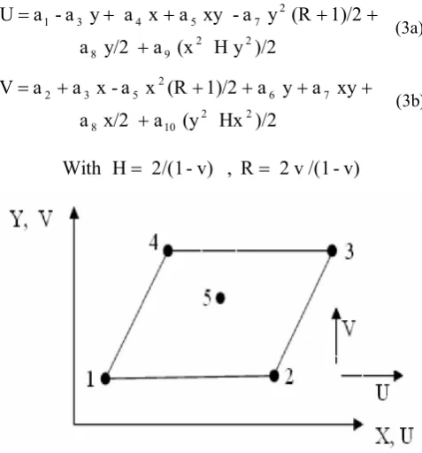
As an example for the strain based formulation, the description of Q4SBE1 (Strain Based Quadrilateral In-plane Element with An Internal Node) element will be given in this section.
Figure 1 shows the geometric properties of Q4SBE1 element, the corresponding nodal displacements. At each node (i) the degrees of freedom are Uiand Vi.
The three components of the strain at any point in the Cartesian coordinate system are given in terms of the displacements U and V:
x
U
x
(1a)
y
V
y
(1b)x V y U xy
(1c) If the strains given by equations (1) are equal to zero, the integration of these equations allows obtaining the following expressions:y a -a
U 1 3
(2a)
x
a
a
V
2
3(2b)
Equations (2) represent the displacement field in terms of its three rigid body displacements. The displacement fields of the Q4SBE1 element are given by the following equations (3): )/2 y H (x a y/2 a 1)/2 (R y a xy a x a y a -a U 2 2 9 8 2 7 5 4 3 1 (3a) )/2 Hx (y a x/2 a xy a y a 1)/2 (R x a x a a V 2 2 10 8 7 6 2 5 3 2 (3b) v) /(1 v 2 R , v) -2/(1 H [image:2.595.307.546.514.770.2]With
The evaluation of the element stiffness matrix is summarized with the evaluation of the following well known expressions Eqs. (4):
1
1. .
.
A
Q D Q dx dy AK T
S T
e (4a)
10
1
A
K
A
K
e T(4b)
With:
K
Q
D
.
Q
.
dx
dy
s
T
0
(4c)
V. NUMERICALAPPLICATIONS
The efficiency of the strain based approach will be shown through the following applications, using some strain based elements formulated recently (Q4SBE1, SBH8, SBP8C, ACM_Q4SBE1 and ACM_SBQ4) compared to the results obtained from some corresponding displacement elements. A. Mac-Neal's elongated cantilever beam (Membrane Elements)
Let us consider the example of the elongated cantilever beam(Fig.2) of Mac-Neal and Harder 20, with rectangular section (6 x 2 x 1) deformed in pure bending by one moment at the end (M =10) and by a load applied at the free end (P=1).
case (2) case
(1) 10 1 0,2
1 1 1 1 1 1
a) Regular Shape Elements
45° 45°
10 1 b) Trapezoidal Shape Elements
Data : E=107 , =0,3 , L=6 , t=0,1
45°
10 1
c) Parallelogram Shape Elements
Fig.2. Mac-Neal's elongated beam subject to (1) end shear and (2) end bending.
The cantilever is modelled by six membrane elements rectangular (Fig.2a), trapezoidal (Fig.2b) and parallelogram (Fig.2c). The results obtained for Q4SBE1 are compared with those obtained with other known quadrilateral
elements (Table I).
Mac-Neal [21] affirms that the trapezoidal shape of the membrane finite elements with four nodes without degrees of freedom of rotation (with linear fields) generates a locking even if these elements pass the patch-test. This problem is known as "trapezoidal locking".
NOTE. — This rule does not apply to the finite elements based on the strain approach.
The results obtained for elements Q4 and PS5 (Table 1) show well the problem of trapezoidal locking announced by Mac-Neal [21].
Through these three cases of meshes (Figs. 2a, 2b, 2c), the efficiency of Q4SBE1 element is confirmed. In conclusion, it can be said that "Q4SBE1" element is very powerful for this type of problems dominated by bending, and it remains stable with geometrical distortions.
B. Simply Supported Square Plate (Plate Elements)
The test of the simply supported square plate is examined with either a uniform loading (q = 1) or with a concentrated load (P = 1) at the centre (Fig.3). The quarter of the plate is divided into a mesh of N x N elements. The convergence tests are carried out on two different L/h ratios of 10 and 100 for thick and thin plates respectively. The results for the central deflection are given in Table II and Table III.
L
Fig.3: Simply supported square plate (L = 10, h = 1. or 0.1, E =10.92, = 0.25)
The numerical tests show that:
The strain based elements SBP8C and SBH8 have quite rapid rate of convergence to reference solutions for both thick and thin plates. They are free from any shear locking since it converge to the Kirchhoff solution for thin plates, contrarily for the corresponding displacement based element DBB8
C. Scordelis-Lo roof (shell elements)
The next test to be considered which is frequently used to test the performance of shell element is that of Scordelis-Lo roof having the geometry as shown in Fig.4. The straight edges are free, while the curved edges are supported on
Sym.
Sym.
rigid diaphragms along their plan. The geometrical and mechanical characteristics are given in Fig.4. Considering the symmetry of the problem only one quarter of the roof is analysed (part ABCD).
The results obtained by the combined flat shell elements
ACM_Q4SBE1 and ACM_SBQ4, for the vertical
displacement at the midpoint B of the free edge and the centre C of the roof are compared to the reference values based on the deep shell theory. Furthermore, the convergence of this element is also compared to other kinds of quadrilateral shell elements Q4
24, DKQ24 [29] and ACM-SBQ4 [30] Figs.5 and 6. The analytical solution based on the shallow shell theory is given by Scordelis and Lo [31], which is slightly different from the deep shell theory.Convergence curves (Figs.5 and 6) show the good contribution of the strain based approach.
Fig4. Scordelis-Lo roof
TABLE I: NORMALISED TIP DEFLECTION FOR MAC-NEAL'S ELONGATED BEAM
Pure bending End shear
Element
Regular Trapezoidal Parallel Regular Trapezoidal Parallel
Q4 0,093 0,022 0,031 0,093 0,027 0,034
PS5[22] 1,000 0,046 0,726 0,993 0,052 0,632
AQ [23] 0,910 0,817 0,881 0,904 0,806 0,873
MAQ [24] 0,910 0,886 0,890 0,904 0,872 0,884
Q4 [25] - - - 0,993 0,986 0,988
Q4SBE1 1,000 1,000 1,000 0,993 0,994 0,994
Theory 1,000 (0,270) 1,000 (0,1081)
TABLE II:CENTRAL DEFLECTION OF A SIMPLY SUPPORTED PLATE WITH A UNIFORM LOAD
4
qL
wD
x100
L/h=10 L/h=100
Mesh SBP8C
[26]
SBH8 [10]
DBB8 SBP8C [26]
SBH8 [10]
DBB8
2x2 0.3812 0.326 0.2283 0.0349 0.0523 0.0045
4x4 0.4218 0.4048 0.351 0.2563 0.3081 0.0171
8x8 0.4229 0.4145 0.3982 0.3856 0.3883 0.0582
12x12 0.4270 0.4249 0.4171 0.4033 0.4029 0.0786
Exact solution [27] 0.427 0.406
Where: D = Eh312(1-2)
TABLE III:CENTRAL DEFLECTION OF A SIMPLY SUPPORTED PLATE WITH A CONCENTRATED LOAD
2
PL
wD
x100
L/h=10 L/h=100
Mesh SBP8C
[26]
SBH8 [10]
DBB8 SBP8C
[26]
SBH8 [10]
DBB8
2x2 1.1745 0.9907 0.7269 0.113 0.1452 0.0134
4x4 1.321 1.243 1.097 0.789 0.8387 0.0481
8x8 1.363 1.333 1.289 1.108 1.115 0.1636
12x12 1.372 1.364 1.344 1.152 1.145 0.2269
Kirchhoff solution
[27] 1.16
0,5
0,51
0,52
0,53
0,54
0,55
0,56
0,57
0
10
20
30
40
50
60
70
Fig.5. Convergence curve for the deflection Wc at point C.
3,2
3,3
3,4
3,5
3,6
3,7
3,8
0
10
20
30
40
50
60
70
Fig.6. Convergence curve for the deflection Wc at point B.
Number of elements
Verti
ca
l
defl
ec
ti
on W
C
at
point
C
Wc ref. = 0.541 cm
ACM_Q4SBE1
Analytical ACM_SBQ4 Q4
24 DKQ24WB ref = - 3.61 cm
Verti
ca
l
defl
ec
ti
on
W
B
at
point
B
Number of elements
ACM_Q4SBE1
VI.CONCLUSION
From the numerical applications and the results obtained for different strain based elements used, the following conclusions can be drawn:
The membrane element "Q4SBE1" is very powerful for the problems dominated by bending, and it remains stable with geometrical distortions.
The plate bending elements SBP8C and SBH8 have similar behaviour, and they have can be used for both thin and thick plates. Furthermore; they are free from any shear locking since they converge to the Kirchhoff solution for thin plates, contrarily for the corresponding displacement based element DBB8.
The efficiency of the strain based elements has been demonstrated, and the advantageous of using the strain approach are confirmed.
REFERENCES
[1] O.C. Zienkiewicz and R.L. Taylor, “The finite element method,” Volume 2, solid mechanics, fifth edition Published by Butterworth - Heinemann 2000.
[2] A.B. Sabir, “A new class of finite elements for plane elasticity problems,” CAFEM7 7th Int. Conf. Struct. Mech. in reactor technology, Chicago, 1983.
[3] A.B. Sabir, “A rectangular and triangular plane elasticity element with drilling degrees of freedom,” Chapter 9 in proceeding of the 2nd international conference on variational methods in engineering, Southampton University, Springer-Verlag, Berlin, pp. 1985, pp.17-25. [4] A.B. Sabir and F. Ramadhani “A shallow shell finite element for
general shell analysis,” Variational methods in engineering, Proceedings of the 2nd International Conference, University of Southampton England (1985).
[5] Sabir A.B., “A segmental finite element for general plane elasticity problems in polar coordinates,” 8th Int. Conf. Struct. Mech. in Reactor Technology, Belgium, 1985.
[6] A.B. Sabir and H.Y Salhi., “A strain based finite element for general plane elasticity in polar coordinates,” Res. Mechanica 19, pp. 1-16, 1986.
[7] M.T. Belarbi and A. Charif, “Nouvel élément secteur basé sur le modèle de déformation avec rotation dans le plan,” Revue Européenne des Eléments Finis, Vol. 7, N° 4, pp. 439-458, Juin 1998.
[8] M.S. Djoudi and A.B. Sabir, “Finite element analysis of singly and doubly curved dams of constant or variable thickness,” Thin-walled structures (21): 279- 289, 1995.
[9] A.B. Sabir and A.I. Moussa, “Finite element analysis of cylindrical-conical storage tanks using strain-based elements,” Structural Engineering Review (8) 4: 367-374. 1996.
[10] M.T. Belarbi and A. Charif, “Développement d'un nouvel élément hexaédrique simple basé sur le modèle en déformation pour l’étude des plaques minces et épaisses,” Revue Européenne des éléments finis, Vol. 8, N° 2, pp. 135-157, 1999.
[11] A.E. Assan, “Analysis of multiple stiffened barrel shell structures by strain-based finite elements,” Thin-walled structures (35): 233-253, 1999.
[12] M.S. Djoudi & H. Bahai, “A shallow shell finite element for the linear and nonlinear analysis of cylindrical shells,” Engineering structures (25): 769- 778, 2003.
[13] M.S. Djoudi and H. Bahai, “A cylindrical strain-based shell element for vibration analysis of shell structures,” Finite Elements in Analysis and Design, 40: 1947-1961. 2004.
[14] M.S. Djoudi and H. Bahai, “Strain- based finite element for the vibration of cylindrical panels with openings,” Thin-walled structures (42): 575-588, 2004.
[15] L. Belounar and M. Guenfoud., “A new rectangular finite element based on the strain approach for plate bending,,” Thin-Walled Structures 43 (2005) 47- 63.
[16] M.T. Belarbi and T. Maalem, “On improved rectangular finite element for plane linear elasticity analysis,” Revue européenne des éléments finis, Vol. 14, N° 8, 2005.
[17] D. Hamadi, M. Mellas, R. Chebili and M. Nouaouria, “An efficient quadrilateral membrane element for civil engineering analysis,” World Journal of Engineering, Vol. 4 No.1, 2007, pp. 54 -65.
[18] M.T. Belarbi and A. Charif., “Développement d'un nouvel élément hexaédrique simple basé sur le modèle en déformation pour l’étude des plaques minces et épaisses,” Revue Européenne des éléments finis, Vol. 8, N° 2, pp. 135-157, 1999.
[19] D. Hamadi, “Analysis of structures by non-conforming finite elements", PhD Thesis, Civil engineering department,” Biskra University, Algeria, 2006, pp. 130.
[20] R. H. MacNeal and R. L. Harder, “A proposed standard set of problems to test finite element accuracy,” Finite Element Anal. Des. 1, pp. 3-20, 1985.
[21] R. H., MacNeal “A theorem regarding the locking of tapered four-noded membrane elements,” IJNME., Vol. 24, pp. 1793-1799, 1987. [22] T.H. Pian and K Sumihara., “Rational approach for assumed stress
finite elements,” IJNME, Vol. 20, pp. 1685-1695, 1984.
[23] R.D. Cook, “On the Allman triangle and a related quadrilateral element,” C.S, Vol. 22, pp. 1065-1067, 1986.
[24] Yanus, S. Saigal and R.D. Cook, “On improved hybrid finite elements with rotational degrees of freedom,” IJNME, Vol. 28, pp. 785-800, 1989.
[25] R. H. Mac-Neal and R. L Harder., “A refined four-noded membrane element with rotational degrees,” C.S., Vol 28, pp 75-84, 1989 [26] D. HAMADI and T. MAALEM, “ Presentation of an Efficient
Parallelepiped Finite Element Based on the Strain Approach "SBP8C" ,” (ICAEM), World Congress on Engineering 2010, 30 June - 2 July, 2010 London, U.K. Grande Bretagne, Proceedings Vol. III, pages 1761- 1764, Publisher: Newswood Limited, International Association of Engineers, ISBN: 978-988-18210-8-9 ISSN: 2078-09858, Website: http://www.iaeng.org/WCE2010
[27] R.L. Taylor, J.C. Simo., O.C. Zienkiewicz and Chan A.C., “The patch test: A Condition for Assessing Finite Element Convergence,” IJNME, Vol. 22, pp. 39-62, 1986.
[28] R.H. Gallagher, “Introduction to finite elements,” .Printice-Hall, Inc.,Englewood Cliffs, (New Jersey, USA, 1975).
[29] J.L. Batoz and G. Dhatt, “Modélisation des structures par éléments finis,” Vol. 3 : coques, Eds Hermès, Paris, 1992.
[30] D. HAMADI and M.T. BELARBI, “Experimental and Numerical Analysis of An Elliptical Paraboloid This Shell Structures,” The Eight Arab Structural Engineering Conference 21-23 October 2000, Cairo, Egypt, Proceedings Vol. 1, pages 109- 118, Cairo University Faculty of Engineering Structural Engineering Dept.