©IJRASET: All Rights are Reserved
689
Wake-up Radios for Wireless Sensor Networks
Syeda Gauhar Fatima
1, Syeda Kausar Fatima
2, Mohd Sadiq
31Professor ECE Dept, Deccan College of Engineering and Technology, Darussalam, Hyderebad. 2Research Scholar ECE dept., JNTUH, Kukatpally, Hyderabad.
3Assistant Professor, ECE Dept, Deccan College of Engineering and Technology, Darussalam, Hyderabad.
Abstract: For successful data delivery, the destination nodes should be listening to the medium to receive the data when the sender node starts the data communication. To achieve this synchronization, there are different rendezvous schemes among which the most energy-efficient scheme is use of wake-up receivers. Current hardware technologies of wake-up receivers enable us to evaluate them as a promising solution for wireless sensor networks (WSNs). In this work, the benefits achieved with wake-up receivers are investigated along with the challenges observed. In addition, an overview of state-of-the-art hardware and networking protocol proposals are also presented. As the wake-up receivers offer new opportunities, new potential application areas are also presented and discussed.
Index Terms: Wake-up receiver, wireless sensor networks, rendezvous.
I. INTRODUCTION
Wireless sensor networks (WSNs) consist of autonomous nodes that are equipped with sensors to monitor the physical or environmental conditions. The objective of a WSN is to sense the environment and to communicate the collected information to the base station. Since energy is the bottleneck attribute of the WSNs, reducing redundant energy consumption is a significant research issue. Instead of sleep scheduling, on-demand or event-triggered operation of the network will improve the performance and the lifetime. This approach is viable with the wake-up receiver technology. In this paper, we address the benefits and the challenges of utilizing the wake-up receivers in the WSN applications.
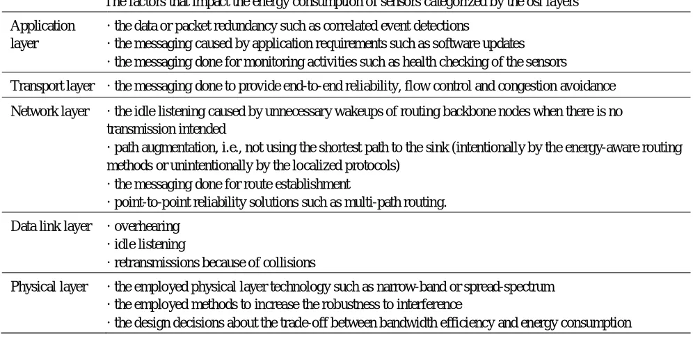
In general, the energy consumed for communication is dominant compared to that for computation or sensing activities of the sensors. Hence, the main objective in WSN research is to reduce the unnecessary communication. An efficient protocol design must reduce the amount of communication while achieving the requirements of the network. The factors that impact the energy consumption of sensors in terms of communication are shown in Table I.
One method to decrease the unnecessary energy consumption is to implement an energy-efficient configuration protocol where sensors operate under a well-defined sleep schedule. That is, inactive sensors switch to off-mode or low-power listening mode. When two nodes are to communicate, the receiver node must be awake when the sender initiates the communication which is referred as rendezvous [1]. There are three types of rendezvous schemes:
I. Demirkol, E. Onur and C. Ersoy are with the Network Research Laboratory, Department of Computer Engineering, Bogˇazic¸i
University, Bebek 34341 Istanbul, Turkey. e-mail:{ilker,onur,ersoy}@boun.edu.tr This work is supported by TUBITAK under the grant number 106E082.
1) Pure Synchronous Rendezvous: The sensor clocks are pre-synchronized such that the wake-up time of each node is known a priori. This scheme requires recurrent time synchronization that consumes considerable energy. Moreover, the sensors wake up even if there is no packet to transmit or receive which results in idle listening or overhearing.
2) Pseudo-Asynchronous Rendezvous: Source nodes wake up and produces a preamble signal that indicates the intention for data transmission. The preamble time is long enough to coincide with the wake-up schedule of the destination node. Upon waking up and sensing the preamble the destination node recognizes the intended packet transmission. In this scheme, time synchronization is not required, but sensors still follow a duty cycle and consume considerable energy with preamble signaling. 3) Pure Asynchronous Rendezvous: Sensors reside in deep sleep and can be waken up by their neighbors on demand with very
low-power wake-up receivers. Whenever a node intends to send a packet, at first it wakes up the destination node, then sends the packet. Therefore, wake-up receivers are a solution to the redundant energy consumption caused by rendezvous.
©IJRASET: All Rights are Reserved
690
II. STATE OF THE ART IN WAKE-UP RECEIVER RESEARCH
Studies on wake-up receivers consist of two parts: i) Hardware development for low-power wake-up circuitry and ii) Software development for networking protocols that utilize wake-up receivers. The wake-up receiver technologies proposed in the literature or available on the market exhibit various working principles. We present the classification tree of these wake-up receiver technologies that are applicable to both hardware and software in Fig. 1. For the hardware proposals and the products, this classification represents the features offered, whereas for the protocol studies, this tree represents the hardware features utilized.
Based on their energy sources, wake-up receiver proposals can be classified as passive wake-up receivers in which the
Power Source Wake-up Signal Type
Passive (External) Radio-based
Active (Internal) Acoustic
Wake-up Channel Destination
Specification
Identity-based Range-based Single channel
[image:2.595.49.547.216.461.2]Multiple channels
Fig. 1.Classification of wake-up receiver schemes
Wake-up circuitry is triggered by an external energy source and as active wake-up receivers in which the internal battery is used such that the wake-up receiver monitors for the possible wake-up signal. The channel that the wake-up signal is sent can either be the same with the main radio communication channel, i.e., shared channel or a separate channel can be used for the wake-up signaling. This separate wake-up channel may consists of multiple channels to be able to wake specific nodes utilizing frequency division. Although a separate channel increases the cost and the complexity of the sensor node, as indicated in [2], the penalty of channel addition is minimal, as the radio typically accounts for less than 15% of the cost of a sensor node.
Table i
The factors that impact the energy consumption of sensors categorized by the osi layers
Application layer
· the data or packet redundancy such as correlated event detections
· the messaging caused by application requirements such as software updates · the messaging done for monitoring activities such as health checking of the sensors
Transport layer · the messaging done to provide end-to-end reliability, flow control and congestion avoidance
Network layer · the idle listening caused by unnecessary wakeups of routing backbone nodes when there is no transmission intended
· path augmentation, i.e., not using the shortest path to the sink (intentionally by the energy-aware routing methods or unintentionally by the localized protocols)
· the messaging done for route establishment
· point-to-point reliability solutions such as multi-path routing.
Data link layer · overhearing · idle listening
· retransmissions because of collisions
Physical layer · the employed physical layer technology such as narrow-band or spread-spectrum · the employed methods to increase the robustness to interference
· the design decisions about the trade-off between bandwidth efficiency and energy consumption
©IJRASET: All Rights are Reserved
691
The wake-up signal can be a single wake-up tone or a bit sequence. If all the nodes that receive the tone wakes up, this scheme is referred as range-based wake-up which is appropriate for multicasting. On the other hand, the wake-up signal may consist of a bit sequence to address the destination. After reception of a wake-up signal, nodes check if the bit sequence refers to themselves. If so, the destination wakes up. This scheme is referred as identity-based wake-up and allows unicasting. [image:3.595.177.424.552.733.2]Radio signals are used as wake-up signals in radio-based wake-up receivers, or shortly wake-up radio. Alternatively,
Table II Current Consumption Values For A Wake-Up Receiver On The Market [3]
Operating ModeRegulator on,Regulator off,
VCC = 3 V VCC = 2.4 V
Sleep 0.8 µA 0.3
µA
Standby 7.0 µA 6.5
µA
Receive 7.2 µA 6.8
µA
Acoustic wake-up receivers are triggered by acoustic signals, i.e. by external sounds. When the observed level of the external sound reaches a threshold, the wake-up circuitry is activated.
A. Hardware Level Proposals
Commercialized wake-up receivers that can achieve low energy consumption by using an active wake-up receiver exist. For example, a wake-up receiver with three channels is available on the market whose simplified block diagram is shown in Fig. 2. It has three power management modes: sleep, standby and receive [3]. Table II presents the currents drawn at each mode. In the sleep mode, all channels are switched off. In the standby mode, selected channels are switched on and are ready to receive data. The amplifier of the selected channel is on, whereas the correlator is powered down as long as no input signal is detected at the input. The enabled channel switches from the standby mode to the receive mode when the input signal is detected and stays in the receive mode as long as the input signal is detected. In the receive mode, the correlator of the channel is active and scans the input signal waveform for a valid wake-up pattern. The channel goes back to the standby mode after an adjustable timeout period if no input signal is detected. An optional regulator adjusts the internal voltage to 2.4 V. The current values presented in Table II are for the case where all three channels are enabled. Further reduction can be achieved with fewer channels. This wake-up receiver is triggered with a specific bit sequence, however, the wake-up pattern is not adjustable and hence only range-based wake-up can be achieved. Hardware proposals that are based on the super-regenerative principle are also available [4], [5]. The super-regenerative
Fig. 2.Simplified block diagram for a wake-up receiver on the market [3].
Correlator
1
Correlator
2
Correlator
3 Amplifier 1
Amplifier 2
Amplifier 3
Wake
Generator
WAKE UP Signal RF Input 1
RF Input 2
©IJRASET: All Rights are Reserved
692
Receivers use a second lower frequency oscillator to provide single device circuit gains of six order of magnitude. This second oscillation periodically interrupts the main radio frequency (RF) oscillation, allowing the RF signal to be build up continuosly. Hence, they enable very low-power active wakeup receivers. An earlier work by Joehl et al. presents an implementation of a super-regenerative transceiver that consumes 3.6 mW for a receiver sensitivity of −105 dBm and the emitter current consumption is 6 mAfor a 0 dBm output power [4]. Recently, a super-regenerative transceiver that consumes 400 µW on reception and 1.6 mW on
transmission is proposed for wireless sensor networks by Otis et al. [5].
An important problem of low-power wake-up receivers is the false alarms caused by environmental noise. To overcome this difficulty, a wake-up receiver with three RF stages is proposed in [6]. A simplistic stage consuming around nW is always active. On receiving a signal, it activates a more complex stage consuming in µW to check if the received signal is a specific wake-up code.
Only if this stage confirms a valid wake-up condition, the main transceiver is activated. Specific patterns of signals are used in a shared channel for wake-up signaling.
Gu et al. propose a novel approach in which the wake-up receiver is activated by the energy of the received radio signals [7]. This type of wake-up receivers can be categorized as passive wake-up receivers since they do not require additional power. To trigger the receiver, a period of time is required to collect the adequate energy that is not negligible. The introduced wake-up delay is proven analytically to be dependent on the wake-up range, i.e., the distance to the target node [7]. For instance, 55 ms delay is needed to wake up a node that is 30 meters away. The passive wake-up circuitry is not totally battery-free, the comparators and amplifiers consume energy. Fortunately, the negligible current consumptions of the comparator and the amplifier are 350 nA and 880 nA, respectively. The wake-up signals should be sent at a special radio frequency so that the normal radio communication does not unintentionally wake up the idle part of the network. In addition, the authors present an identity-based wake-up with the help of multiple transceivers with different frequencies. The combination of frequencies are assigned to the neighbor nodes so that when a transmission is done with a set of frequencies, only the corresponding nodes wake up.
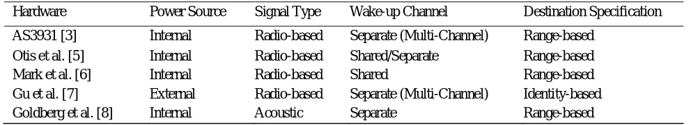
Other than the RF wake-up receivers, an acoustic wakeup receiver is proposed in [8]. The acoustic wake-up receiver consumes around 835 nW. Experiments are done with sounds generated by external devices and the level of the sound determines the wake-up range. This technology can be improved to be embedded to the sensor nodes. Xbow Mica motes are equipped with a microphone that can be used as an acoustic wake-up receiver, since a sounder also exists on these nodes. Table III categorizes hardware proposals for the wake-up receivers based on the classification given in Fig. 1.
B. Software Level Proposals
As the wake-up hardware improves and generates a promising solution for energy-efficient communication in wireless sensor networks, related communication protocols are also enhanced. In this section, these studies are overviewed based on the classification presented in Fig. 1.
1) Communication Protocols for Active Wake-up Receivers: A topology management technique that utilizes a wake-up radio is proposed in [2], namely Sparse Topology and Energy Management (STEM). The aim of the wake-up radio is to separate data communication from the preamble messaging used for the synchronization of the sender and receiver. Energy saving is achieved by introducing latency at the synchronization of the nodes via the wake-up radio. Even if the wake-up radio is not ultra-low power, energy savings can be achieved with this method. Two variants exist where in STEMB, a beacon is sent which includes the identity of the sender and the destination node whereas in STEM-T, a busy-tone is sent which wakes every node that hears the tone. STEM-B, therefore utilizes an identity-based wake-up receiver, whereas STEM-T utilizes range-based wake-up receiver.
Similarly, in [9], a wake-up receiver with duty cycle is used which utilizes preamble based synchronization between the sender and the receiver. In addition to the wake-up with preamble messaging, a triggered wake-up is also defined in which every node wakes up once at duration T. Authors try to optimize the values of T based on the given packet arrival rate with the aim of minimizing the total energy expenditure.
Since the wake-up delay increases the end-to-end delay of data packets, a number of protocols are proposed to decrease the wake-up delay incurred. Latency minimized Energy Efficient MAC protocol (LEEM) is one such protocol which is a hop-ahead reservation scheme [10]. The idea is to reserve the next hop’s channel, i.e., to wake-up the destination’s next hop in advance.
©IJRASET: All Rights are Reserved
693
Wake-up receivers can be used for collision-free MAC layer communication as utilized in [12]. Although, a routing protocol is proposed, the underlying MAC protocol is defined to send a wake-up signal on a broadcast channel. The address of the destination node is modulated with the wake-up. Access to the broadcast channel is CSMA/CA. A similar approach is applied in [13] where authors propose a MAC protocol which combines CSMA and CDMA techniques. The wake-up receiver used in [12] is identity-based whereas the one used in [13] is range-identity-based.Wake-up channel is used in [14] as a control channel where RTS/CTS like messaging and busy-till information could be exchanged. Authors compare this protocol to S-MAC and achieve nearly 66% reduction in energy consumption and 3360% better end-to-end delay values. Wake-up receiver idea is also proposed for other wireless networks. For instance, in [15], the lifetime of GSM devices is improved using a low-power control channel on WLAN. Experiment results show that the battery lifetime of these devices can be improved by 115% with this methodology. Lin et al. propose two asynchronous scheduling methods and compare their performance results with the case of utilizing wake-up radio [1]. They derive a lower bound for the energy consumption of the wake-up radio which is achieved by setting the probability that the sender node will estimate the destination node’s wake-up time within a specific time threshold to 1. A similar performance comparison between the wake-up receiver and duty-cycled radio receiver is presented in [16]. In [17], analytical bounds on the lifetime of wireless sensor networks are studied. Authors utilize a wake-up radio in such a way that when a sensor wakes up and the channel is not free, it spends the awake time by switching to a low-power wake-up radio. When the channel is free, the sensor powers up its main radio to communicate.
Song et al. utilize a range-based wake-up receiver [18] for a target tracking application on wireless sensor networks. The node that detects the target first wakes up all its neighbors to sense the target and to announce their observations.
Various proposals presented in this section assume active wake-up receivers which require internal source of energy. However, the passive wake-up receivers that obtain their main energy from the external sources are also utilized for the software proposals. 2) Communication protocols for passive wake-up receivers: Khalil et al. propose Sleep-Wake Aware Local Monitoring (SLAM)
[19] as a security mechanism for malicious nodes in which a passive wake-up receiver utilized such as the one proposed in [7]. There are guard nodes that monitor the communications and try to figure out the malacious nodes. Each node awakens the guard nodes responsible for local monitoring of its next hop before communicating with it. They show that by utilizing the wake-up receivers, the same level of security could be achieved whereas the total energy consumed is decreased by 66-90%. Table IV categorizes protocol studies that utilize wake-up receivers based on the classification given in Fig. 1.
III. BENEFITS, CHALLENGES AND TRADE-OFFS
In this section, we present the benefits achieved with the utilization of the wake-up receivers and the challenges that are observed in the wake-up receiver based WSN. These challenges should be studied carefully for the necessary solutions to be able to take advantage of the offered benefits. Moreover, the trade-offs observed in the networks with wake-up receivers are stated. Each of these trade-offs requires a detailed analysis that enables the discovery of the optimum network settings.
A. Benefits
[image:5.595.51.547.214.304.2]1) Energy-Conservation: A dominant energy waste observed in WSN applications is the idle listening which occurs because of periodical wake-ups regardless of the data communication needed. The wake-up strategy should be energy efficient [20]. The wake-up receiver presents an energy-efficient solution to the idle listening as the nodes only wake-up when there is intended message for them. Chowdhury et al. show that the energy consumption of S-MAC can be reduced significantly using wake-up receivers [14]. Since active wake-up receivers are also an energy consumption source for the sensor nodes, they should be ultra low-power to acquire the energy gain.
TABLE III
CATEGORIZATION OF WAKE-UP RECEIVER HARDWARE PROPOSALS
Hardware Power Source Signal Type Wake-up Channel Destination Specification
AS3931 [3] Internal Radio-based Separate (Multi-Channel) Range-based
Otis et al. [5] Internal Radio-based Shared/Separate Range-based
Mark et al. [6] Internal Radio-based Shared Range-based
Gu et al. [7] External Radio-based Separate (Multi-Channel) Identity-based
©IJRASET: All Rights are Reserved
694
2) Minimum Overhead: As the wake-up receiver presents purely asynchronous rendezvous scheme, the overhead incurred by thetime synchronization of the two other rendezvous schemes are dissipated. This overhead causes higher energy consumption as shown by [1] and [16]. The communication overhead to form the routing backbone also becomes redundant as each node wakes up its relay. For instance, Dhanaraj et al. propose a method where a destination node first wakes up its relay before receiving the data intended for it [10]. In addition, instead of having clusters with regular duty cycles, formation of clusters can be done only with the event occurrences.
3) Different form of Use: For efficient use of the WSN for a target application, wake-up receiver technology enables various new methods such as the on-demand target monitoring method proposed in [18] where the node that detects a target wakes up all its
neighbors to receive their observations about the target. Section
IV presents application areas of the wake-up receiver technology.
4) Dynamic Behavior: System-wide parameters create inefficiencies as the network load differs based on the location. Hence, parameters such as the duty cycle, the preamble length should be dynamically set based on the localized requirements. Since wake-up receiver enables dynamic duty cycling and dynamic communication rendezvous, several inefficient parameter definitions become unnecessary that result in a more efficient network as shown by [1] and [16].
5) Overhearing is Decreased: With the help of identitybased wake-up receivers, overhearing is reduced since only the destined nodes will wake up and listen the medium as in [2] and [15].
B. Challenges
1) Cost and Hardware Complexity: If the wake-up radio utilizes separate channel(s), then the hardware complexity and the cost of the sensor nodes will increase. This is especially important when multiple wake-up channels are employed as in [3] and [7]. However, as indicated in [2], the radio typically accounts for less than 15% of the cost of a sensor node.
2) Delay: With the passive wake-up radio, such as the one proposed in [7], wake-up delay is incurred which may become significant for the requirements of the application. The impact of the end-to-end delay may be significant, when the number of hops to the sink is large. For applications such as target tracking, point-to-point (one-hop) delay is critical for the performance of the application.
[image:6.595.45.538.252.411.2]3) Topology Change: Since the wake-up range may not be the same as the communication range of the main radio, topology for the wake-up receivers can be different than the actual network topology. The neighborhoods achieved with wake-up receivers, hence, result in a different topology than the original network topology. The former may result in a disconnected network, although the latter is connected. In such circumstances, the problem should be realized by the protocols and necessary solutions should be applied. In addition, even if the wake-up receivers form a connected network, the number of hops on the routing path may increase if the wake-up range is less than the communication range which can cause inefficient routing of the packets. Unfortunately, there is no work in the literature yet that investigates the effect of separate topology caused by the wake-up receivers.
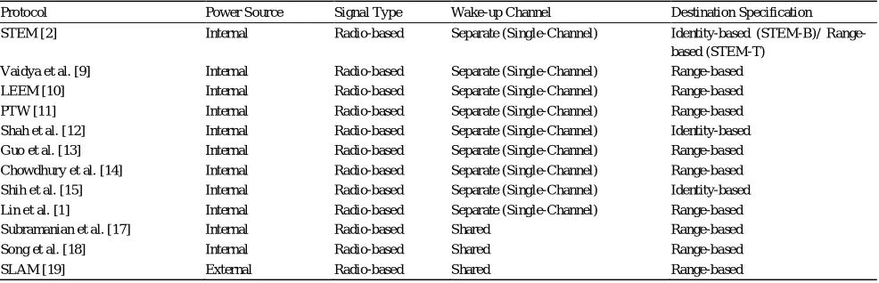
TABLE IV
Categorization Of Wake-Up Receiver Based Protocol Research
Protocol Power Source Signal Type Wake-up Channel Destination Specification
STEM [2] Internal Radio-based Separate (Single-Channel) Identity-based (STEM-B)/
Range-based (STEM-T)
Vaidya et al. [9] Internal Radio-based Separate (Single-Channel) Range-based
LEEM [10] Internal Radio-based Separate (Single-Channel) Range-based
PTW [11] Internal Radio-based Separate (Single-Channel) Range-based
Shah et al. [12] Internal Radio-based Separate (Single-Channel) Identity-based
Guo et al. [13] Internal Radio-based Separate (Single-Channel) Range-based
Chowdhury et al. [14] Internal Radio-based Separate (Single-Channel) Range-based
Shih et al. [15] Internal Radio-based Separate (Single-Channel) Identity-based
Lin et al. [1] Internal Radio-based Separate (Single-Channel) Range-based
Subramanian et al. [17] Internal Radio-based Shared Range-based
Song et al. [18] Internal Radio-based Shared Range-based
©IJRASET: All Rights are Reserved
695
4) Energy Hole Problem: Ahmed et al. define the hole problem as the result of some anomalies in the wireless sensor networksthat impair the functionality of the network [21]. Specifically, the coverage hole is defined as the area not covered by any sensor, due to the anomalies such as random deployment creating voids, node failures, or jamming. If the wake-up range is smaller than the communication range of the main radio, the topology of the network formed by the wake-up receivers may contain more or larger energy holes. This may result in inefficient network utilization, for instance to pass over the larger energy holes requires more data communication and hence more energy.
5) Overhearing Increases For The Shared Channel And Range-Based Wake Up Receivers: For range-based wakeup schemes, all the nodes hearing the tone switch to the active state. Since all surrounding nodes will wakeup at each transmission, overhearing can be increased compared to other protocols. To prevent the overhearing, identity-based wake-up receivers can be used as in [2] and [15].
C. Trade-offs
The following offs are expected in the networks where wake-up receivers are used. Although the quantification of these trade-offs require detailed performance evaluation studies, no work on this topic has appeared in the literature yet.
1) Wake-Up Range Versus Energy Consumption: As the density of the sensor deployment increases, the distances among sensors become shorter. For dense deployments, multi-hop wake-up may be possible. In the multi-hop wake-up scheme, a sensor node triggers a node that is several hops apart in the communication (routing) graph. For sparse deployments, the wake-up range affects the energy consumption. The range for the wake-up radio can be adjusted with the energy consumption trade-off. Distant sensors can be awaken by consuming more energy. Determining the efficient wake-up distance depends on the design decisions such as the applied routing strategy.
2) Wake-Up Range Versus Delay: Multi-hop communication is common in WSNs. Hence, the end-to-end reporting delay becomes a critical metric for the performance evaluation. Increasing the wake-up range, decreases the overall hop count which in turn decreases the delay.
3) In-Band or Out-Of-Band Wake-Up Radio: The same channel(s) as that of the communication stack can be used for the wake-up radio. This reduces the implementation costs but has lower resistance to jamming attacks to the communication stack and increases the probability of collision. If separate channels are utilized the costs increase, however, resistance to jamming attacks increases and the energy consumption due to overhearing decreases.
IV. APPLICATION AREAS
When the WSNs are categorized according to the mode of data collection, two main approaches are studied in the literature. These are event-driven and periodic (or query-based) data collection. In this section, we present how the wake-up radio can be used for these application categories.
A. Event-Driven Applications
In this category, sensors inform the sink about their decisions when a specific event occurs. Typical examples are the forest fire detection system, sniper localization or the surveillance system whose duty is intrusion detection, target tracking or perimeter protection in scenarios such as border monitoring against penetration by hostile elements. The events in a WSN application can be spatiotemporally correlated. For example, in a surveillance application, if a sensor detects a target, it is highly probable that another sensor at about the same distance will also detect the same target. Furthermore, these detections will occur in about the same period of time. Due to the redundant deployment, the impact of the spatial and temporal correlations can be very influential on the energy consumption. Instead of centralized decision fusion, a local subset of sensors may collaborate to decide on the event using data/information fusion techniques. If the sensors are equipped with wake-up circuitry, a dynamic clustering mechanism can be viable instead of assigning sensors to clusters prior to the network operation. Sensors that are spatially co-located with the event can form a cluster dynamically. This scheme may not only yield better accuracy, but also consumes less energy.
©IJRASET: All Rights are Reserved
696
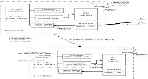
surveillance applications, the frontier sensors may invoke some set of valuable or costly sensors behind the perimeter to produce a barrier to reduce the false alarms. This scheme suggests a layered topology where overlays are probable. The interaction of the wake-up receivers with the sensor node and with the network for a simple event driven application is shown in Fig 3 based on a target detection scenario. The identity based wake-up scheme enables pointto-point communication. While waking up the neighbors, it is possible to communicate some valuable information. In the surveillance scenario shown in Fig 3, the sensor that detects a target may communicate the type of the target (e.g., a soldier or an armored military vehicle) which helps the awaken sensor decide on which sensing circuitry to activate. Such an application is reasonable if the sensing circuitry consumes comparable energy to the radio subsystem. For example, micro impulse radar sensors spend a couple of orders higher energy compared to the passive infrared sensors. In this scenario, when the first sensor detects the target, its sensing circuitry triggers the wake-up receiver. First, a burst of signal is sent to the next hop (second sensor) to trigger the first stage of the wake-up receiver. Afterwards, the identity of the second sensor and the target type are sent. The second stage of the wake-up receiver of the second sensor turns on the main radio if the sent identity matches itself. Then, the main radios can communicate and the second sensor may turn on the neccessary sensing circuitry based on the type of the target. A similar scenario can be devised to consider the preservation of the sensing coverage in case of sensor failures using the redundancy of the deployment. Assume that each sensor is assigned one or more stand-by buddy sensors. When the battery level of the active sensor drops below a certain threshold, it can wake up one of its buddies to monitor the region. Two or more sensors that monitor almost the same area can be matched to act as the back-up. These scheme increases the high-availability of the surveillance network through activestandby operation. A similar scenario is presented in [20]. In an event-driven application, depending on the rate of the events, utilization of the wake-up technology may become useless. If the events occur frequently, some set of sensors have to sleep and wake up frequently. Hence, for such scenarios switching to periodic sleep scheduling is wiser. An example scenario can be the surveillance application of museums. Consider visitors of a historic arena. The objective of the WSN is to detect the visitors whom are trying to enter unallowed parts of the arena. During the open hours of the museum, the rate of the events may be larger compared to the night shifts. Daytime operation of the network can be based on periodic sleep scheduling, whereas the night time operation can follow the wake-up scheme. Rigorous analysis of when to switch from wake-up scheme to sleep scheduling is required when such bimodal operation is probable.©IJRASET: All Rights are Reserved
697
B. Periodic or Query-based ApplicationsPeriodic or query based data collection is common when environmental properties such as temperature or humidity levels of a field are to be monitored. For such applications, the wake-up circuitry may be utilized to avoid the time synchronization requirement. Instead of scheduled operation, a single sensor can manage the timing and when the data is to be collected, it initiates the communication by waking up the neighbors. Hence, an individual sensor may create a dynamic data flooding scheme where the data can be aggregated by the awaken sensors only. For example, the maximum value of temperature readings can be calculated as the data flows to the sink through the dynamically determined route to the sink. Based on the residual energy levels of individual sensors, the sensors may reject to wake up. If a handshaking protocol is utilized for the wake-up stage, the sensors may dynamically alter their route based on their impacts on the neighbors. For example, during the handshaking process, the residual energy levels can be exchanged to minimize the effect of the energy consumption for the relay functionality.
Assume that a WSN is deployed to monitor the depletion of minerals in the soil where several types of crops are cultivated. The farmer requires the average level of mineral ratios from a portion of the field where only a type of crop is nurtured. To obtain this information, the WSN must be queried based on the location of sensors. This type of sensor networks can be regarded as a distributed database. For such applications, the dissemination of the queries requires intelligent routing techniques where the wake-up circuitry can be used. For example, in this farming scenario, the sensors which are located in the region of interest can be awaken. The medium access layers can be coordinated during the wake-up stage to avoid collisions during communication. Some packet transmission schedule for the specific event can be delivered to the surrounding nodes within the wake-up code. For example, SMAC can be modified to distribute the schedules when an event is detected. This minimizes the energy consumption for duty scheduling.
V. CONCLUSION
The wake-up receiver technology presents a promising solution for the energy-efficient rendezvous between the sensor nodes. In this paper, a classification scheme is presented for the wake-up receiver studies. The state-of-the-art wake-up receiver hardware and networking protocol proposals are investigated based on this classification scheme. The benefits of the wakeup receiver use is presented along with the challenges that has to be solved for its successful operation. In the systems with wake-up receivers, a number of trade-offs are observed that has to be addressed for efficient network operation. These tradeoffs are also listed and discussed. The new WSN application possibilities that are made available with this new technology are presented.
REFERENCES
[1] E. Y. A. Lin, J. M. Rabaey, and A. Wolisz, “Power-efficient rendezvous schemes for dense wireless sensor networks,” in Proc. IEEE ICC, vol. 7, Jun. 2004, pp.
3769–3776.
[2] C. Schurgers, V. Tsiatsis, S. Ganeriwal, and M. Srivastava, “Optimizing sensor networks in the energy-latency-density design space,” IEEE Transactions on Mobile Computing, vol. 1, no. 1, pp. 70–80, Jan./Mar. 2002.
[3] 3D Low Power Wakeup Receiver-AS3931, Austria Microsystems, 2008. [Online]. Available: http://www.austriamicrosystems.com/eng/content/ view/full/544
[4] N. Joehl, P. Dehollain, P. Favre, P. Deval, and M. Declerq, “A low-power 1-GHz super-regenerative transceiver with time-shared PLL control,” IEEE Journal
of Solid-State Circuits, vol. 36, no. 7, pp. 1025–1031, Jul. 2001.
[5] B. Otis, Y. H. Chee, and J. Rabaey, “A 400µW-RX 1.6mW-TX super-regenerative transceiver for wireless sensor networks,” in IEEE International Solid-State
Circuits Conference, ISSCC’05, Feb. 2005, pp. 396–7,606.
[6] S. von der Mark, R. Kamp, M. Huber, and G. Boeck, “Three stage wakeup scheme for sensor networks,” in SBMO/IEEE MTT-S International Conference on
Microwave and Optoelectronics, Jul. 2005, pp. 205–208.
[7] L. Gu and J. A. Stankovic, “Radio-triggered wake-up for wireless sensor networks,” Real-Time Syst., vol. 29, no. 2-3, pp. 157–182, 2005.
[8] D. H. Goldberg, A. G. Andreou, P. Julia´n, P. O. Pouliquen, L. Riddle, and R. Rosasco, “Vlsi implementation of an energy-aware wake-up detector for an acoustic surveillance sensor network,” ACM Trans. Sen. Netw., vol. 2, no. 4, pp. 594–611, 2006.
[9] M. J. Miller and N. H. Vaidya, “A mac protocol to reduce sensor network energy consumption using a wakeup radio,” IEEE Trans. Mobile Comput., vol. 4, no.
3, pp. 228–242, May/Jun. 2005.
[10] M. Dhanaraj, B. S. Manoj, and C. S. R. Murthy, “A new energy efficient protocol for minimizing multi-hop latency in wireless sensor networks,” in PERCOM
’05: Proceedings of the Third IEEE International Conference on Pervasive Computing and Communications, Washington, DC, USA, 2005, pp. 117–126.
[11] X. Yang and N. H.Vaidya, “A wakeup scheme for sensor networks: Achieving balance between energy saving and end-to-end delay,” in
RTAS ’04: Proceedings of the 10th IEEE Real-Time and Embedded Technology and Applications Symposium (RTAS’04), May 2004, pp. 19– 26.
[12] R. C. Shah and J. M. Rabaey, “Energy aware routing for low energy ad hoc sensor networks,” in Proc. IEEE WCNC, vol. 1, Mar. 2002, pp. 350–355.
[13] C. Guo, L. C. Zhong, and J. Rabaey, “Low power distributed mac for ad hoc sensor radio networks,” in Proc. IEEE GLOBECOM, vol. 5, San Antonio, TX,
USA, Nov. 2001, pp. 2944–2948.
[14] K. Chowdhury, N. Nandiraju, D. Cavalcanti, and D. Agrawal, “CMAC - A multi-channel energy efficient MAC for wireless sensor networks,” in Proc. IEEE
©IJRASET: All Rights are Reserved
698
[15] E. Shih, P. Bahl, and M. J. Sinclair, “Wake on wireless:: an event driven energy saving strategy for battery operated devices,” in Proc. ACM MobiCom, Sep.2002, pp. 160–171.
[16] L. Zhong, J. M. Rabaey, and A. Wolisz, “An integrated data-link energy model for wireless sensor networks,” in Proc. IEEE ICC, vol. 7, Jun. 2004, pp. 3777–
3783.
[17] R. Subramanian and F. Fekri, “Sleep scheduling and lifetime maximization in sensor networks: fundamental limits and optimal solutions,” in IPSN ’06: Proceedings of the fifth international conference on Information processing in sensor networks, Apr. 2006, pp. 218–225.
[18] L. Song and D. Hatzinakos, “A cross-layer architecture of wireless sensor networks for target tracking,” IEEE/ACM Trans. Netw., vol. 15, no. 1, pp. 145–158,
Feb. 2007.
[19] I. Khalil, S. Bagchi, and N. B. Shroff, “Slam: Sleep-wake aware local monitoring in sensor networks,” in Proceedings of the 37th Annual IEEE/IFIP International Conference on Dependable Systems and Networks, DSN ’07, 2007, pp. 565–574.
[20] A. Boukerche, X. Fei, and R. B. Araujo, “An optimal coveragepreserving scheme for wireless sensor networks based on local information exchange,” Computer Commununications, vol. 30, no. 14-15, pp. 2708–2720, 2007.
[21] N. Ahmed, S. S. Kanhere, and S. Jha, “The holes problem in wireless sensor networks: a survey,” Mobile Computing and Communications Review, vol. 9, no.
![Table II Current Consumption Values For A Wake-Up Receiver On The Market [3]](https://thumb-us.123doks.com/thumbv2/123dok_us/1244010.650649/3.595.177.424.552.733/table-ii-current-consumption-values-wake-receiver-market.webp)