warwick.ac.uk/lib-publications
A Thesis Submitted for the Degree of PhD at the University of Warwick
Permanent WRAP URL:
http://wrap.warwick.ac.uk/88012
Copyright and reuse:
This thesis is made available online and is protected by original copyright. Please scroll down to view the document itself.
Please refer to the repository record for this item for information to help you to cite it. Our policy information is available from the repository home page.
Functionalised Azamacrocycles
Andrew. C. Benniston BSc (Hons)
A thesis submitted for
the degree of
Doctor of Philosophy
Department of Chemistry
University of Warwick
THE LIBRARY
UNIVERSITY OF WARWICK
COVENTRY
AUTHOR TITLE
Postal Code CV4 7AL Telephone 523523 Telex 31406
.!~-~.Q«
.
.eW:. C:. .
BfNNls:ro~.
. .... ..
DEGREE •••P.~D
... .
...
f.~~ ,"'1\l)NI.\LI~Ei:l
...
1.17;(\
HA..CR9.<:-Y.(h~
... .
...
••••••• •••••••••••••••••• •••••••••• •••••••• DATE OF DEPOSIT ••
j.o./~/90
I agree that this thesis shall be available in accordance with the regulations governing the University of Warwick theses.
I agree that the summary of this thesis may be submitted for publication.
I agree that the thesis may be photocopied (single copies for study purposes only) YES ~
Theses with no restriction on photocopying will also be made available to the British Library for microfilming. The British Library may supply copies to individuals or libraries. subject to a statement from them that the copy is supplied for non publishing purposes. All copies supplied by the British Library will carry the following statement.
"Attention is drawn to the fact that the copyright of this thesis rests with its author.
This copy of the thesis has been supplied on condition that anyone who consults it is understood to recognise that its copyright rests with its author and that no quotation from the thesis and no information derived from it may be published without the author's written consent."
Author's Signature
• • • • • • • • • • • • • • • • • • • • • • • • • • • • • • • • • • • • • • • • • • • • • • • • • • • • • • • • • It.~'l.r.eC'·' • • • " i I • • • • • • • • • • • •
USER'S DECLARATION
(i) I undertake not to quote or make use of any information from this thesis without making acknowledgement to the author.
(ii) I further undertake to allow no-one else to use this thesis while it is in my care.
To my Mom and Dad,
brother Mike,
and sister Jo
., ~ .
In the last analysis magic, religion and science
are nothing but theories of thought; and as science
has supplanted its predecessors, so it may hereafter
be itself superseded by some more perfect hypothesis
perhaps by some totally different way of looking at the
phenomina- of registering the shadows on the screen- of
which we in this generation can form no idea
Sir James Frazer, O.M
Table of Contents
Table of contents
List of Tables
Acknowledgements
Declaration
Summary
Macrocycles discussed in this thesis
Abbreviations
Chapter I-Introduction
Section 1.1 Macrocyc1es( General)
Section 2.1 Cation Selectivity and Complex Stability(General)
Section 3.1 Macrocyc1ic Compounds(Thermodynamics)
Section 4.1 Macrocyc1ic Effect
SectionS.1 Synthesis of Macrocycles(General)
Section 6.1 Functionalised Macrocycles
Section 7.1 Redox Active Macrocycles
Section 8.1 Cyclic Voltammetry
Chapter 2-The synthesis and study of redox active macrocycles
based on 1,4,8,11-tetraazacyclotetradecane( cyclam).
Section 1.2 Introduction
Section 2.2 Synthesis and Electrochemistry of Ll
Section 3.2 Electrochemistry of Ll
Section 4.2 Synthesis and Electrochemistry of L2
SectionS.2 Crystal structure of L2
Section 6.2 Electrochemistry of L2
Section 7.2 Synthesis and Electrochemistry of L3 .HCI and L3
Section 8.2 Synthesis of La .HCI and La
Section 9.2 Crystal structure of La .HCI
Section 10.2 Conclusions tb Syntheses
Section 11.2 Crystal structure of 2.Lb.Fe2 OCl 6
Section 12.2 Electrochemistry of L3 .HCI and L3
Section 13.2 Conclusions
Section 14.2 Experimental
Section 15.2 Crystallography
Chapter 3-The synthesis and electrochemistry of further
redox active macrocyc1es
Section 1.3 Introduction
Section 2.3 Synthesis of L 4
Section 3.3 Metal complexes of L4
Section 4.3 Electrochemistry of L 4
Section 5.3 Electrochemistry of metal complexes of L 4
Section 6.3 The synthesis of L5
Section 7.3 Electrochemistry of L5
Section 8.3 Conclusions
Section 9.3 Experimental
Chapter 4-The synthesis and study of two pyrrolidinyl
pendant arm triazamacrocyc1es
Section 1.4 Introduction
Section 2.4 The synthesis of L6 and L7
Section 3.4 Metal complexes of L6 and L7 (General)
Section 4.4 Synthesis of zinc(II) and copper(II) complexes of L6
Section 5.4 Synthesis of nickel(II) and cobalt(III) complexes of L6
Section 6.4 Synthesis of zinc(II), copper(II), cobalt(II) and
cobalt(III) complexes of L7
Section 7.4 Attempted synthesis of a nickel(II) complex of L1
Section 8.4 Crystal structures of [Zn(L6 )(OCIOs )]
+
and [Zn(L1))2+
Section 9.4 Attempted functionalisation of L6
Section 10.4 Conclusions
Section 11.4 Experimental
Section 12.4 Synthesis of metal complexes of L6 and L1
Section 13.4 Crystallography
Chapter 5 The synthesis of two tetra-N-substituted derivatives of
1,4,8,U-tetraazacyclotetradecane(cyclam), and their
nickel (II) complexes.
Section 1.5 Introduction
Section 2.5 Synthesis of L8 and L9 .
Section 3.5 Nickel(II) complexes of L8
Section 4.5 Crystal structure of [Ni(L8 )(NCS)2]
Section 5.5 Thermodynamic and Kinetic studies of
[Ni(L8))2
+
in acetonitrile:Section 6.5 Nickel(II) complexes of L9 .
Section 7.5 Conclusions
Section 8.5 Experimental
Section 9.5 Crystallography
Chapter 6 Future work and Conclusions
Section 1.6 Redox active macrocycles
Section 2.6 Functionalised Triazamacrocycles
Section 3.6 Tetra-N-alkylated macrocycles
Chapter 7 Experimental
Section 1. 7 Experimental techniques and instrumentation
Section 2.7 Electrochemical Techniques
Section 3. 7 Conductivity experiments
page
Section 4.7 Magnetic Susceptibility measurements
203
Section 5.7 Atomic Absorption Spectrophotometry.
204
Section 6.7 Solvent exchange by n.m.r line broadening
204
References
206
Appendix I Atomic co-ordinates, Bond lengths and angles
215
Appendix II Coulometric Titration for L2
229
List of Tables
Chapter 1
Table 1.1- Thermodynamics of complex formation 5
Table 2.1- Strain energy of some macrocycles 8
Table 3.1-Thermodynamic data for some macrocycles 16
Table 4.1-Diagnostic tests for reversible electrochemistry 33
Table 5.1-Diagnostic tests for quasi reversible electrochemistry 34
Table 6.1-Diagnostic tests for irreversible electrochemistry 34
Chapter 2
Table 6.2- Selected bond lengths and angles for L2 53
Table 7.2- Selected bond lengths and angles of L3 .HCI 63
Table 8.2- Bond lengths and angles of 2Lb.Fe 2 OCle 66 Table 1.2- 1 H n.m.r data in CDCl 3 (ref Me. Si cS = 0) 73 Table 2.2- 1 H decoupled 13 C n.m.r data in CDCl3 (ref Me. Si S = 0) 74
Table 3.2- Combustion analysis results 76
Table 4.2- Crystal data for L2, L3 .HCI and 2Lb.Fe 2 OCle 77
Table 5.2- Mass spectral data 78
Chapter 3
Table 1.3- 1 H decoupled 1 3 C n.m.r data 110
Table 2.3- Combustion analysis results 111
Table 3.3- Mass Spectral data 112
Table 4.3- Spectroscopic data 113
Chapter 4
Table 6.4- Bond lengths and angles for [Zn(Le )(OCL0 3 )](CIO.) 137 Table 7.4- Bond lengths and angles for [Zn(L7 )](CIO.)2 138
Table 1.4- 1 H decoupled 13 C n.m.r data in CDCl 3 (ref Me. Si S
=
0) 142Table 2.4- Spectroscopic data 143
Table 3.4- Combustion analysis results 144
Table 5.4- Crystal data for [Zn(L6 )(OCLOs )](CI04)
, and [Zn(L1 )](CIO 4)2 146
ChapterS
Table 6.5- Selected crystal data for [Ni(TMC))2
+
and [Ni(LS )(NCS)21 172Table 8.5-Bond lengths and angles for [Ni(LS )(NCS)2 ] 177
Table 7.5- Thermodynamic and Kinetic data for[Ni(LS )(NCS) 2]
in acetonitrile 178
Table 1.5-1 H decoupled 13 C n.m.r data in CDCI
s (ref Me 4 Si
s
=
0) 187 [image:11.501.55.490.197.775.2]Table 2.5- Combustion analysis results 188
Table 3.5- Spectroscopic data 189
Table 4.5- Mass spectral data 190
Table 5.5- Crystal data for [Ni(LS )(NCS)2 ] 191
Acknowledgments
This page should be as long as my whole thesis, as I have come in contact
with so many people over my six years at Warwick, both as an undergraduate and
a postgraduate. However I would like to personally thank all of the following
people:-Dr Peter Moore for all his academic help, and also allowing me to use his laser
printer to obtain this thesis.
All the macrocyclic group over the past four years- Dr.H.A.A.Omar,
Dr.C.J."Jimbo" Reader, Dr.S.C.Rawle, Dr.F.McLaren, Dr.A.Wynn, and Simon
Grant, Dr.N.S.Gosal, and Dr.L.Chung
Peter Wong for some excellent n.m.r work in his 3rd year project.
The X-ray crystallography department- especially Dr.N.W.Alcock for allowing me
to have a "bash" on the diffractometer, and Dr.M.Roe for a excellent piece of
crystal cutting on some twinned samples.
The electrochemistry group- Dr.P.N.Bartlett for his expertise. The following of
whom I'm grateful for the use of their equipment; Dr.R.G.Whitaker, Jon
"Glad-stone" Farrington, Vanessa "Ness" Eastwick-Field.
The department- Inder Katal for all the mass spectra. Dr O.W.Howarth, Jeremy
and Jag for 400MHz spectra. Eric Burgess for his humour, and the mending of
broken glassware.
Myoid chemistry teacher Dr.J.Per~ott, and his excellent teaching, of
which I am eternally grateful.
All the postgraduates and undergraduates whom I've known over the past six
years, which are far to many to mention, but not forgotten.
Dr Alicia Dachs for endless discussions on synthesis, and "friendship".
Phillip a Cross for checking the English and spelling in this thesis.
Dr.A.F.Hill for the use of his computer for the drawing of diagrams.
Jag for proof reading this thesis.
Declaration
The work submitted in this thesis is my own work and was carried out in the
University of Warwick's Chemistry Department. The kinetic and thermodynamic
data obtained in Chapter 5 (Table 7.5) was obtained by a joint collaboration with
Mr.P.Wong, whilst under my supervision on his 3rd year project.
A.C.Benniston (BSc)
Summary
Potential uses of functionalised azamacrocycles have been investigated. Nine new azamacrocyclic ligands have been s)'!lthesised and characterised, some containing redox active centres, and these are Identified on the following page.
In Chapter 2 a series of redox active macrocycles Ll , L2 and L3, incorpo-rating ferrocene as the redox active centre have been synthesised, based on the parent macrocycle 1,4,8,1l-tetraazacyclotetradecane (cyclam), and been investi-gated. Their potential as transition metal ion sensors has been studied. The ligand Ll shows irreversible electrochemistry in acetonitrile solution, with no reverse peak being observed in the cyclic voltammogram. However, on addition of Zn 2 T the system becomes reversible as shown by the reappearance of the reverse peak. The crystal structure of L2 reveals that the nitro~en atoms are not in suitable positions for chelation, in line with the observatIOn that no metal complexes could be made of this macrocycle. The electrochemistry of L2 shows a single four electron cyclic voltammogram and there is no change on addition of transition metal ions. The ligand L3 does show a significant shift in the Elfl value for the ferrocene/ferrocenium couple on addition of transition metal ions.
In Chapter 3 studies of two macrocycles (L4 and L6) containing the "redox active centre as part of the macrocyclic ring itself are described. In the case of L 4 ferrocene was used, but owing to problems with the electrochemistry, it was not a good transition metal ion sensor. Metal complexes of this macrocycle were s)'nthesised and are of the general formula [ML4 ](CR3 COO)2 .xR 2 0,
t
M = Zn 2+
,x = 2.5, Ni 2+
,x = 4, Cu 2+
,x = 3}. A more promising metal ion sensor was the cobalticenium macrocycle L6 and this shows very large shifts in the half wave potential, on the addition of transition metal ions like Zn 2+
and Ni 2+.
Problems with obtaining very pure samples at the moment hinder its useful application as a transition metal ion sensor.In Chapter 4, two pyrrolidinyl pendant arm triazamacrocycles are dis-cussed L6 and L7, together with some of their transition metal complexes. Two crystal structures have been undertaken of the zinc(II) complexes of L6 and L7. A change in geometry from a trigonal bipyramid to a tetrahedron is brought about by an increase in length of the pendant arm in going from L6 to L7.
In Chapter 5, a general route to N-alkylated macro cycles is described. Two new tetra-N-alkylated derivatives of cyclam (L8 and L9) have been synthe-sised, and their nickel(II) complexes studied. These metal complexes have been compared to the nickel(II) complexes of
Macrocycles discussed in this thesis
~ .c-~ N N JI-~ ~
~
~Url~
Me Me
Q
Q
C>
e?)
e
5
)
<;"Bz
eN)
HNVH
HN0H
IV'
Bz BzL6 JJ La
~NEtl
Abbreviations
A TP: Adenosine triphosphate A.R: Analytical reagent br: Broad
c.p: Cyclopentadiene C.I: Chemical ionisation 1 3 C: Carbon 13 n.m.r C: Coulombs
DMSO: Dimethylsulphoxide DMF: Dimethylformamide d: Doublet
E.I: Electron impact ionisation E1fz: Half wave potential
F.A.B: Fast atom bombardment Fc: Ferrocene
F.T: Fourier transform 1 H: Proton n.m.r
i:
Current I.r: Infraredlit: Literature value mer: Meridional
n.m.r: Nuclear magnetic resonance mV: Millivolts
m Vis: Millivolts per second Me f ~i: Tetramethylsilane M: Molar
mmol: Millimoles m.p: Melting point phen: Phenanthroline ppm: Parts per million q: Quartet
S.C.E: Standard calomel electrode s: Singlet
THF: Tetrahydrofuran t: Triplet
Tosyl: p-Toluenesulphonyl chloride
TEATFB: Tetraethylammonium Tetrafluoroborate TBAHFP: Tetrabutylammonium Hexafluorophosphate TBATFB: Tetrabutylammonium Tetrafluoroborate U.V: Ultraviolet
V: Volts "
J.lA: Microamps
).: Wavelength
E : Extinction Coefficient v: Frequency
o :
Chemical shiftLigand Abbreviations
18-crown-6 Pen tag lyme
-2OC,
1 \
r
C02-N N
-2OC--1 ' -
COz-EDTA
H~H
[ : NNJ
Hz Hz
2.3.2. tet
H~H
c:
H2:=>
H23.2.3. tet
Dicyclohexyl-18-crown-6
H I I H
[: :J
H2 H22.2.2. tet
En
H n H
C: :J
H2 H2Introduction
Section 1.1
Macrocycles (General)
The field of macrocyclic ligand chemistry has grown over the past thirty
years to a point where it is now a integral part of inorganic chemistry, the
crowning glory being the award of the Nobel prize in 1987, to Cram, Pedersen,
and Lehn.1
This thesis will show some of the different areas in which macrocycles can
be utilised, especially in the field of co-ordination chemistry and chemical
sensors. There have been a number of excellent review articles on the early work
on macrocycles,2 so only a brief summary will be given here.
Two early syntheses of a macro cycle were carried out in the early 1960s by
Curtis,3 and independently by Busch and Thompson4 (Scheme 1.1).
The birth of this new field of inorganic chemistry led to a rapid growth in
the 1960s, which has continued up until the present day with the synthesis of more
elaborate macrocyc1es such as the catenands by Sauvage5 and kohnkene by
Stod-dart6 (Figure 1.1) .
...--0;-<"0---...
°
I '\
°
("
")
° °
O'-o~o---O
A Catenand Kohnkene
Figure 1.1
With this growth in macrocyclic chemistry, there came a series of
interesting questions. Why were the macrocycles more stable than their open
chain analogues? Could these macrocycles be selective towards metal ions, and if
so what factors were the most important (e.g. ring size, type of donor atom,
sol-vent effects)?
These questions have been partially answered, but uncertainties remain.
The observed properties of macrocycles have led to a number of applications.
For example, recently Lehn 1 has used a polyammonium macrocycle as a
supra-molecular catalyst in the phosphoryl transfer in A TP hydrolysis. Beer et al. have
used the selective binding of crown ethers in the sensing of alkali and alkaline
earth metals 8 , as well as cobalticenium macro cycles for the detection of anions. 9
Parker, 1 0 has also been using functionalised macrocycles in anti-body labelling,
.
for possible tumour imaging and radioimmotherapy.
-2-Section 2.1
Cation selectivity and complex stability
There are a number of factors which influence the stability of macro cyclic
complexes,l 1 these are
:-1: Type of binding sites in the ring.
2: Number of binding sites.
3: Relative size of ion and macro cyclic cavity.
4: Physical placement of the binding sites.
5: Steric hindrance in the ring.
6: Solvent, and the extent of solvation of the ion binding sites.
7: Charge of the ion.
Probably the most studied relationship has been that between the
macrocyclic ring size (hole) and the size of the cation. This has been carried out
for donor atom systems and varying ring size. Recently molecular mechanics has
played an important part in gaining insights into such aspects as metal ion
selectivity, and macrocyclic ligand design. The use of molecular mechanics has
Molecular Mechanics Calculations
A bond is assumed to have an ideal length (rO
) which is distorted by strain
to its observed length (r). The strain produced (VB) is given by Hooke's law (1)
VB = 1/2.KB·(rO-r)2 - (1).
KB = the force constant for a particular bond.
The strain induced by angle deformation (V 0) is also given by Hooke's
law, Equation(2).
Vo = 1/2·Ke·(90- 9)2 - (2).
9
°
= ideal bond angle, 9 = observed angleAnother form of strain energy is torsional strain (V <p), given by the
expression (3).
V<P = V/2.[1
+
cos(n.<p )]- (3).<p = torsional angle, V = constant for particular atoms.
The most important strain energy contribution is that of the forces
between atoms that are not bonded to each other (VNB ). Equation (4). VNB =A.e-(B.r)-C/r6 - (4).
A,B,C are constants, r = internuclear separation.
The order of importance of these forces are: non-bonded repulsive forces
>
bond length deformation forces>
bond angle deformation ~ torsional forces>
non-bonded attractive forces.To analyse the role of stratn energy in complex formation, the increase in
strain energy that occurs when a free ligand is complexed is considered.
M
+
n.L--- MLn
t. V.VMLn
-4-Metal Chelates
The use of molecular mechanics has revealed a number of properties for
metal chelates.
1: Small metal ions with M-N bond lengths close to 1.6
A.
will co-ordinate with the least steric strain to six membered chelates.2: Large metal ions will co-ordinate with least steric strain to five
membered rings.
The true test of such convictions is to compare thermodynamic parameters
relating complex stability to chelate ring size (Table 1.1).1 2
Thermodynamics of Complex Formation of edta (Five Membered Chelate Ring) Compared to tmdta (Six Membered Chelate Ring)
Melal Ionic Edta tmdta
Ion Radius log K, flH flS log K, flH flS
CUI' 0.57 18.70 -8.2 58 18.82 -7.7 60
Nil' 0.69 18.52 -7.6 59 18.07 -6.7 60
Zn!' 0.74 16.44 -4.9 59 15.23 -2.3 62
Cd!> 0.95 16.36 -9.1 44 13.83 -5.4 45
Cal' l.00 10.61 -6.6 26 7.26 -1.7 27
La" 1.03 15.46 -2.9 61 11.28 +3.8 64
Pb!' 1.18 17.88 -13.2 38 13.70 -6.4 41
'Units are angstroms (A) for ionic radii, kilocalories per mole (kcal • mol-') for flH, and calories per degree per mole (cal' deg-' • mol-') for flS.
Table!.!
These results show that large metal ions are destabilised more than small metal
Section 3.1
Macrocyclic compounds (Thermodynamics)
The most important concept in macrocyclic ligands is that the most stable
complexes are formed by a metal which fits perfectly the cavity of the ligand.
This is known as size match selectivity. If a macrocyc1e is already orientated to
accept a metal ion then very little reorganisation energy is required, and so
complex stability will be high. These macrocyc1es have been termed"
preorga-nised" by Cram, 1 3 and are observed in the spherands. Recently the question of
what happens when a metal is too large for the macrocyc1ic cavity has been
stu-died. Busch et al. l . when studying a series of Co (III) tetraaza macrocyc1es
pro-posed that the metal ion is compressed, and so explained the large ligand field
splitting. However, Hancockl 5 has attributed this high ligand field to the greater
inductive effect of the secondary nitrogen donors of the macrocyc1e.
Tetra-aza macrocycles
The complication of working with tetra-aza macrocyc1es is that they can
adopt a number of conformations depending" on the orientation of the hydrogens
on the nitrogen. For example, the possibilities for
1,4,8,11-tetraazacyc1otetradecane (cyc1am) are shown in Figure 2.1. 3 6
-6-TRANS-I ++++
TRANS- f[
+++-TRANS-IV
+--+
Figure 2.1
CIS-V
+-+-TRANS-In
++--The possible conformations of 1,4,8,11-Tetraazacyc1otetradecane( cyclam). The
+
and - signs indicate whether hydrogens are above or below the plane of theBusch
et
al 1 4 studied a series of tetra-azamacrocycles [12]aneN 4 to [16]aneN4 with Co (III) and calculated the corresponding strain energy (Table 2.1). Table 2.1
Strain energy/kcal mol-1
[13]aneN4
[14]aneN4
[15]aneN4
[16]aneN4
19.74
11.53
21.33
35.56
Thus the co-ordination of a metal ion, which is either larger or smaller
than the ideal size, results in an increase in strain energy of the ligand. However,
these fits correspond to the metal lying in the plane of the four nitrogen donors.
Hancock 1 6 has furthered this work by looking at the dependance of strain energy
on metal ion size for the Trans-I and Trans-III conformers of [12]aneN 4 -+ [14]
aneN 4. He predicted that the small macrocycle [12]aneN 4 would have a
preference for larger metal ions when compared to [14]aneN4. The importance
of the "hole" becomes meaningless as the metal lies above the plane of the
macro cycle. Other work (Figure 3.1) 1 6 shows how a large metal such as Pb (II)
undergoes a decrease in stability with increasing ring size. This is contrary to
what is expected for a Trans-III conformer, but entirely fitting with a Trans-I
geometry. The main conclusion to be drawn is that a large metal ion will prefer to
co-ordinate in a Trans-I geometry, and that increasing ring size will decrease
complex stability. However, a smaller metal ion adopts the Trans-III
conformation and so stability follows the course of "best fit".
-8-+8
8 + r r r r
-12 13 14 15 16
X. the size of the macrocyclic ring in X-aneN4
Figure 3.1
Continuing work of Hancock11 ,-,21 using molecular mechanics and
ther-modynamic data has shown that the size selectivity of tetra-azamacrocycles is
mainly controlled by the size of the chelate rings, rather than that of the
macroCY-clic ring (Figure 4.1).
12 I
8
o
-8~--~--~~--~--~-.·---r~,
0.4 0.6 0.8 1.0 1.2
IONIC RADIUS, A
Figure 4.1
Another complication of tetra-azamacrocycles is that of folding to form
the Cis-V conformer (Figure 2.1). This is observed when larger metal ions are
introduced and compression of the Trans-III geometry is relieved by folding.
The compression of metals in macrocycles is of current interest, as this
seems to account for the high ligand field strengths. However, Fabbrizzi 2 2 has
shown, with a series of macrocycles [12]aneN" - [16]aneN", for low spin Ni(II),
that the maximum ligand field occurs with the best fit around the metal ion. A
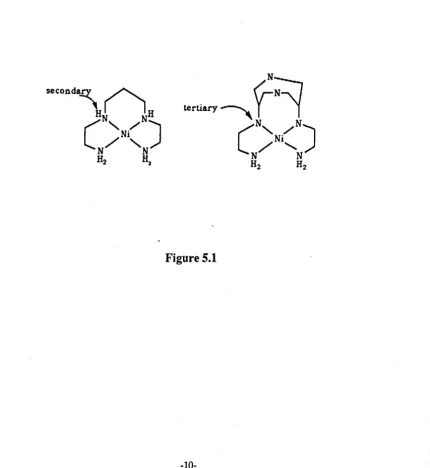
possible explanation is that of donor basicity. The ligand baetbc 2 3 has a high
ligand field strength with Ni(II) even though its Ni-N bond length is similar to that
[image:29.502.58.488.309.777.2]of Ni( en) 2 2
+ ,
the main difference being the introduction of a tertiary nitrogen(Figure 5.1).12
Figure 5.1
-10-Crown ethers
The cyclic polyethers have been found to form a number of 1:1 complexes
with a number of metal ions. 2 4 ,2 5 An interesting property of polyethers is their
ability to selectively bind various cations. Studies have shown that a difference in
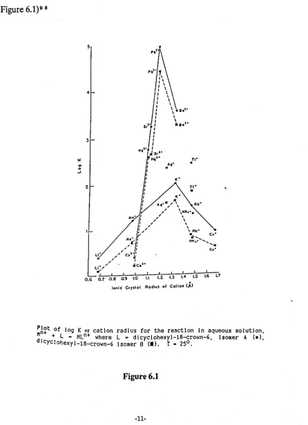
[image:30.499.47.493.161.776.2]stability of 105 , for Pb 2
+
lea
2+ ,
was achieved for dicyclohexyl-18-crown-6.(Figure 6.1) 9 8
)£:
...
0 -' 5 4 ~Pbt •
'I I I I \ I \ I \ I \
f \
I \ I \
8.'-:
\f \
I
T
H,"
!
11°;-' I
, . I
, I u' " " C"~'
, ' _ .t , .
LI', .Co
s,'- 11<1'-\
• ".1'
A,' • n-•- ; I I I I I I I I I IT
O.G 0.7 0,8 09 lO 1.1 I,~ 1.3 l4
.
lS lGIonic Cry.'ol Rodiu:· at Colion (A'
,
~A~t of log K vs cation radius for the reaction In aqueous solution,
+ L - HLn+ where L - dlcyclohexyl-18-crown-6, Isomer A (el,
dl cycl ohexyl-18-crown_6 Isomer B (I). T - 25°.
The size match selectivity has been challenged by Hancock, 2
6 ,2 0 and
he concludes that perhaps it is not just closest fit of cation to "hole" , but the
presence of neutral oxygen donors which determines selectivity. Results have
demonstrated that large metal ions form complexes with an increased stability
when groups containing neutral oxygen atoms are added to existing crowns, where
as small ions tend to show a decrease in complex stability (Scheme 2.1).
0'(~
<-OH
('~)
fI>
[0
0
o
·oJ [0
OJ
[~
~J
<v~~
<VNJ
~NJ
OH'::}
~oJ
OH
PblZn 3.7 ~.6 8
Scheme 2.1
The theory of preorganisation 1 2 is predominant in the work on polyethers.
Crystallographically 18-crown-6 has been shown to adopt a conformation
differ-ent to that in its complexes. This ligand in its free state has a
q
symmetry withthe lone pairs of the oxygens orientated out of the macrocyclic cavity. The
q
conformer has been shown to be 5 kcal mol-1 lower in energy than the compJexed
Da
d conformer21• Interestingly, Kollman2 8 has shown that K
+
prefers theDa
.
d conformer, whilst Na + prefers the C1
structure (Figure7.1).12
-12-Figure 7.1
The structure of Na [18-crown-6], taken from reference 12.
The change for Na
+
is attributed to the conformer C1 allowing shorter Na-O bonds.Mixed donor macrocycles.
Lindoy and co-workers have worked extensively on mixed nitrogen, oxygen
and nitrogen, sulphur macrocycIes. 2 9,30,34,36 The term "goodness of fit" was
coined to explain the selectivity of metals to these macrocycles. The "goodness of
fit"3 1 is defined as the ratio of the bonding cavity radius (RA ) to the Pauling
covalent radius (Rp) of the metal involved. Thus the ratio RAiRp= 1 represents
the perfect match of a metal to the binding cavity. This has been demonstrated
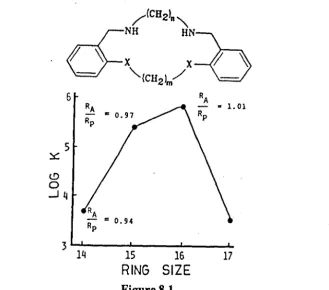
for the nickel (II) complexes of an O 2 N 2 macrocycIe (Figure 8.1), where nand m are varied to produce 14 ... 17 membered rings. 3 2,33 As shown, Figure 8.1, the
[image:32.506.104.457.50.404.2]6
5
~
t!)
o
..Jq
15 16 17
[image:33.513.116.446.33.323.2]RING SIZE
Figure 8.1
A further theory is that of "dislocations". 3" This is where a small change in
a ligand can cause a marked change in geometry, and thus a decrease in complex
stability. For example, the pentadentate (N3 02) macrocycle (Figure 9.1) shows a
change in geometry with Ni (II) by substitution of a methyl for a hydrogen at R.
The selectivity between Cu(II)/Ni(lI) has been greatly increased by the methyl
substitution.3 5
R-H.Me
Figure 9.1
-14-Section
4.1The Macrocyclic Effect
The macrocyclic effect can be related to a Gibbs energy term below.
[ M L ]n +
+
L' --- [
M L']n ++
L~fI9
,
~Sfr
non macro cyclic macrocyclic macrocyclic non macro cyclic
The macrocyclic effect was a term coined by Cabbiness and Margerum 3 1
to account for the greater stability of macrocycles over their open chain
anal-ogues. It was shown that the macrocyclic effect is approximately ten times greater
than the chelate effect for Cu 2
+ ,
with muItidentate amine complexes.Mar-gerum31 attributed the macrocyclic effect to the difference in configurational
solvation of "free" macrocyclic ligands, compared to non cyclic analogues.
How-ever, this has been contested by other workers, such as Kimura 3 8 and Paoletti 3 g.
The driving force of the macro cyclic effect (entropy or enthalpy) has been
a long contested problem. Logically the entropy term should be the dominant
factor, because before co-ordination a macrocyclic ligand should "lose" less
entropy after co-ordination, when compared to an open chain analogue.
Tetra-azamacrocycles
Margerum 4 0 studied the enhanced stability of Ni[14]aneN4 over Ni(
2,3,2,tet), and showed that there was an increase of 14 kcal mol- l in ~fI6, whilst a
decrease of 16 cal deg- l mol- l in ~S9' was observed for the macrocycle. Other work4 l,4 2 supported the theory that the macrocyclic effect was due to solvation
effects. Paoletti,3 9 using a series of aza macrocycles [12]aneN 4 - [15]aneN 4 with
Cu(II) and Zn(II), showed that entropy contributions were more dominant
Cuel!) Complexes Zn(1I) COl1lplexes
Ligand lIUo t.So 1I11° t.So
kcal mol-I cal K -I "'01-1 kcal mol-I cal K-1 moCI
(12/ ane N4 -22.7 +36.2 -14.5
ID/anc N. -29.2 +33.7
114/anc N. -32.4 -14.8
(l5/anc N. -26.S +22.7 -16.S
2.2.2 tel -21.6 +19.5 - 8.9 • +25.0
2.3.2 tct -27.7 +16.5 -11.9 +18.8
3.2.3 tet -25.9 +13.1 -10.6 +15.9
3.3.3 tet -19.5 +12.8 0 - 7.4 +18.0'
Table 3.1
Kimura,·" using .polarographic studies calculated t.S
=
51.4 calK-l mol-1 in good agreement with Paoletti,· 5 showing an entropic driving force
to the macrocyclic effect. However, Paoletti,· 3 studying the relationship
between enthalpy of formation and frequency maxima in electronic absorption
spectra of Cu(II) tetra-amine complexes, concluded that the macro cyclic effect
was not just an enhanced chelate effect. Even though the chelate effect is mainly
an entropy effect, this work showed that the macrocyclic effect was both enthalpy
and entropy driven.
Crown Ethers
The macrocyclic effect is observed in cyclic ethers, and the same
uncertainties in the origins exist. Frensdorff· 6 showed how 18-crown-6 had a
greater stability for Na
+
and K+
over pentaglyme. Kodama and Kimura. 7attributed the macro cyclic effect to a favourable entropy contribution. But
Christensen. 8 showed that for a series of metals (Na
+,
K+,
Ba 2+)
with18-crown-6, in water methanol mixtures, the macrocyclic effect was enthalpic.
The apparent ambiguities in the origins of the macrocyclic effect can only
lead to the conclusion that entropy and enthalpy make varying contributions to
the macrocyclic effect.
-16-Section 5.1.
Synthesis
of
Macrocycles (General)
There have been a number of excellent reviews covering the synthesis of
macrocycles, including nitrogen, oxygen, sulphur and other donor groups such as
phosphorous, and arsenic. 1 1," \I -53
In the synthesis of any donor macrocycle the underlying goal is to produce
a cyclic system in good yield with few or no unwanted side products
(e.g polymers). Most commonly there are three kinds of cyclisation steps used:
1: Richman-Atkins. 5 "
2: Template Synthesis"
3: High Dilution. 7 0
Each method has its own advantages and disadvantages, and these will be
discussed in the following sections.
Crown ethers
The macrocyclic polyethers, especially derivatives of 18-crown-6, have
received notable interest since they have rich chemistry with metal ions. 5 5 The
polyethers have been applied in a number of areas, such as the selective transport
of metals across liquid membranes, chiral recognition, 5 6 and phase transfer
catalysis.5 7
The synthesis of crown ethers is usually carried out under high dilution
conditions (-0.05 M).5 8 However, Pedersen,5 \I in the synthesis of
diben-zo-18-crown-6 achieved high yields (39-48%) with concentrations of - 0.75 M.
This high yield was attributed to a template effect. Greene,6 0 working on the
synthesis of 18-crown-6 postulated that potassium ions acted as a template,
A three dimensional class of crown ethers are the cryptands produced by
Lehn and co-workers,6 1 and synthesised as in Scheme 3.1.
\i:'Kj
~C~0
. t
(b)LiJ
Scheme 3.1
m-n-..,.. .. l
m-n=1.p=2
m-l.n-p-2
m-n-p-2
The overall yield is 25%, which is good given that high dilution methods were
employed. The three dimensional nature of the ligand means that greater
discri-mination for cations is achieved. 6 2
-18-~a~acrocycles
The use of Richman-Atkins5
4 synthesis is probably the most widely used
method in azamacrocycle ligand design. The method involves the condensation
of two moieties in a dipolar aprotic solvent (e.g DMF) (Scheme 4.1).50
DMF
(1)
Sche~e4.1
Recently Kellogg6 3 showed that improved yields could be achieved by
replacing the sodium of the sulphonamide (1) (Scheme 4.1) with cesium,
by addition of CS
2 C03• The CS2 C03 acts as a strong enough base for
deproto-nation, and ring closure. The CS2 C03 method is now widely used in the synthesis
of more elaborate macro cycles, 5 but it is a costly material for simpler
The main advantage of the Richman-Atkins method is that high dilution is not
required; saturated solutions usually give best yields because of increased rates of
cyclisation. Also, the ligand can be fully characterised before metal
complexa-tion. The main drawback of this method is the removal of the protecting groups,
which is carried out under severe hydrolysis conditions (e.g cone H2 SO.).
However, milder detosylation methods have been examined, for example sodium
amalgam in buffered methanol. 6 S
The template method has been used in a number of macrocyc1ic ligand
synthesis. 6 • -61 The first template reaction was carried out by CurtisS (Scheme
1.1), where the nickel held the reacting species in close proximity for reaction.
One of the most widely used template reactions is in the synthesis of [14]aneN. (
cyclam), by Barefield6 8 (Scheme 5.1).
NaCN .
Scheme 5.1
The ligand cyc1am has found a number of uses, and as good precursor for other
macrocyc1es.6 II ,1 1
-20-The final method of high dilution typically involves cyclisation usually
using a diacid chloride and a corresponding amine to produce an amide bond.
The amide linkage can usually be reduced out by BH3.thf or LiAIH •. An
example of this was carried out by Moore 1 0 in the synthesis of a structurally
rigid penta-azamacrocycle (Scheme 6.1).
ElJJ I Toleu.oe
Yield 23~
B~.lhr
Yield 3.3~
Scheme 6.1
The low yield of the final product was attributed to the presence of the rigid
piperazine backbone.
The main disadvantage of the high dilution method is the very dilute
Thia-Macrocycles
These macrocycles are of interest because the larger covalent radius of
sulphur means that M-S bond lengths are increased, and also a "softer" atom is
introduced.
The early synthesis used the reaction of 3-thiapentane-1,5-dithiol and
ethylene bromide to give a mixture ofproducts.(Scheme 7.1)7 2
0J
~s
(1)
Scheme 7.1
(Z)
An improved synthetic route to the tri-thiamacrocycle (1) has been achieved by
Sell mann, using molybdenum as a metal template. (Scheme 8.1).73
, hours. R.T
MoCCO\ CCHsCN\.INMo.)IISC;H.SCzH.S) CHlCN ~
Scheme 8.1
Yield 60'1.
Cooper7 • used the hexathiamacrocycle (2) to stabilise an octahedral low
spin complex of cobalt(II), utilising the fact that the M-S bond lengths are ideal
for low spin coba1t(II).
-22-Other donor Macrocycles ( Arsenic, Phosphorous, Selenium)
The incorporation of other "softer" atoms into the backbone of
macro cycles has been attempted. However, these macrocycles are synthetically
more demanding because of problems with handling procedures and lack of
suitable precursors. Phosphorous, selenium and arsenic are often incorporated
, into macrocyc1es containing other sets (e.g N,O,S). For example, the first
macro-cycle produced by Meek1 5 contained a N 3 P set of donors (Figure 10.1).
Con-versely the first arsenic macrocycle by Kyba 1
8 was based on a tri-dentate ligand
(Figure 10.1).
x-O. NMe. NPb
Figure 10.1
A fully arsenic macrocyc1e was synthesised by Kauffman 1 1 in a moderately good
Z BuLi
2 Ph-AsBll
1
C'HPb
PPh-AsV_h
eel
PPh-As
eel
Pfh
~h
Scheme 9.1
A synthetic route to a fully arsenic macrocyc1e, taken from reference 77.
-24-Recently Tomoda 1 8 has synthesised a macrocycle containing selenium
centres (Figure 11.1). Whether this macro cycle will bind to metals through the
[image:44.515.48.488.143.774.2]selenium atoms is debatable.
Section 6.1
Functionalised MacrocycIes
This is an area which has grown recently, because of the interesting effects
of having extra donor groups attached to a macrocycle. Functionalised
tetra-azamacrocycles 19 have received the most attention, but more recently
triazamacrocycles53 have gained in popularity.
The syntheses of tetra-N-substituted azamacrocyc1es8 0, and tri-substituted
triazamacrocyc1es8 1,82 are the most straightforward.
The preparation of mono functionalised macrocycles requires the use of more
skilful synthesis. Four synthetic pathways are shown in Scheme 10.1.19
Y-OTs
Scheme 10.1
(a) selective alkylation, (b) synthesis of pendant arm in place, (c) selective
pro-tection (d) further functionalisation.
-26-The selective alkylation is the most simple, and involves adding alkylating
agent to excess macrocycle. This method has not been used to a great extent,
because of the difficulty of separation of products from starting materials.
The cyclisation with the side arm already present is a popular method, and
involves cyclisation using either template condensation, high dilution, or
Richman-Atkins. Moore et al.8 3 have used this method in the synthesis of a
tetra-azamacrocycle containing a dimethylamino-ethyl pendant arm (Scheme
11.1 ).
0
rs
N-
~)
Na
(a)
R-N
~R-HN
NHLN.
(b)c~
N-Is
(a)-DMf, 9~'t
Scheme 11.1
When the appropriate side chain has been introduced then further modification
can be carried out. This has been demonstrated by Kaden84 by the
The final approach has the greatest advantage, because once the "free"
nitrogen is produced many different functionalisations can be undertaken. This
has been used to a great advantage by Kaden8
4,8 5 in the synthesis of
mono-functionalised tetra-azamacrocyc1es. Bukowski 8 6 has applied the same
technique to produce a diprotected triazamacrocyc1e (Scheme 12.1).
(a)-PhCOCl
(b) .. NaOEt
(c)- K[OC{CH3 )3 ]
Scheme 12.1
However, no further functionalisation of the "free" amine was attempted, but a
great deal of potential is held by this compound in the synthesis of single pendant
arm triazamacrocyc1es.
-28-Section 7.1
Redox active Macrocycles
There is a current interest in the synthesis of macrocycles containing redox
active centres, especially those containing metallocene 8 7,8 8, quinone 8 9 and
nitrobenzene 9 0 moieties. The interest in such systems is that an interaction
between a redox active centre and a closely bound metal cation may occur. Redox
active centres such as ferrocene are chosen because of the relatively simple
reversible electrochemistry, which can be studied using cyclic voltammetry.
(Section 8.1)
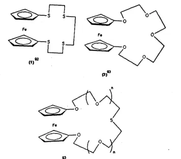
One of the first ferrocene containing macrocyc1es was synthesised by
Vogtle91 in 1979 (Figure 12.1).
[image:48.519.48.473.307.696.2]""',0
Figure 12.1
en
(3)
P.)'D
,..1,0
Saji9
" using macro cycle (2) found that a positive shift in the Elfz occurred on the
addition of alkali metals. This shift occurred because of the decrease in cation
binding of the oxidised form, compared to th~ neutral species. Binding
enhance-ment by electrochemical switching has been observed with other redox active
systems. For example, the lariat crown ether9 0 (Figure 13.1) has been found to
have an increased cation binding when the nitro group is electrochemically
[image:49.521.97.453.39.351.2]reduced.
Figure 13.1
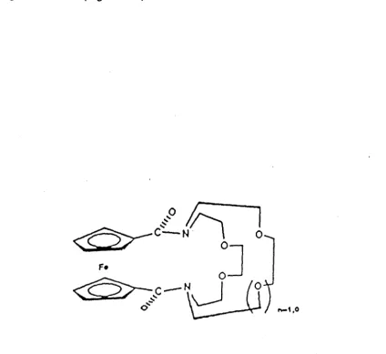
Synthesis offerrocene containing Macrocycles
Synthesis usually involves the reaction of ferrocenoyl chloride, or
1,1' -bis( chlorocarbonyl)ferrocene with a corresponding amine (Scheme
13.1).95,96
Scheme 13.1
Recently the reaction of a phosphorous ylid and a corresponding aldehyde has
been used (Figure 14.1).81
~CH2-PPh,I·
0/"n]
II
;='L\
<i::»
H--<-V ZvOLJO
~
F.
~
Section 8.1.
Cyclic Voltammetry
Cyclic voltammetry is a widely used tool in electroanalytical chemistry,
mainly because it is straightforward to use, and can give a great deal of
information on electrochemical processes. The usual experimental set up
(Diagram 1.1), consists of a working electrode (W.E), counter electrode (C), and
a reference electrode (R.E).
Cotner EItctrode
Diagram 1.1
The working electrode potential is varied between the limits(E1) and (E2)' at a
constant scan rate(v), followed by a reversal (E2 - E1). The corresponding
currents (i) are recorded as a function of the potential (E). Usually a qualitative
study is carried out by varying the limits(E1) and (E2) and the scan rate (v).
Repeat scanning is often carried out, as this gives information on how processes
represented by peaks in the cyclic voltammogram are related.
-32-Reversible Reactions
o
+
n.e~ Ro
=
oxidised form, R = reduced formInitially only "0" is present in solution, and concentrations above a certain
distance from the electrode are maintained by convection. The current measured
depends solely on the mass transport of "0" to the electrode surface. A typical
cyclic voltammogram of a reversible system is shown in Figure 15.1.9 7 The shape
is the result of potential dependant surface changes in the surface concentrations
of the redox systems and simultaneous diffusion processes. The peak current (ip)
can be determined by the Randles-Sevcik equation
:-ip =
-(2.69x10
5).n
3/ 2
.Co.D%.v
%.A.
n = number of electrons, Co = bulk concentration (mol cm-3) D
=
diffusioncoefficient (cm 2 S-l ), A
=
area of electrode (cm 2), v=
sweep rate (V S-l ).To determine whether a system is reversible a number of diagnostic tests can be
[image:52.524.77.472.386.781.2]performed (Table 4.1).91
Table 4.1.
1: 6Ep
=
EpA_EpC=59/nmV2: (Ep-Ep/2)
=
59/n mY.3: ipA/ip C = 1.
4: ipO: v lh.
A more realistic situation is the quasi-reversible system where both charge
transfer and mass transport determine the current observed. Again certain
diagnostic tests can be used to determine such systems ( Table 5.1 ).9 7
Table 5.1
1: ip increases with v 1fz but not proportional.
2: ipA/ip C
=
13: 6.Ep > 59/n mV and increases with increasing v
4: Ep
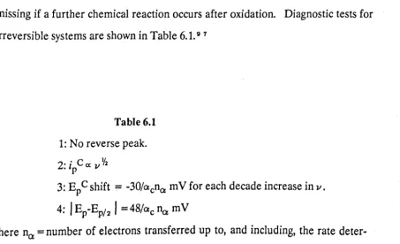
C shifts negatively with increasing v.Irreversible
In such cases the charge transfer at the electrode is slow, and so becomes the rate determining step. Usually the most marked feature of such cyclic
voltammograms is the absence of a reverse peak. However, reverse peaks can be
missing if a further chemical reaction occurs after oxidation. Diagnostic tests for
[image:53.512.44.498.462.738.2]irreversible systems are shown in Table 6.1. 9 7
Table 6.1
1: No reverse peak.
2: ip C ex
.,//2
3: Ep
C shift = -30/acna mV
for each decade increase in v.4:
I
Ep-Ep/21=
48/ac % mVwhere net = number of electrons transferred up to, and including, the rate
deter-mining step. etc = transfer coefficient.
·
I
[image:54.524.58.470.49.384.2]-02
0·1
02
Figure IS.1
The synthesis and study of redox active macrocycles based
on 1,4,8, 11-:-tetraazacyclotetradecane (cyclam)
Section 1.2
Introduction
As described previously (page 29) redox active macrocyc1es have received
considerable attention, especially in the sensing of alkali and alkaline earth metal
ions. 9 9 To date there has been very little interest in the sensing of transition
metal ions, even though these metals are important in a large number of
biologi-cal processes. Beer 1 0 0 recently synthesised two Schiff base crown ether ligands,
with a potential for transition metal ion recognition. In this study; we have
under-taken the synthesis of a series of cyclam based ligands of related importance
(L1 - L5). Some of these ligands combine the properties of azamacrocyc1es in
forming highly stable complexes with transition metal ions, and have a ferrocenyl
redox centre which can be used to sense metal ion complexation.
The main problem area
is:-1: Metal ion selectivity- Most macro cycles will form complexes with a number of
transition metals; for the first row transition metal ions (Mn - Zn), the stability
constants generally follow the Irving-Williams sequence:
(Mn2 + <Fe 2 + <C02 + <Ni2 + <Cu2 + >Zn2 +)
Therefore, to produce a specific transition metal ion sensor is more difficult than
for the alkali metals, where size selectivity is more pronounced for a given
ligand. 2 4,101
Because of its relatively easy synthesis, the ligand
1,4,8,1l-tetraazacyc1otetra-decane (cyclam) was chosen as the base macrocyc1e.1 2 5
In this chapter the syntheses of a series of ferrocene containing azamacrocycles
Section
2.2Results and Discussion
Figure 1.2
Ll Rl = Fc-CO-, R2 =Rs =R" =H
L2 Rl =R2 =R3 =R"
=Fc-CO-Fe
L3.HCI Rl =R2 =Rs = Fc-CO-, R" =H
L3 Rl =R2 =R3 = Fc-CO-, R" =H
The synthesis and electrochemistry of Ll (Figure 1.2)
The general synthesis of this macrocycle is outlined in Scheme 1.2. The
mono-carboxylic acid was synthesised by the procedure of Reeves 1 0 2 in
prefer-ence to other reported procedures, 1 0 3,1 0" because of the good yields (62%),
and experimental ease. A number of reported procedures for the synthesis of the
mono-acid chloride were attempted, 1 0 5,1 0 6 but oxalyl chloride 1 0 1 was found
to give the best yields (77%).
-37-~
(1)o
<O>-~-a
Fe Fe
- - - - l .... ~ Fe
(3)
~
(2)Excess acid ch10rid
Et:JN
Scheme 1.2
(1):AICI3, 2-chlorobenzoyl chloride, CH2 C12, 0° C.
(2): Potassium t-butoxide, H2 O.
(3):Oxalyl chloride.
Excess cyclam
To obtain the ligand Ll an excess of cyc1am was used (- 10 fold), to
ensure that only the mono functionalised macrocyc1e was produced. The excess
cyc1am could be easily removed by dissolving the product in acetonitrile, and
filtering off the insoluble cyc1am. Column chromatography on silica gave the
desired product as a yellow solid on good yield (76%). The structure was verified
by elemental analysis (Table 3.2), F.A.B mass spectrometry (Table 5.2) (Figure
8.2), 1 Hand 1 3 C n.m.r spectroscopy (Tables 1.2, 2.2). The asymmetry of the
cyc1am is shown in both the 1 Hand 13 C n.m.r, by the number of resonances.
Interestingly besides the main resonances in the 1 3 C n.m.r for the cyc1am
back-bone, a series of smaller resonances are observed, indicating a further species is
present. This could be attributed to a hindered rotation (Figure 2.2) around the
N-CO bond, or a "locked in" conformer of the macrocyc1ic ring (Figure 2.1, page
[image:59.499.50.482.405.778.2]7).
Figure 2.2
-39-However, Beer9
6 has shown for a ferrocene bis-crown ether,N-CO bond rotation
is fast on the n.m.r timescale, and only at low temperatures ( - -200 C) does
reso-lution occur. Even at elevated temperatures (-50° C), the 13 C n.m.r of Ll
shows very little change (Figure 3.2); thus hindered rotation is unlikely.
There-fore, conformational "locking in" is the most likely explanation, especially if the
amide nitrogen is Sp2 hybridised. Crystals were obtained to try and solve this
problem, but were found to be unsuitable for X-ray structure determination.
50
ppm
31'1(a)
51'1 41'1 38
ppm
Figure 3.2
Section
3.2
Electrochemistry of Ll
The electrochemistry of Ll is very interesting and depends on the solvent
of study. The cyclic voltammetry in CHa CN (Tetraethylammonium
tetrafluoro-borate TEATFB background) contains only a partial reverse peak even at high
scan rates (Figure 4.2), and no reverse peak at low scan rates. Therefore, the
oxidised form is removed from the electrode surface, as detection is only possible
with fast experimental technique. Titration with Zn 2 + causes the reverse peak
current (ipe) to increase to a point where a reversible system is produced. The
titration curve (Figure 5.2) shows that at an equivalence of 1:1 the current (ipe)
ceases to increase, and so saturation occurs. No shift in the half wave
poten-tial (E1f2) occurs, thus indicating no interaction occurs between the bound metal
and the ferrocene unit. This poor communication between the bound metal and
ferrocene unit is not surprising, as other work has shown that electronic effects
are not transmitted by carboxylato 1 1 1, amino 1 1 2,and dithiacarbamates 1 1 a.
Addition of other transition metal ions (e.g Cu 2 +, NP +) caused similar
increases in the reverse current. However, electrode fouling occurs probably due
to precipitation of the metal complexes, and so was not studied further.
The instability of the oxidised form must be related to the secondary
nitrogen atoms of the macrocyc1ic ring, because once "blocked" (e.g by
complexation) reversibility occurs. Possibly the lone pair of a nitrogen atom
attacks the iron centre of the oxidised form of the
ferrocene:-A=B + ne--- (oxidation of ferrocene centre)
B
+
A---C (C is electrochemically inactive and is not detected)where A
=
reduced form of Ll , B=
oxidised form of L2, C=
breakdown product. When cyclic voltammetry is conducted in H 20 (N aNO a background) a reversiblesystem is observed, as indicated by the linear dependance of peak current on the
square root of the scan rate (Figure 6.2). The breakdown of the oxidised form is
again removed, probably due to solvation of the nitro gens by H2 O. Again the
-41-addition of Zn 2 + has no effect on the E1fz value in the cyclic voltammogram.
IY'
200
300
(a)
(b)
120
A(c)
Figure 4.2
Figure 5.2
A titration curve for the addition of Zn2+ to the ligand Ll. Experimental conditions are given in Figure 4.2
:!
oc-150~1---'
100+
I
••
f
e
e---e-e~
e---50+1---+---+---+---~
0.0 0.5 1.0
EQUIVALENCE OF Zn2
+
l~
(a)
(b)
oo~---~
~
o 30_a. 20
10
O~---r---~---~~---~
0.0 0.1 0.2
V1/ 2 5 -1/ 2
(c)
Figure 6.2
0.3 0 ....
The electrochemistry of Ll (3.98mM) in H20, O.2M NaNO background
Section 4.2
The synthesis and electrochemistry of L2
To obtain the macrocycle L2, the ferrocenoyl chloride was used in a large
excess ( - 10 fold) to ensure tetrasubstitution. Column chromatography on silica
yielded the desired product as a yellow solid in good yield (73%). The structure is
verified by elemental analysis, 1 Hand 1 3 C n.m.r spectrometry (Table 1.2-3.2),
F.A.B mass spectrometry (Figure 8.2, Table 5.2), and X-ray crystallography
(Section 5.2).
The 1 H n.m.r shows no differentiation of the four ferrocene units at 298K,
but on cooling to 253K the three resonances each split into two, indicating a set of
two ferrocenes are becoming inequivalent (Figure 7.2 (a». However, no
resolu-tion of the cyclam protons occurs. A better indicaresolu-tion of the conformaresolu-tion of the
cyclam framework is obtained using 1 3 C n.m.r. At 298K the carbon resonances
of the cyclam are broad, but on cooling to 233K the resonances resolve (Figure
7.2 (b». A fast process must be occurring at room temperature which makes the
ferrocenes equivalent, and broadens the carbon resonances. On cooling a single
conformer is frozen out. To obtain a better picture, a single crystal X-ray
struc-ture was undertaken.
-45-5
T=298K
4 PPM
1
T=253 K
3
Jr---~J---+J----~j~-PPM
Figure 7.2 (a)
Figure 7.2(b)
lH decoupled 13C n.m.r. of L2 in CDCl3 (ref. Me4Si at delta = 0)
CH-N
2
233 K
rcHtl
50,
40
wm
jJ298 K
50
40
30
ppm
[image:67.790.38.755.56.456.2]-47-100 1'J7
1
413l
'I !
70
-136
1
..,.., 154• I
-l 213
I
fr
1071
6~10
j
,A ..
.I1~~.l
Li I, ,,", II
L~ I~I~I
I I~ j .011 l"iI'l "
..
.. ,,~ 1,
. r TS00
(a)
seo
(b)
Figure 8.2
Section 5.2
The crystal structure of L2
The geometry of the macro cycle is shown in Figure 9.2 (a), and is
centro-symmetric; thus a set of two ferrocenes are equivalent. The structure fits in well
with the 1 3 C and 1 H n.m.r data, which indicates a set of two equivalent
ferro-cenes at low temperatures. The nitrogen atoms are Sp2 hybridised with bond
angles attached to C atoms of 120 ± 3°. The Sp2 nature of the nitrogens means
that the macrocycle is unsuitable for chelation. This is better seen in Figure 9.2
(b), which shows that the macrocyclic ring adopts a pseudo chair conformation.
The iron centres are at a distance apart of 8.580A [Fe(1)-Fe(2)] and 9.593A
[Fe(2)-Fe(la)], indicating no interaction should be observed between the
ferro-cene units. L2 shows relatively simple cyclic voltammetry in line with this
conclu-sion. Interestingly the molecule crystalised with four moles of chloroform, which
are shown in the packing diagram. The chloroform molecules sit in the spaces left
by the packing of the individual units (Figure 9 .2( c».
-49-Figure 9.2(a)
The geometry of L2 showing atomic labelling.
Figure 9.2(b)
Structure of the macro cyclic ring, showing the pseudo chair conformation. Ferrocene groups removed for clarity.
[image:71.789.21.750.104.488.2]-51-Figure 9.2(c)
Packing diagram of L2 showing chloroform molecules marked X
[image:72.792.27.688.63.486.2]Table 6.2
Selected bond lengths for L2
Bond lengths (A)
Fe(1)-C(7) 2.090 (29 ) Fe(1)-C(8) Fe(1)-C(9) 2.060 (30) Fe(l)-C(lO) Fe ( 1 ) -C ( 11 ) 2.016 (29) Fe(1)-C(12) Fe(1)-C(13) 2.058 (28) Fe(1)-C(14) Fe(1)-C(15) 2.066 (40) Fe(l)-C(lS) Fe(2)-C(18) 2.044 (26) Fe(2)-C(19) Fe(2)-C(20) 2.084 (28) Fe(2)-C(21) Fe(2)-C(22) 2.030 (25) Fe(2)-C(23) Fe(2)-C(24) 1.985 (30) Fe(2)-C(25) Fe(2)-C(26) 2.015 (32 ) Fe(2)-C(27) Cl(1)-C(201) 1.720 (23 ) Cl(2)-C(201) Cl(3)-C(201) 1.724 (33) Cl(4)-C(101) Cl(5)-C(101) 1.703 (34) Cl(6)-C(101) 0(1)-C(6) 1. 225 (35) O(2)-C(17) N(1)-C(2) 1.458 (30) N(1)-C(3) N(1)-C(6) 1. 346 (35) N(2)-C(4) N(2)-C(5) 1. 431 (35) N(2)-C(171
Selected bond angles for L2
Bond angles (0)
,C (2) -N ( 1 ) -C (3)
C(3)-N(1)-C(6) C(4)-N(2);"C(17) C(2)-C(1)-C(5A) N(1)-C(3)-C(4)
.N (2) -C (5) -C ( 1A)
0(1)-C(6)-C(7) 118.0(16) 116.8(21) 123.4(21) 114.4(19) 114.8(17) 114.9(18) 115.5(23)
-53-C (2) -N ( 1 ) --53-C (6)
C(4)-N(2)-C(5) C(5)-N(2)-C(17) N(1)-C(2)-C(1) N(2)-C(4)-C(3) 0(1)-C(6)-N(1) N(1)-C(6)-C(7) 2.053 2.012 2.051 2.063 2.003 2.043 2.046 2.040 2.045 2.026
1. 716 1.713 1.728 1. 249 1. 455
Section 6.2
Electrochemistry of L2
The tetraamide derivative L2 shows a single reversible cyclic
voItammogram (Figure 10.2), which by coulometric titration is shown to be a four
electron process (Appendix II); this is as expected for four independent
ferroce-noyl units (Section 5.2). Similar behaviour has been observed in
meso-tetrakis( 4-ferrocenylphenyl)porphyrin, where the ferrocenyl groups are also
independent of each other. 1 0 8 The linear dependance of peak current with the
square root of sweep rate again is consistent with a reversible system (Figure
10.2). On addition of Zn 2 + to a solution of the tetraamide there is no change in
the cyclic voltammetry. This can be attributed to the poor donor ability of tertiary
amides, and the Sp2 hybridisation of the nitrogens which makes chelation to a

![Figure 7.1 The structure of Na [18-crown-6], taken from reference 12.](https://thumb-us.123doks.com/thumbv2/123dok_us/9872854.488491/32.506.104.457.50.404/figure-structure-na-crown-taken-reference.webp)