IJEDR2001034 International Journal of Engineering Development and Research (www.ijedr.org) 170
Enhancement of Heat Transfer Performance for
Rectangular Channel with Baffle Heat Exchanger
Using Computational Fluid Dynamics Simulations
1Bhaskar kant gautam, 2Prof. O.P. Shukla 1M.Tech Scholar, 2professor
1Corporate Institute of Science and Technology, Bhopal, India, 2Corporate Institute of Science and Technology, Bhopal, India
_____________________________________________________________________________________________________
Abstract - The main objective of the present work to perform computational fluid dynamics simulations to enhance heat transfer performance for rectangular channel with baffle heat exchanger and find the behavior of carboxymethyl cellulose in the design and hydraulic thermal performance. For that eight different three dimensional CAD model of rectangular channel with baffle spacing 100 mm, 150 mm, 180 mm and 200 mm & height of baffles are 8 mm, 9 mm, 10 mm, 11 mm and 12 mm respectively, is created with the help of design modular of ANSYS workbench. Length of rectangular channel is 600 mm, and the thickness of 1.8 mm. carboxymethyl cellulose as a working fluid is used having flow behavior index n = 0.69, consistency index m = 0.02 Pa and density 997 kg/m3, Specific heat 41000 J/kg-K. The temperature of the liquid inlet is 300 K and the temperature of the rectangular wall of the channel is taken to 267 K, the bottom wall of the rectangular channel and the baffles are calculated as adiabatic and sides of channel considered as periodic zone. For the CFD analysis with second order upwind for the momentum and energy equation is used. Results show that the maximum temperature drop of 28.99 oK due to vortex formation near baffles and maximum heat transfer of 162.601 KW for rectangular channel with baffles observed for baffle spacing 100 mm & height 9 mm. it has also observed that as the spacing reduced the heat transfer increases and the optimum height of baffle is 9 mm observed.
keywords - thermal performance, computational fluid dynamic simulation, baffles, rectangular channel etc.
_____________________________________________________________________________________________________
I. Introduction:
Ribs and insertion of baffles in heat transfer device are efficient to promote fluid mixing of coolants and thus increase cooling performance. Applications of the inclined baffles can be in the large ground based gas turbine blade coolant lane, heat exchangers, chemical engineering process, air-cooled solar collectors and power plants. The use of rectangular channel heat exchanger is very wide because it works beyond the range of force and temperature for oil in the gas, in the liquid and in various applications.
Figure 01: Rectangular channel geometry
There are different types of applications. It is widely used in cryogenic areas, to liquefy air and separate plate heat exchangers. It is widely used in the petrochemical industry and in large-scale refrigeration systems for the production and liquefaction of petroleum products. Fine plate heaters are used in cryogenic applications, ranging from very large rooms to many small rooms. Aluminum brazed sheet strength heat exchangers are widely used in the aerospace industry due to their compact and light weight ratio. These heat exchangers are used only to control the aircraft, cool the aircraft and cool the fuel and fuel oil.
II. Literature Review:
Yuan Ma, Hongbin Yana & Gongnan Xiea [1] They propose a new sandwich panel by introducing the multifunctional pyramidal lattice into a plate fin sandwich panel. The flow and transfer characteristics of this new panel and the parts of the pyramid and hard plates are compared. The results indicate that the lattice of the pyramid sandwich replaced the fluid in the fin sandwich panel. Compared to the empty pyramid lattice sandwich panel, a continuous flow is generated by the formation of flood boundaries on the surface of the clam shell.
IJEDR2001034 International Journal of Engineering Development and Research (www.ijedr.org) 171 A.M. González at el. [3] The proposed numerical model methodology combines wind tunnel experiment data with an aggregate average effect and aggregated total heat aggregated surface efficiency. This technique is applied to heat exchange tubes with woven plates with inline positions.
Sakkarin Chingulpitak at el. [4] This study presents the thermal performance of the sink plate which tends to have different numbers and diameters from the round forging. Based on the same wing plate elements, the available circular forge diameter is limited in number.
J.G. Hernandez-Perez at el. [5] In this work, a new passive cooling system for photovoltaic panels was presented, aiming to reduce its operating temperature and prevent its electrical activity in negative environments. With this goal, a 3D model of heat-stress is developed. The system was evaluated experimentally using CFD software to perform these tasks.
Su Min Hoi at. el.[6] The flow across the plate-fin heat sink under the influence of 2D planar space-filling square fractal grid-induced turbulence at Reynolds number of 2.0×10⁴ is numerically distinguish. The results showed that the severity of large-scale turbulence in turbulence and high speed near the surface of the blades, significant thermal migration from the cooling of the propeller plates.
E. Hosseinirad at el. [7] In the present study, two new settings are proposed for the splitter, ie. PPFHS has winding and waving to improve the total hydropower capacity. Six sophisticated models are investigated and the obtained results are compared to the smooth case. The working fluid is water in the Reynolds range of 50 to 250.
Thamir K. Ibrahim at el.[8] This study aims to assess experimentally and numerically the performance of fins with hollow geometry and without the need for compulsory heat aggregation. The effects of circular concentrations on different number and size of periods, air flow velocity, and various input forces for the thermal and hydraulic performance of these fins, are examined in a continuous area of 24 cm2.
M. Rezaee at el. [9] This study reviews the experimental and numerical hydrothermal properties of heat sinks for cold water pin taps with modified needle length and long wave noise. The new design of the heat pump is called according to different pin lengths, which are low, and high, variable pin length, high and low, variable longitudinal, low and fully drawn and variable longitudinal, high or low pressure.
S. Unger at el. [10] Experimental data was compared with interventions from the literature and informed consent was obtained. In addition, measures of uncertainty were measured. The Nusselt number increases with the fin space in the horizontal tube direction. However, the density of fin and volumetric heat fluxes decreases.
Jian Wen at el. [11] The overall performance of sinusoidal wavy fins in plate-to-final heat exchangers is performed by numerically analyzing the interaction of the structure structure. The results of the voltage distribution analysis indicate that the highest voltage is found in the input and output sections of the finger structure and reach the maximum of the unstable voltage wave-form.
Yuanyuan Zhoua, Jianlin Yub & Ming Gaoa [12] In this article, the heat transfer characteristics of pure refrigerant rain film evaporation were investigated in an attempt to simulate heat transfer with perforated fins. Experiments were conducted under conditions that the air mass ranged from 23 to 49 kg / m2, while the Reynolds number ranged between 200 and 500 with heat. The flow was between 3.2 and 9.5 kW / m2, and the high evaporation was 0.3 MPa.
Maki H. at el. [13] The characteristics of heat transfer and flow of air over a flat winged tube with perforated and nonlinear conductors have completed the calculation. Heat production and pressure measurements were performed using Ansys 15 with RNG k - e standard deviation to estimate the heat transfer coefficient and pressure drop. Free-stream flow starts at 3,4,5,6, and 7 m / s applies to all problems in the experiment and is confirmed with available data.
Muhammad Awais & Arafat A. Bhuiyan [14] This review presents a comprehensive review of various methods of combining heat transfer to reduce pressure and shock in various types of heat exchangers. The aim of this study is to obtain a comprehensive overview of CHX products presented by laboratory and clinical trials to identify target development.
Alem Karima at el. [15] The effects of new cyclic formation on the efficiency of tubular heat fluxes are evaluated numerically. He was worried about a butterfly rash inserted in the freezer of the fridge. They focus on the effect of a baffling image. Three geometric configurations with different PRs were known and five differed significantly from the others.
III.Objective:
There are following objective of the present work
1. The main objective of the present work to perform computational fluid dynamics simulations to predict the effect of Carboxy- Methyl-Cellulose on the design and thermal hydraulic presentation of rectangular channel with baffle heat exchanger.
2. To create new model of rectangular channel with baffle heat exchanger with different baffle pitches and height for batter heat transfer.
3. To perform computational fluid dynamics simulations to predict the effect of Carboxy- Methyl-Cellulose on the new design and thermal hydraulic performance of heat exchangers.
4. To compare the results from both computational fluid dynamic analysis and validate with base paper. IV. Methodology:
IJEDR2001034 International Journal of Engineering Development and Research (www.ijedr.org) 172 computational fluid dynamics simulations to predict the effect of carboxymethyl cellulose on the design and thermal hydraulic performance of rectangular channel with baffle heat exchanger.
Mass flow rate:
𝑚 = 𝜌𝐴𝑉 Where:
ρ: Density of the moving liquid or gas, in kg/m3 V: Velocity of fluid in m/s
A: Flow area, in m2 m: Mass flow rate, kg/Sec Reynolds No.:
𝑅𝑒=𝜌𝑉𝐷 𝜇 Where:
𝑅𝑒= Reynolds Number 𝜇 = kinematic viscosity Nusselt No.:
𝑁𝑢 = ℎ𝐷ℎ
𝑘 = 0.023𝑅𝑒 0.8𝑃𝑟0.4
Where
𝑁𝑢 = Nusselt Number h = Heat transfer coefficient Dh = Hydraulic diameter
K = Thermal conductivity of channel Pr = Prandtl number
Heat transfer coefficient:
ℎ = 𝑘. 𝑁𝑢 𝐷ℎ
𝑊⁄𝑚2. 𝑘
Heat transfer rate:
𝑄 = 𝑚𝑐𝑝(𝑇𝑚𝑎𝑥− 𝑇𝑚𝑖𝑛 ) Where:
Q = Heat transfer rate [W] M = Mass flow rate [kg/Sec] Cp = Specific Heat of fluid [J/kg-K] Tmax = Maximum temperature of fluid [K] Tmin = Minimum temperature of fluid [K]
The computational fluid dynamics analysis is carried out using ANSYS fluent for plate-fin heat exchanger. The input parameters have been taken from the base paper. The governing equations such as continuity equation, momentum equation, energy equations, K equation and ε equations are used to perform this computational analysis.
Conservation of mass or continuity equation: The equation for conservation of mass:
𝜕𝜌
𝜕𝑡+ ∇. (𝜌 𝑣⃗) = 𝑆𝑚 Where 𝑆𝑚= mass added to the continuous phase or any user defined sources. Momentum Conservation Equations
Conservation of momentum equation on an inertial reference frame is described by 𝜕
𝜕𝑡(𝜌𝑣⃗) + ∇. (𝜌𝑣⃗𝑣⃗) = −∇𝑝 + ∇. (𝜏̿) + 𝜌𝑔⃗ + 𝐹⃗ Where p= static pressure
𝜏̿ = stress tensor,
𝜌𝑔⃗ = gravitational body force and 𝐹⃗ = external body forces
Energy Equation:
The energy equation for the mixture takes the following form: 𝜕
𝜕𝑡∑(𝛼𝑘𝜌𝑘𝐸𝑘) 𝑛
𝑘=1
+ ∇. ∑(𝛼𝑘𝑣⃗𝑘(𝜌𝑘𝐸𝑘+ 𝑝)) = ∇. (𝑘𝑒𝑓𝑓∇𝑇) 𝑛
𝑘=1
+ 𝑆𝐸
where 𝑘𝑒𝑓𝑓 = effective conductivity 𝑆𝐸= volumetric heat resources
𝐸𝑘= ℎ𝑘− 𝑝 𝜌𝑘+
IJEDR2001034 International Journal of Engineering Development and Research (www.ijedr.org) 173 V. CAD geometry:
Figure 02: Computational domain of rectangular channel Figure 03: Meshing of rectangular channel
In the present work a three dimensional CAD model of rectangular channel with baffle spacing 180 mm & height 8 mm is created with the help of design modular of ANSYS workbench. Length of rectangular channel 600 mm, Height of rectangular channel 19.8 mm, Channel having baffles situated at a distance 180 mm and the thickness of 1.8 mm. First baffle is placed at a distance of 180 mm from the inlet section. A three dimensional view of the rectangular channel with baffle is shown in figure 02.
Meshing: After completing the CAD geometry of rectangular channel with baffle spacing 180 mm & height 8 mm is imported in ANSYS workbench for further computational fluid dynamics analysis and the next step is meshing in which CAD geometry is separated into large numbers of small pieces called mesh. Types of elements used are hexahedral which is a rectangular in shape with 20 nodes on each element.
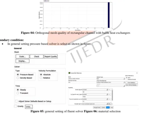
Orthogonal mesh quality: Orthogonal quality is calculated for cells using the vector from the cell centroid to each of its faces and the vector from the cell centroid to centroids of each of the adjacent cells. In the present case the minimum value is 0.99823 and maximum value is 1 and average value is 0.99984, which means the mesh quality is acceptable and very good.
Figure 04: Orthogonal mesh quality of rectangular channel with baffle heat exchangers Boundary condition:
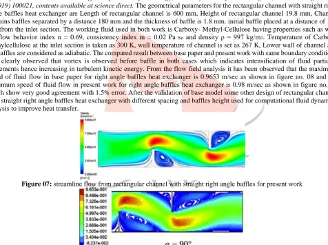
• In general setting pressure based solver is select as shown in figure.
Figure 05: general setting of fluent solver Figure 06: material selection
•
For material selection used Carboxy- Methyl-Cellulose as a working fluid as shown in below figure.With the flow behavior index n = 0.69, consistency index m = 0.02 Pa sn and density ρ = 997 kg/m3, Specific heat 41000 J/kg-K (N. Semmar_2003).
IJEDR2001034 International Journal of Engineering Development and Research (www.ijedr.org) 174 • The temperature at the upper wall of channel is set to 267 K
• To perform heat transfer analysis for rectangular channel with baffle heat exchangers need to on energy equation. • Lower wall of channel and the baffles are considered as adiabatic
•
For the creation of periodic zone following commands have to use. >mesh/modify-zones/make-periodicPeriodic zone [left wall] Shadow zone [right wall] Translational periodic Create periodic zones Auto detect translation vector
•
Select Second Order Upwind for the Momentum and Energy equation.•
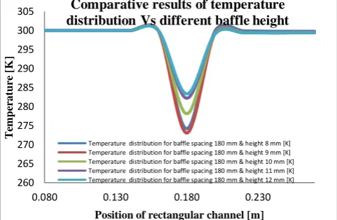
Fluent solver is used to solve this CFD problem. VI. Validation of work:The main objective of the present work is to investigation of optimum design of rectangular channel with straight right angle baffles heat exchanger with different spacing and baffles height using Computational fluid dynamic approach and maximizing thermal performance. For the validation of this work the CAD dimensions of design of rectangular channel with straight right angle baffles heat exchanger is taken from a research paper of Houari Ameur “effect of the baffle inclination on the flow &
thermal fields in channel heat exchanger” department of technology, university centre of Naama, Algeria, Results in Engineering 3 (2019) 100021,contents available at science direct. The geometrical parameters for the rectangular channel with straight right angle baffles heat exchanger are Length of rectangular channel is 600 mm, Height of rectangular channel 19.8 mm, Channel contains baffles separated by a distance 180 mm and the thickness of baffle is 1.8 mm. initial baffle placed at a distance of 180 mm from the inlet section. The working fluid used in both work is Carboxy- Methyl-Cellulose having properties such as with the flow behavior index n = 0.69, consistency index m = 0.02 Pa sn and density ρ = 997 kg/m3. Temperature of Carboxy methylcellulose at the inlet section is taken as 300 K, wall temperature of channel is set as 267 K, Lower wall of channel and the baffles are considered as adiabatic. The compared result between base paper and present work with same boundary conditions it is clearly observed that vortex is observed before baffle in both cases which indicates intensification of fluid particles movements hence increasing in turbulent kinetic energy. From the flow field analysis it has been observed that the maximum speed of fluid flow in base paper for right angle baffles heat exchanger is 0.9653 m/sec as shown in figure no. 08 and the maximum speed of fluid flow in present work for right angle baffles heat exchanger is 0.98 m/sec as shown in figure no. 07 which show very good agreement with 1.5% error. After the validation of base model some other design of rectangular channel with straight right angle baffles heat exchanger with different spacing and baffles height used for computational fluid dynamics analysis to improve heat transfer.
Figure 07: streamline flow from rectangular channel with straight right angle baffles for present work
Figure 08: Streamline flow from rectangular channel with straight right angle baffle from base paper
It has been observed from the base paper that the fluid flows and thermal distribution from rectangular channel with straight right angle baffle heat exchanger attached with baffle show the greater heat transfer in straight baffle. The results of this investigations revealed that the straight baffle give better heat transfer and wider vortex than the other design. However the present work concentrated only on straight baffles with different height and spacing.
IJEDR2001034 International Journal of Engineering Development and Research (www.ijedr.org) 175 Figure 09: Temperature distribution over rectangular channel with different baffle spacing
After performing computational fluid dynamic analysis on rectangular channel with different baffle spacing and height the temperature distribution at rectangular channel have been simulated for 267K (temperature at wall) to 300K (temperature of fluid), due to vortex formation the maximum temperature drop of 16.64 to 25.81 oK is observed near the baffles as shown in figure no. 09.
Figure 10: velocity distribution over rectangular channel with different baffle spacing
After performing computational fluid dynamic analysis on rectangular channel with different baffle spacing and height, the velocity distribution over the rectangular channel with baffle has been observed. The maximum velocity at rectangular channel has been recorded is 1.2 m/sec as shown in figure no. 10
Figure 11: streamline flow from rectangular channel with different baffle spacing
After performing computational fluid dynamic analysis on rectangular channel with different baffle spacing and height, the flow field using stream function ploted on the XY plane for Carboxy Methyl Cellulose as shown in figure no. It has been observed that the baffle creates an obstacle which participates in the separation of the flow and the formation of vortex.
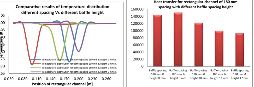
Figure 12: Comparative results of temperature distribution Vs different baffle height
260 265 270 275 280 285 290 295 300 305
0.080 0.130 0.180 0.230
T
em
p
er
at
u
re
[
K
]
Position of rectangular channel [m]
Comparative results of temperature distribution Vs different baffle height
IJEDR2001034 International Journal of Engineering Development and Research (www.ijedr.org) 176 From the above graph it has been observed that the maximum temperature drop of 26.94 oC near the baffle in rectangular channel with baffle spacing 180 mm & height 9 mm as compared with other heights such as 8 mm, 10 mm, 11 mm, & 12 mm. Hence now heat transfer can be checked for some other spacing at 9 mm baffle height. In the present work afart from 180 mm spacing 100 mm, 150 mm and 200 mm pitch is used to chech heat transfer rate.
Figure 13: Comparative results of temperature distribution different spacing Vs different baffle height Figure 14: Heat transfer of rectangular channel for 180 mm spacing with different baffle spacing height
From the above graph it has been observed that the maximum temperature drop of 28.99 oC near the baffle in rectangular channel with baffle spacing 100 mm & height 9 mm as compared with other spacing.
Figure 15: Heat transfer for rectangular channel with different baffle spacing and height
It has been observed from above analysis that as the spacing of baffle is reduced the heat transfer increases with decreasing in temperature.
VIII. Conclusion:
After performing computational fluid dynamics analysis on various designs of rectangular channel with different baffle spacing and height of heat exchanger, It has been concluded that the maximum temperature drop of 28.99 oK and maximum heat transfer of 162.601 KW for rectangular channel with baffles observed for baffle spacing 100 mm & height 9 mm. it has also observed that as the spacing reduced the heat transfer increases and the optimum height of baffle is 9 mm observed.
Reference:
[1] Yuan Ma, Hongbin Yana & Gongnan Xiea “Flow and thermal performance of sandwich panels with plate fins or/and pyramidal lattice” Applied Thermal Engineering 164 (2020) 114468.
[2] Houari Ameur “Effect of the baffle inclination on the flow and thermal fields in channel heat exchangers” Contents lists available at Science Direct, Results in Engineering 3 (2019) 100021.
[3] A.M. González at el. “A hybrid numerical experimental analysis of heat-transfer by forced convection in plate finned heat exchangers” Applied Thermal Engineering 148 (2019) 363–370.
[4] Sakkarin Chingulpitak at el. “Fluid flow and heat transfer characteristics of heat sinks with perforated plate fin” International Journal of Heat and Mass Transfer 138 (2019) 293–303.
[5] J.G. Hernandez-Perez at el. “A new passive PV heatsink design to reduce efficiency losses: a computational and experimental evaluation” Renewable Energy (2019), https://doi.org/10.1016/j.renene.2019.09.088.
[6] Su Min Hoi at.el. “Forced convective heat transfer optimization of platefin heat sink with insert induced turbulence” applied thermal engineering 160 (2019) 114066.
[7] E. Hosseinirad at el. “Effect of splitter shape on thermal-hydraulic characteristic of plate pin-fin heat sink” International Journal of Heat and Mass Transfer 143 (2019) 118586.
[8] Thamir K. Ibrahim at el.”Experimental and numerical investigation for heat transfer augmentation in heat sink using perforation technique” Applied Thermal Engineering 160 (2019) 113974.
265 270 275 280 285 290 295 300 305
0.050 0.080 0.110 0.140 0.170 0.200 0.230 0.260
Te mp e ra tu re [ K ]
Position of rectangular channel [m] Comparative results of temperature distribution
different spacing Vs different baffle height
Temperature distribution for baffle spacing 180 mm & height 9 mm [K] Temperature distribution for baffle spacing 100 mm & height 9 mm [K] Temperature distribution for baffle spacing 150 mm & height 9 mm [K] Temperature distribution for baffle spacing 200 mm & height 9 mm [K]
0 20000 40000 60000 80000 100000 120000 140000 160000 Baffle spacing 180 mm & height 8 mm
Baffle spacing 180 mm & height 9 mm
Bafflespacing 180 mm & height 10 mm
Baffle spacing 180 mm & height 11 mm
Baffle spacing 180 mm & height 12 mm
Heat transfer for rectangular channel of 180 mm spacing with different baffle spacing height
0 50000 100000 150000 200000
Baffle spacing 100 mm & height 9 mm
Baffle spacing 150 mm & height 9 mm
Baffle spacing 180 mm & height 9 mm
Baffle spacing 200 mm & height 9 mm Heat transfer for rectangular channel with
IJEDR2001034 International Journal of Engineering Development and Research (www.ijedr.org) 177 [9] M. Rezaee at el. “Heat transfer intensification in pinfin heat sink by changing pinlength/ longitudinalpitch” chemical
engineering & processing: Process Intensification 141 (2019) 107544.
[10] S. Unger, M. Beyer, J. Thiele & U. Hampel “Experimental study of natural convection heat transfer performance for fin oval tube at different tube tilt angle” experimental thermal and fluid science (2019), doi: https://doi.org/10.1016/j.expthermflusci.2019.03.016.
[11] Jian Wen at el. “Optimization investigation on configuration parameters of sine wavy fin in platefin heat exchanger based on fluidstructure interaction analysis” international journal of heat and mass Transfer 131 (2019) page from 385–402. [12] Yuanyuan Zhoua, Jianlin Yub & Ming Gaoa “An experimental study of falling film evaporation in vertical channels with
perforated fins of a plate-fin heat exchanger” Chemical Engineering & Processing: Process Intensification 145 (2019) 107672.
[13] Maki H. Zaidan, Aadel A.R. Alkumait &Thamir K. Ibrahim “Assessment of heat transfer and fluid flow characteristics within finned flat tube case studies in thermal engineering 12 (2018) 557–562.
[14] Muhammad Awais & Arafat A. Bhuiyan “Heat and mass transfer for compact heat exchanger design:- an review” International Journal of Heat and Mass Transfer 127 (2018) 359–380.