Centre
of
Excellence
for
Nuclear
Materials
Workshop
Materials
Innovation
for
Nuclear Optimized
Systems
December 5-7, 2012, CEA – INSTN Saclay, France
Philippe PAREIGE et al.
CNRS, University of Rouen (France)
Nuclear Materials Characterization by Tomographic
Atom Probe
Workshop
organized
by:
Workshop
Materials
Innovation
for
Nuclear
Optimized
Systems
December 5-7, 2012, CEA – INSTN Saclay, France
Nuclear Materials Characterization by Tomographic Atom Probe
Philippe PAREIGE
1, Bertrand RADIGUET
1, Cristelle PAREIGE
1 1CNRS, Groupe de Physique des Matériaux, UMR CNRS 6634, Université et INSA de Rouen Faculté des Sciences Université de Rouen (Saint Etienne du Rouvray, France)
Nuclear Materials (reactor vessel, internal structures, fuel rod, glass containment…) undergo degradations under neutron irradiation due to particle/matter interaction. These degradations modify their physical, chemical and mechanical properties and are likely to impact the safety or the operation length of the concerned structures. It is thus crucial to anticipate and quantify these effects in order to ensure an efficient use of present or future nuclear reactors. The phenomena controlling materials behavior under irradiation are on an atomic scale.
Understanding the phenomena on this scale is thus essential for the development of a predictive simulation and understanding of the ageing and safety of materials. This atomic scale is the first floor of the multiscaleapproach necessary formodeling andprediction,as illustrated in figure 1.Themajor technique inthisfield istheTomographic Atom Probe, nanoanalytical technique withatomicresolution. Atom Probe Tomography (APT) is an extension in 3D of the atom-probe field ion microscope (APFIM), an instrument designed in the late sixties by E.W. Müller [1]. APT is the only approach able to map out the 3D distribution of chemical species in a material at the atomic-scale. The principle of APT [2,3] is based on the field evaporation of surface atoms of the specimen (a sharply pointed needle, R ~ 50 nm) and the chemical identification of field evaporated ions by time-of-flight mass spectrometry. The position of atoms at the sample surface is derived from the impact position of ions striking the detector. A major advantage of APT is its quantitativity. The local composition in a small selected region of the analyzed volume is simply derived from the number of atoms of each observed species. This is a big advantage compared to number of other instruments. No calibration is required. The in-depth resolution, independent of technologic details of these instruments, reaches 10 picometers. Atomic planes can therefore be imaged and the chemical order can be both exhibited and characterised. The lateral resolution is close to 0.5 nm. This makes it possible the quantitative analysis of small precipitates in alloys or the study of solute segregation to crystal defects (as illustrated in figure 2 [4]).
The last few years have been the witness of a major breakthrough in the development of APT. Formerly limited to metals or good conductors, the implementation of ultra-fast pul-sed laser to the instrument opened APT to semi-conductors or oxides [5, 6]. Laser pulses give rise to very rapid thermal pulses that promote the field evaporation of surface atoms.
Space
1 nm 1m
Time
1 s
1 ps 40 nm
Atoms Electrons Microstructure 10 mm Dislocations and irradiation defects Structure 1mm 1 y 1m 1 c 1 mm 10 m
Electronic Structure Molecular DynamicsObject or Event Monte Carlo
Crystal Plasticity (CP) Homogenization
Finite Elements (EF)
Monte Carlo Clusters Dynamics
Formation and mobility of point defects (dp)
Evolution of Dislocations Network defects clusters, solute
Multi-scale Modeling
Dislocations Dynamics (DD) TEM TAP SANS Mechanical Tests SEM EBSD Déformation Behavior rules Ab initio
Fig. 1: Development of numerical tools and experiments for a multiscale approach.
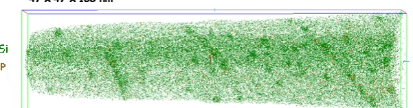
Fig. 2: Tomographic Atom Probe experiment in a RPV steel. Each dot represents an atom (Si or P here). Irradiation indu-ced clusters and segregation on dislocation lines are visible.
EPJ Web of Conferences 51, 03004 (2013) DOI: 10.1051/epjconf/20135103004
© Owned by the authors, published by EDP Sciences, 2013
Workshop
Materials
Innovation
for
Nuclear
Optimized
Systems
December 5-7, 2012, CEA – INSTN Saclay, France
In addition, a wider field of view is achieved so that larger area of analysis are obtained (~100x100 nm2) improving therefore statistics together with shortening the number of analyses required to get the relevant information. This technique brings key information for the understanding of the evolution of the microstructure of nuclear reactor steels under neutron irradiation, evolution responsible for their hardening and embrittlement. The basic principles of the technique, the sample preparation and some examples of applications in the field of “Metals under Irradiation” [7,8,9] will be presented and discussed.
References
[1] E.W. Müller, J. Panitz, And S.B. Mc Lane. Rev. Scie. Instrm.: 39, 83 (1968).
[2] A. Cerezo, I. J. Godfrey And G. D. W Smith. Rev. Sci. Instrum: 59, 862-866 (1988).
[3] D. Blavette, A. Bostel, J.M. Sarrau, B. Deconihout And A. Menand: Nature, 363, 432-435 (1993). [4] Huang Hefei, Influence de l’irradiation aux neutrons sur le vieillissement des aciers de cuves des
réacteurs nucléaires à eau pressurisée. PhD 2012, Rouen University.
[5] B. Deconihout, F. Vurpillot, B. Gault, G. Da Costa, M. Bouet, A. Bostel, D. Blavette, A. Hideur, G. Martel: M. Brunel. Surf. Interface Anal. 39, 278, (2007).
[6] B. Gault, F. Vurpillot, A. Vella, M. Gilbert, A. Menand, D. Blavette. B Rev. Sci. Instr. 77, 043705 (2006).
[7] A. Etienne, B. Radiguet, N.J. Cunningham, G.R. Odette, R. Valiev, P.Pareige, Comparison of radiation induced segregation in ultrafine-grained and conventionnal 316 austenitic stainless steels. Ultramicroscopy 111 (2011) 659-663.
[8] M. Brocq, B. Radiguet, S. Poissonnet, F. Cuvilly, P. Pareige, F. Legendre, Nanoscale characterization and formation mechanism of nanoclusters in an ODS steel elaborated by reactive-inspired ball-milling and annealing. Journal of Nuclear Materials 409 (2011) 80-85 (doi:10.1016/j.jnucmat.2010.08.043).
05-07 /12/ 2012
CEA Saclay
Nuclear materials characterization by
Tomographic Atom Probe
P. Pareige, B. Radiguet, A. Etienne and C. Pareige
Groupe de Physique des Matériaux
UMR CNRS 6634
Space
1 nm
1
µµµµ
m
Time
1 s
1 ps
40 nm
Atoms
Electrons
Microstructure
10 mm
Dislocations and
irradiation defects
Structure
1mm
1 y
1m
1 c
1 mm
10 m
Electronic Structure
Molecular Dynamics
Object or Event Monte Carlo
Crystal Plasticity (CP)
Homogenization
Finite Elements (EF)
Monte Carlo
Clusters Dynamics
Formation and mobility
of point defects (dp)
Evolution of Dislocations Network
defects clusters, solute
Multi-scale Modeling
Dislocations Dynamics (DD)
TEM
TAP
SANS
Mechanical
Tests
SEM
EBSD
Déformation
Behavior rules
Ab initio
10 nm
Challenge in Materials Science
Need to explore each scale and to link them
Need to explore more and more at small scale
To understand
Physical properties
Reliability
Ageing
Contents
Basic Principles
Field evaporation
Time of flight mass spectrometry
3D reconstruction
Sample preparation
Electropolishing
Focused Ion Beam
Application to nuclear materials
RPV steels
Internal structures
FeCr alloys
Prof. E. W. Müller
FIM (1955)
FLEXTAP
LEAP
[110]Feα d(110)= 0.2 nm
Distance (x)
Ion n
+atom
Basic Principle: Field Evaporation
Sample
Field Ionisation and Field Evaporation
3D Reconstruction
Basic Principle: How to obtain High Elec. Field
R
R ~ 100nm
V ~ 1000V
Thin needle shaped samples
E ~ 10V.nm
-1
R = 20-50 nm
V = 1 - 15 kV
ββββ
= 3 - 8
Field Ion Microscope
=
Field Ionisation of gas atoms at the surface of a metallic needle
20 K
à
80 K
Gas Atoms
Ionised Gas Atoms
Detector
Electrical field
Basic Principle: ToF mass spectrometry
Principle scheme of an AP
(100 ns)
Start signal
Stop signal
Energy conservation
Potential energy
Kinetic energy
Mass over charge ratio
Basic Principle: TOF and 3D reconstruction
3D Atom Probe, a projection microscope
Ion Impact
Atom position
Basic Principle: Mass spectrum
Mass spectrum
54
Fe
2+57
Mn
2+56
Fe
2+57
Fe
2+58