135
Vision-Based Object Tracking Algorithm With AR.
Drone
It Nun Thiang, Dr.LuMaw, Hla Myo Tun
Abstract: This paper presents a simple and effective vision-based algorithm for autonomous object tracking of a low-cost AR.Drone quadrotor for moving ground and flying targets. The Open-CV is used for computer vision to estimate the position of the object considering the environmental lighting effect. This is also an off-board control as the visual tracking and control process are performed in the laptop with the help of Wi-Fi link. The information obtained from vision algorithm is used to control roll angle and pitch angle of the drone in the case using bottom camera, and to control yaw angle and altitude of the drone when the front camera is used as vision sensor. The experimental results from real tests are presented.
————————————————————
1. Introduction
In recent years, unmanned aerial vehicles (UAVs) have become a very active field of research and made a huge progress in automated navigation, surveillance, military application, rescue tasks and agriculture. Among various research areas on UAV, vision based autonomous control has become the main interest for the environment where GPS is denied. A noble vision-based tracking moving target using a quadrotor is investigated with two controllers: PID controller is designed for stability and for tracking moving target LQG is implemented based vision algorithm [1]. Landing on the predefined mark and position control is introduced with vision based 3D position estimation and a cascaded control structure by using optical flow sensor for velocity [2]. In 2010 an affordable AR.Drone quadcopter, the necessary sensors, especially built-in two cameras, are already equipped and with suitable software interface has appeared in the commercial UAVs. The AR.Drone can be used for vision based robotic research fields by doing experiments required to design a control structure on visual navigation and localization using on-board cameras in control feedback [3]. Autonomous landing and searching land-mark which is defined by using two coloured-cycles is presented with an effective PID control [4]. In this work, the AR.Drone is used as a vision sensor for tracking color-object with both cameras (front and bottom). With the help of Open-CV, a computer vision algorithm is well designed and the experimental results are also presented.
2. About AR. Drone
AR. Drone is a low-cost quardrotor introduced by a French company in 2010, as a high-tech toy for augmented reality (AR) game that can be controlled by any wifi available device (such as iPhone, iPad, laptop, etc.). It consists of a carbon-fiber structure, polystyrene body, four electrical brushless motors, removable battery, sensors, control electronics, and two hulls (indoor and outdoor) preventing of damage.
A. Hardware and Software
The sensory in Drone comprises of 3-DOF accelerometer, 3-DOF gyroscope, sonar based altimeter, and two cameras- one forward and one bottom. The control board is based on ARM9 processor running at 468MHz with 128 MB of DDR RAM running at 200MHz. The drone can speed up to 5ms-1 and its battery provides enough energy up to 13 minutes of continuous flight with maximum payload of 100g. The AR.Drone 2.0, used in this work, has 360p (640x360) or 720p (1280x720) image resolutions for both cameras.
(a)
(b)
Figure 1: AR.Drone (a) with outdoor hull (b) with indoor hull The control board of the AR.Drone, running based GNU/Linux distribution, takes care of the stabilization, and provides basic maneuver. It also supports to communicate with the user interface device including an ad-hoc Wi-Fi.
B. AR.Drone 2.0 SDK
The official side supports an open-source API for the developer to design own application for the drone. The API library is written in C and runs on iOS, Andriod and Linux platform. A wifi communication service is needed for the application, and the drone and device installed API will be server and client respectively. It allows four communication services (command, navigation, video stream, and control) for the user to control and configure the drone using API.
C. AT commands
AT*PCMD_MAG=21625, 1, 0, 0, 0, 0, 0, 0<CR>AT*REF=21626, 290717696<CR>
D. Navigation data and video stream
The navigation data (the information of the drone) can be requested from the client API by sending AT command. The drone will send the navigation data package via UDP Nav-channel periodically (<5 ms), which includes tilt angles, velocities, altitude, and etc. The video stream is sent from the drone to the client device on TCP port according to the user’ selected camera. Its frame rate can be adjusted between 15 and 30 FPS.
3. Imaging Processing method
Object detection and segmentation is the most important and challenging fundamental task of computer vision. It is a critical part in many applications such as image search, scene understanding, etc. However it is still an open problem due to the variety and complexity of object classes and backgrounds. The easiest way to detect and segment an object from an image is the color based methods. The object and the background should have a significant color difference in order to successfully segment objects using color based methods.
A. Filtering
The filtering is an important in image processing to smooth the image. Among different methods, the Gaussian filter is the most useful filter that is done by convolving each point in the input array with a Gaussian kernel and then summing them all to produce the output. A 2D Gaussian kernel is applied in this vision algorithm.
B. Thresholding
Thresholding is the simplest method of image segmentation. The basic algorithm behind thresholding is to select those pixel values whose value is greater than the threshold (fixed by us) and reject the rest of them.
P(x,y) = 1 if P(x,y)>Threshold = 0 otherwise
Since all the selected regions are indicated by 1 and rest by 0 what we get is a binary image. OpenCV provides two functions cvThreshold and cvInRangeS for the purpose of thresholding.
C. RGB to HSV image
The RGB color format can represent any standard color or brightness using a combination of Red, Green and Blue components. For efficiency, this is typically stored as a 24-bit number using 8-24-bits for each color component (0 to 255). Unfortunately when it comes to computer vision, RGB values will vary a lot depending on strong or dim lighting conditions and shadows, etc. In comparison, HSV is much better at handling lighting differences, and it gives an easy to use color value. So, the RGB image received from the drone is converted to HSV image in this application. HSV color space is also consists of 3 matrices, HUE, SATURATION and VALUE. In OpenCV, value range for HUE, SATURATION and VALUE are respectively 179, 0-255 and0-0-255. HUE represents the color, SATURATION represents the amount to which that respective color is mixed with white and VALUE represents the amount to
which that respective color is mixed with black. The HUE is unique for that specific color distribution of that object. But SATURATION and VALUE may be varying according to the lighting condition of that environment. Hue values of basic colors
Yellow 22- 38
Green 38-75
Blue 75-130
Violet 130-160
Red 160-179
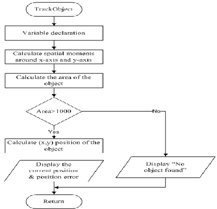
D. Calculate the Position of the Center of the Object
In this application, we use the position of the center of the blue-color object in the image to know the position of AR.Drone. After threshold process for selected color as explained above, we have to calculate 1st order spatial moments around x-axis and y-axis and the 0th order central moments of the binary image.0th order central moments of the binary image are equal to the white area of the image in pixels. The center of selected color object can be specified in pixels as follow:
xobj = / (1)
yobj= / (2)
Where , and are 1st order spatial moment around x-axis, 1st order spatial moment around y-axis and 0th order central moment respectively. If the white area of the binary image is less than or equal to 1000 pixels, there are no objects in the image because the object is expected to have an area more than 1000 pixels. For two dimensional order movements [5] of the image represented in a discrete function can be calculated as
∑ ∑ (3)
Where and correspond to the x-y coordinates of the image. For object tracking, the required pitch and roll can be directly calculated from object image coordinates. The distance between the center of the colour object and the real position of the drone can be calculated as:
ydist( pitch error)= (image height/2) - yobj
xdist (roll error) = (image height/2) - xobj
The roll and pitch of the drone are defined on the x and y coordinates in the image.
4. Implementation
The application software is implemented using visual studio and open-cv library based on the CV Drone (puku0x). It includes four main parts manual control, getting nav-data and video stream, and sending commands to the drone. The main loop operates with 30 Hz because the command should be sent on a regular basis (30 times recommended) for the stability.
A. Connecting the Drone with client API
137 controlled by any device that can support a Wi-Fi
connection. The connection process is as follows:
When the drone is powered up it creates a Wi-Fi network with the default ESSID of the format ardrone_xxx where xxx is typically 192.168.1.1.
As the drone is acting as the server, the client device requests an IP address from the drones DHCP server.
The drone's DHCP server then allocates the client program an IP address. This IP address is the drone's IP address plus a random number between 1 and 4 for AR.Drone 2.0 (used in this research) .
After that, the communication can be done between the client and the drone via service port (UDP and TCP).
B. Object Detection and Tracking
The received RGB image is converted to the Hue Saturation Value (HSV) color space after filtering process using the cvCvt-color OpenCv method. This allows a specific HSV value to be set so that custom object colors can be tracked. To allow the user to set their own HSV values a window is created where the each of the HSV values can be customized to a blue color. Once the HSV values are set, a binary image is created from the original image so that a black and white image can be obtained from the object being tracked.
Figure 2: Overview Flowchart for Object Detection and Tracking
The position of the drone with respect to the color object in the image is calculated when the object is found. The set point is defined as the center of the image (640x360). In this case, the user can choose the camera, bottom or front.
5. Experimental Results
This section presents the experiments conducted on the AR.Drone. The drone sends the image from both cameras (user selected) to the laptop.The design software in laptop processes on the image using open-cv for filtering, converting HSV image, thresholding, calculating the position error. Based on those errors, it sends the control signal (roll, pitch, and altitude) to the drone to track the objects. The software runs at a rate of 30 Hz.
A. Finding the HSV threshold values and Position Error
After basic image processing steps, we need to find the HSV threshold value of the object under experimental environment in order to reduce the lighting effect. Being different resolutions in cameras, the performance of the front one is better than of the bottom camera as shown in figures.
HSV Track bar Original image
Figure 3: HSV image Position and Position Error
Figure 4: Result using Front Camera
In these experiments, the blue-color object is placed about 1m and 2m for the front and bottom cameras respectively. The position errors in x-axis and y-axis are calculated in pixels by subtracting the center of the object and the image (640x360 resolutions).
B. Tracking ground target
Figure 5: Tracking Ground Object with Bottom Camera In this experiment, the Drone is tracking the ground object about 2m from the ground. According to this experiment result, in order to be able to track the moving target, the drone’s maximum velocity has to be larger than that of the moving target. In this case, the maximum velocity of the drone is 1(m/s).
C. Tracking flying target
Figure 6: Tracking Flying Object with Front Camera Figure 6 shows the real test result for tracking flying object with front camera, based on color-based object detection with the same color as in figure 5. In this case, for tracking flying object, vertical speed and yaw rate angle are important to track robustly flying target object. According to SDK developer guide, the drone’s maximum vertical speed and yaw rate angle are 1(m/s) and 100(degree/s).
6. Conclusion
139
References
[1] Denys Bohdanov, “Quadrotor UAV Control for Vision-based Target Tracking Task,” in Graduate Department of Aerospace Engineering, University of Toronto, 2012.
[2] Seven Lange, Niko Sunderhauf, Peter Protzel, “A Vision-Based Onboard Approach for Landing and Position Control of an Autonomous Multirotor UAV in GPS-Denied Environments,” in IEEE Xplore, 2010.
[3] Martin Saska and Tomas Krajnık and Jan Faigl and Vojtech Vonasek and Libor Preucil,“Low cost MAV Platform AR.Drone in experimental verifications of methods for vision-based autonomous navigation,” in IEEE/RSJ International Conference on Intelligent Robots and systems, October 7-12,2012,Vilamoura, Algarve, Portugal.
[4] Roman Bartak, Andrej Hrasko, David Obdrzalek, “On Autonomous Landing of AR.Drone Hands-on Experience,”Proceeding of the Twenty-Seventh International Florida Artificial Intelligence Research Society Conference, 2014.
[5] M.-K Hu: “Visual Pattern Recognition by Moment Invariants”, IRE Transactions on Information Theory (1962) 179-187.
[6] Pierre-Jean Bristeau, François Callou, David Vissière, Nicolas Petit, “The Navigation and Control Technology inside the AR.Drone micro UAV,” in the 18th
IFAC World Congress, Milano (Italy), August 28-September 2,2011.