352 |
P a g e
CORNER TRUNCATED MICROSTRIP PATCH
ANTENNA
Nazia Hasan
1, Dr.S.C.Gupta
21
Student ECE Deptt. UTU Dehradun,Uttarakhand Technical University, Dehradun(India)
2
ECE Deptt. DIT Dehradun,Dehradun Institute of Technology Dehradun(India)
ABSTRACT
A square Microstrip patch antenna at frequency of 3.4 GHz is designed in this paper. This structure will give
linear polarization. We have truncated the opposite corners from square patch antenna to achieve circular
polarization. Microstrip feed line is used in this design. Ansoft HFSS is used to design this structure.
Keywords:
Microstrip Patch Antenna, Microstrip Feed Line, Ansoft HFSSI.INTRODUCTION
Micro-strip patch antennas have always been an attractive choice for the researchers, especially in the field where cheap, low profile, light weighted and easy to fabricate structures are desired such as in Wireless or Mobile communication. Microstrip patch antennas used because of its various advantages like compatibility with integrated circuits, conformal configuration, light weight, easy to fabricate and so on. Microstrip patch antennas usually designed with linear polarization but in some applications such as satellite communication circular polarization is desired because circularly polarized antennas are very insensitive to transmitter and receiver orientation. A micro-strip patch is one of the most widely used radiators for circular polarization generation. A microstrip patch antenna which is linearly polarized may be easily converted in to circularly polarized patch antenna after some modifications in the shape of structure and after cutting slots in the structure.
In the work presented in this paper a microstrip patch antenna is designed at the frequency of 3.4 GHz and this structure will produce linear polarization. The opposite corners of the structure are truncated as a result of which the linear polarization of the antenna is converted in to circular polarization. In this way circular polarization is achieved.
Polarization diversity of reception is also very important to counter the effects of fading in communication, especially in mobile communication.
Table 1 shows the design parameters of simple micro-strip patch antenna without truncated opposite corners.
II
.THE
ANTENNA
STRUCTURE
353 |
P a g e
S.no. Parameter Value
1. Frequency 3.4 GHz
2. Dielectric constant of substrate Duroid (tm) 2.2
2. Width of patch 23.82 mm
3. Length of patch 23.82 mm
4. Width of quarter wave transformer 1.144 mm
5. Length of QWT 20.8325 mm
6. Width of 50 ohm transmission line 4.84 mm
7. Length of 50 Ω TL 20 mm
8. Polarization Linear
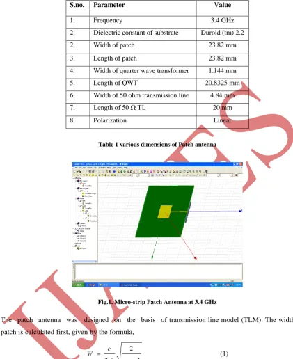
Table 1 various dimensions of Patch antenna
Fig.1. Micro-strip Patch Antenna at 3.4 GHz
The patch antenna was designed on the basis of transmission line model (TLM). The width of the patch is calculated first, given by the formula,
1 2 2 r f c W
(1)
where εr the dielectric constant of substrate, W is is the width of the patch and H is the height of the substrate. The patch we have used in this model is square patch, so the length and the width both are the same. The dimensions of the patch are extended to account the fringing effect; the extension is given by,
) 8 . 0 / ).( 258 . 0 ( ) 264 . 0 / ).( 3 . 0 ( 412 . 0 h W h W h L eff eff (2)
354 |
P a g e
eff eff f c L 2 (3)
Patch resonant length L is given by,
L = Leff – 2Δ (4)
Using the values given by TLM approximation, parameters for the antenna were calculated for 3.4 GHz. The dielectric substrate Duroid (εr = 2.2) with height h = 1.57 mm is used.
Quarter wave transformer is a very useful and practical circuit for impedance matching and it also provides a simple transmission line circuit that further illustrates the properties of standing waves on a mismatched line.
When it is desired to match a load resistance RL with a feed line of characteristic impedance Z0, a piece of lossless transmission line of characteristic impedance Z1 and λ/4 length is used to connect them, so to make the reflection coefficient Γ=0 looking into the λ/4 matching section. The matching impedance Z1 is given by the expression.
L
R Z
Z1 0 (5)
Quarter wave transformer
The length of the transformer is λ/4, which gives length 20.8325. The width of the conductor is given by the formula 2 ) 2 exp( ) exp( 8 A A h w (6)
for Z0 (εr) 1/2
>89.91, that is A > 1.52 and for Z0 (εr) 1/2
<= 89.91, that is A <= 1.52
r r r B B B h w 61 . 0 39 . 0 ) 1 ln( 2 1 ) 1 2 ln( 1
2 (7)
Where, r r r r Z A
0.11
23 . 0 1 1 2 1 60 2 / 1 0 (8)
355 |
P a g e
The dimensions of the ground plane were taken according to the lengths of the patch, the quarter wave transformer and the 50-Ohm transmission line. So the length of the ground plane, we calculated is given by;Lg = L + LQWT + LTL (9)
Where L is the length of the patch, LQWT is the length of the quarter wave transformer; LTL is the length of the 50-Ohm transmission line.
The Patch antenna and the ground plane are made of copper sheet; the thickness of copper sheet is taken to be 0.1 mm. The antenna is fed RF signals ranging from 2 to 5 GHz, at the port with the help of a waveport as shown in fig.1.The antenna without truncated opposite corners has linear polarization. S-parameter plot of without truncated corners patch antenna is shown in figure given below
Fig.2 S-parameter plot of simple patch antenna
Next step is to change the polarization of this antenna from linear to circular. For this purpose, opposite corners of the patch are truncated. The dimensions of the truncated corners being calculated according to the following equation
Length a = length of patch / 5 (10)
The design of opposite corner truncated micro-strip patch antenna is shown in figure 3.
356 |
P a g e
Fig.4 Axial ratio plot of opposite corners truncated
This truncated opposite corners changes the polarization of the antenna from linear to circular this circular polarization can be verified by plotting the axial ratio as shown in figure3. For circular polarization the axial ratio should be 1. The axial ratio of corner truncated patch antenna is 1.01. The axial ratio plot of opposite corner truncated antenna is shown in figure 4.
Fig 5. S11 plot of opposite corners truncated antenna
As desired the polarization of this antenna has now changed to circular because of the truncated corners but the resonant frequency is changed because of truncating the corners of the patch, s-parameter plot showing the resonant frequency of corner truncated microstrip patch antenna.
III. RESULTS & ANALYSIS
Software and settings
357 |
P a g e
Analysis of resultsThe simulation results are shown in figures below; from figure 2. it can be observed that the reflection coefficient S11 for linearly polarized antenna without any truncation showing resonance at frequency 3.3 GHz. Figure 4 shows the axial ratio for opposite corners truncated antenna, as desired its magnitude is 1.01, which shows that this antenna posses circular polarization.
Figure 5 shows s-parameter plot of corner truncated patch antenna its resonant frequency has changed after truncating the corners that is 3.15 GHz.
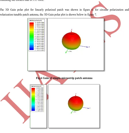
The 3D Gain polar plot for linearly polarized patch was shown in figure 6, for circular polarization and polarization tunable patch antenna, the 3D Gain polar plot is shown below in figure 7.
Fig.6 Gain of simple microstrip patch antenna
Fig.7 Gain of corner truncated patch antenna
358 |
P a g e
IV.
CONCLUSION
AND
FUTURESCOPE
The proposed antenna is suitable for use in communication, defense applications, surveillance and countermeasures.
ACKNOWLEDGEMENT
The authors are thankful to DEAL (Defense Electronics Applications Laboratory), Dehradun for extending their laboratory to use Ansoft HFSS.
REFERENCES
[1] Symeon Nikolaou, Ramanan Bairavasubramanian, Cesar Lugo, Ileana arrasquillo, Dane C. Thompson, George E. Ponchak, Manos M. Tentzeris, “Pattern and Frequency reconfigurable Annular Slot Antenna Using PIN Diodes” IEEE transactions on antennas and propagation, vol. 54, No.2, February 2006.
[2] S. Silver, Microwave Antenna Theory and Design. New York: McGraw-Hill, 1949.
[3] Y. J. Sung “Reconfigurable Patch Antenna for Polarization Diversity” IEEE Transactions On Antennas And Propagation, vol. 56, NO. 9, September 2008.
[4] Boyon Kim, Student Member, IEEE, Bo Pan Student Member, IEEE, Symeon Nikolaou,Young-Sik Kim, Member, IEEE, John Papapolymerou, Senior Member, IEEE, and Manos M. Tentzeris, Senior Member, IEEE”A Novel Single-Feed Circular Microstrip Antenna With Reconfigurable Polarization Capability” IEEE transactions on antennas and propagation, vol. 56, No. 3, March 2008.
[5] Y. J. Sung, T. U. Jang, and Y.-S. Kim” A Reconfigurable Microstrip Antenna for Switchable Polarization” IEEE microwave and wireless components letters, vol. 14, No. 11, November 2004.
[6] Hall P.S.,”Microstrip linear array with polarization control,”IEEE Proc.,Vol. 130, Pt.H, pp.215-224. [7] P.-S. Kildal, S. A. Skyttemyr, and A. A. Kishk, “G/T maximization of a paraboidal reflector fed by a
dipole-disk antenna with ring by using the multple-reflection approach and the moment method,” IEEE Trans. Antennas Propag., vol. 45, no. 7, pp. 1130–1139, Jul. 1997.