TO STUDY PERFORMANCE OF TWO
STROKE ENGINE WITH MODIFIED
INTAKE SYSTEM
Deepak Bharadwaj
Assistant Professor, Mechanical Engineering Department
University Of Petroleum And Energy Studies,Energy Acres,PO Bidholi(via Prem Nagar) Dehradun,248007, India Email id: [email protected]
NAVPRABHAT BISHT
Student. B-Tech Automotive Design Engineering,
University Of Petroleum And Energy Studies,Energy Acres,PO Bidholi(via Prem Nagar) Dehradun,248007, India
Email id: [email protected]
ASHISH SINGH
Student B-Tech Automotive Design Engineering,
University Of Petroleum And Energy Studies,Energy Acres,PO Bidholi(via Prem Nagar) Dehradun,248007, India
Email id:[email protected]
PULKIT BHARGAV
Student B-Tech Automotive Design Engineering,
University Of Petroleum And Energy Studies,Energy Acres,PO Bidholi(via Prem Nagar) Dehradun,248007, India
Email id:[email protected]
BISHAKHA
Student B-Tech Automotive Design Engineering,
University Of Petroleum And Energy Studies,Energy Acres,PO Bidholi(via Prem Nagar) Dehradun,248007, India
Email id: [email protected]
TARUN KABADWAL
Student B-Tech Automotive Design Engineering,
University Of Petroleum And Energy Studies,Energy Acres,PO Bidholi(via Prem Nagar) Dehradun,248007, India
Email id:[email protected] ABSTRACT
Hence modification must be planned carefully as over modification of the inlet port can end up with a device slower than its stock counterpart.
Keywords: A/F mixtures, power improvement, intake port, engine modification
1. Introduction
A two stroke engine is one which completes its cycle of operation in one revolution of crankshaft or in two stroke of the piston. In this engine the function of intake and exhaust processes of the 4-stroke engine are taken care of by the incoming fresh charge which is compressed either in the crankcase or by a separate blower while
the piston is near the BDC. The combustible A/F mixture is obtained from simple carburetor. The conventional, carburetted, two-stroke SI
engine has a number of potential advantages over the equivalent four stroke engine; these include higher specific power output, compactness, simple construction, lower production and maintenance costs, lower brake-specific NO, emissions, lower engine friction, and reduced part-load pumping losses. As a result of these advantages, the two stroke.SI engine is widely used in mopeds, motorcycles, three wheeled auto rickshaws, chainsaws, snowmobiles, lawn mowers, and outboard marine applications. In India, the two wheeled vehicles powered by two-stroke SI engines are numbered around 17 million, compared to only 2.8 million.Modification to the engine without additional system attach to the engine operation was the best solution to have an optimum engine operation in term of torque and horsepower. To optimize the power and intake port flow produce by the engine modification were through a very limited value. The value is limited due to the restricted area of the engine production by the manufacturer. Hence modification must be planned carefully as over modification of the inlet port can end up with a device slower than its stock counterpart.
In this work modification in intake port is done , also with the use of two jets (0.85mm & 0.70mm) and readings are taken at a particular rpm(580).It was found that mechanical thermal efficiency was and Fuel economy was improved after modification in intake port.
2. Modification in Two StrokesEngines
Technical modifications are basically made in order to increase the overall efficiency. Similarly modifications in a two stroke petrol engine are made to increase the power output of the engine.
Getting air into an engine is the key to making power and there are many ways to increase the air flow into the engine. There are such forced induction, nitrous system, better port and valve shapes to improve flow. But for this study the technique that has been selected were the better port size. The claims that this where the harnessing the inertia of the airs velocity to better fill the cylinders. Modifications are done in the intake port by enlarging the intake port area. Higher air flow rate enters the intake port resulting higher air-fuel rate burn thus increased the performance of the engine. Modifying the intake port has many types and rules. It is such as porting and polishing. All modifiers, modified cylinder head to have an increasing increment of horsepower and air-flow and thus the engine efficiency will be increase too. This porting process to the cylinder heads and intake ensures that the flow mixture enters the cylinder head chamber with the maximum amount of velocity. The higher flow restriction in any engines is within the cylinder head. Porting is needed for reducing the flow restriction at the particular area to increase performance of the engine compare with the same engine with same displacement. Higher the flow entered will causing increasing velocity of the air-flow and at the same time the performance in case of horsepower will also affected. File off (2-3) mm off of the bottom floor and then file away 1 mm off of each side giving it a more oval appearance. Next, modifications in metering jet were done. We can use two types of fuel metering jet for the experiment
0.85mm diameter orifice.
0.7mm diameter orifice.
3. Design Method
3.1 Modification In Intake Port
Modification in intake port flow by enlarging the intake port area can increase engine performance. Higher air flow rate entered the intake port resulting higher air-fuel rate burn thus increased the performance of the engine. Modifying the intake port has many types and rules. It is such as porting and polishing. All modifiers, modified cylinder head to have an increasing increment of horsepower and air-flow and thus the engine efficiency will be increase too. This porting process to the cylinder heads and intake ensures that the flow mixture enters the cylinder head chamber with the maximum amount of velocity. The higher flow restriction in any engines is within the cylinder head. Porting is needed for reducing the flow restriction at the particular area to increase performance of the engine compare with the same engine with same displacement. Higher the flow entered will causing increasing velocity of the air-flow and at the same time the performance in case of horsepower will also affected. File off (2-3) mm off of the bottom floor and then file away 1 mm off of each side giving it a more oval appearance.
3.2. Using Different Type of Fuel Metering Jet
In this work, two types of fuel metering jet are used for the experiment
0.85mm diameter orifice.
0.7mm diameter orifice.
A small diameter carburetor will have high velocity and a good flow characteristic for a low to mid rpm power band. A large diameter carburetor works better for high rpm power bands.
4. Experimental Setup
A single cylinder 2 strokes, force air cooled 150cc engine, carburetted loop scavenged manufactured by BAJAJ Auto Ltd. used in a BAJAJ SUPER motor scooter has been used for testing, modification and the experimental study. This engine has been coupled to a Rope Brake Dynamometer for speed and torque measurements. Calibrated standard instrumentation has been made use of to measure fuel and air flow rates. The lubricating oil used is SAE 30 mixed in a proportion of 35cc to 1000cc of gasoline. Carburettor jet sizes of 0.84mm were used in the SPACO Dell’Orto 17/20 Carburettor fitted on the engine. The engine is retrofitted with a 12V Magneto coil system and Ignition coil using a MICO (BOSCH) W175Z1/ W7A Single Electrode Spark Plug. The twin spark plug head is ready with the two plugs, the default one being the same BOSCH W175Z1/ W7A plug and the secondary plug being the BOSCHW8DC spark plug. Apart from the regular performance check we also intend to carry out an exhaust gas analyser test for checking the HC Emissions.
Fig1.Before Porting Figure2. After Porting
5. Calculations
5.1. Intake Port:
The surface area of elliptical port of intake port:
=(π*length*width)/4 (1)
=(π*2.6*1.9)/4 = 3.84 square cm
The surface area of elliptical port of intake port: = π * length*width/4
= π* 2.8 *2/4
= 4.39 square cm (2)
Which make the opening of intake port more oval in shape and the surface area will increase and ultimately more air – fuel get intake in the crankcase.
5.2 .Amount Of Discharge
In the carburetor of Bajaj scooter engine we have two types of fuel metering jet
0.85 mm diameter orifice.
0.7 mm diameter orifice.
So the discharge of fuel during carburetion will be different depending on orifice area of the metering jet. The discharge is given by:
Q = ሺπ*d*b*n/4)* v * (θ*60/ (360*N)) (3)
Without modification:
Q= (ሺπכ0.026*0.019)/4)* v * (θ*60/ (360*N)) =0.387*10^-3 *( v * (θ*60/ (360*N))
After modification
Q= (ሺπכ0.028*0.020)/4)* v * (θ*60/ (360*N)) =0.455*10^-3 *( v * (θ*60/ (360*N))
Percentage increment in discharge=
[(0.455*10^-3 - 0.387*10^-3) *( v * (θ*60/ (360*N))] * 100 = 14.94% (4).
(0.455*10^-3 *(v * (θ*60/ (360*N))) Where
d = diameter of the orifice b=width of the orifice
v = velocity of the fuel coming (same for both at same engine speed) θ = crank angle rotation in degree
After this we conduct the test for both metering jets and study the variation b/w two graph of performance.
5.3 Percentage increase in A/F ratio of 0.70mm to 0.85mm jet
(ma/ mf) = (cda/cdf) * (At/Af)* √(Pa/Pf) (5).
Where
ma= mass of air flow
mf =mas of fuel
cda =coefficient of discharge for venturi
cdf =coefficient of discharge of fuel nozzle
At =area of throat
Af =area of jet
Pa =pressure inside the cylinder
Pf)=pressure depression at throat
For 0.70 mm
(ma/ mf) = 1/(π*0.72*10^-6/4)* (cda/cdf) * (At)* √(Pa/Pf)
(ma/ mf) = 2598448.05*[(cda/cdf) * (At)* √(Pa/Pf)]
For 0.85 mm
(ma/ mf) = 1/(π*0.852*10^-6/4)* (cda/cdf) * (At)* √(Pa/Pf)
(ma/ mf) = 1762269.266*[(cda/cdf) * (At)* √(Pa/Pf)]
Percentage increment in mixture formation
[2598448.05 - 1762269.266] *[(cda/cdf) * (At)* √(Pa/Pf)] *100 =32%
5.4 Indicated Power
Calculated from the graph b/w Brake Power vs TFC from Appendix A in Table1
5.5 Brake Power
It is the actual power which is coming on crankshaft after friction power losses. This is calculated with the help of mechanical dynamometer.
First the torque can be calculated by dynamometer and it is given by.
T = r*f
Where
r = radius of the rotating wheel in rope dynamometer f = weight coming on wheel of rope dynamometer. Then.
Work done one revolution = 2π*r*f Power = work/time = (2π*r*f * N)/60
Where N = revolution per minute of the drive shaft.
Therefore , Bp = (2π*T * N)/(60*1000) KW (6)
Calculated in the Table 1 and Table2 in Appendix A
5.6.Frictional Power
It is the power used by the engine to overcome the friction loose. Fp = Ip – Bp
see from graph Fig3,Fig4,Fig5, Fig6
tfc= (Fuel consumed*0.72*1000)/(1000000*time) (7)
Fig5.Frictional .Power. @ 0.70 mm without porting Fig6. Frictional. Power. @ 0.70 mm with porting
5.7. Brake Thermal Efficiency
Brake thermal , th=(BP/HS)*100( 8)
th= 0.6913/8.48)*100= 8.144 % calculated in Table1 and Table2
5.8 Total Fuel Consumed (TFC)(Kg/hr)
= (vol of fuel consumed(cc)* sp gravity of fuel*103*3600)/[106*t (sec)] (9)
5.9. Heat Input (Q)(KW)
Qsupplied= (specific heat of fuel(MJ) *103*TFC(kg/sec)) (10)
6.Result
1. Brake thermal efficiency increased after modification. like @580 rpm, 8kg load=
a.) for 0.85mm jet
Brake thermal efficiency , th 6.74%(before modification) and after modification = 8.14%
b.) for 0.70mm jet
Brake thermal efficiency , th 11.06%(before modification) and after modification = 12.95% referring Table1 and Table2
2. Fuel economy also improved after modification. like @580 rpm, 8kg load=
a.) for 0.85mm jet
time for consumption of 10 cc fuel=30.56sec(before modification) 37.29sec (after modification) b.) for 0.70 mm jet
Time for consumption of 10 cc fuel= 50.66sec(before modification) 59.30sec (after modification) referring Table1 and Table2
3. Also 0.70mm fuel jet made 32% leaner mixture than 0.85mm fuel jet.
WITHOUT MODIFICATION WITH MODIFICATION
Figure7:TFC vs Brake Power for jet (0.85mm) with and without modification
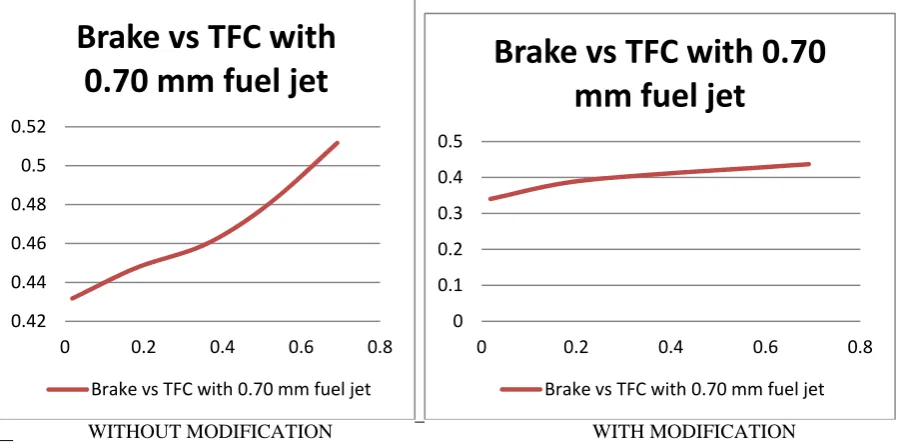
WITHOUT MODIFICATION WITH MODIFICATION
Figure 8: TFC vs Brake Power for jet ( 0.70mm) with and without modification
7. Conclusion
The modification should be planned carefully in such a way that no engine components get affected. This study also concern about the improvement in the fuel economy and brake thermal efficiency. Based on calculation and graphs plotted, an optimum value of fuel and efficiency is taken into consideration. The 0.70 jet gave 32% more leaner mixture than 0.85mm. Due to which brake thermal efficiency was improved 11.06% to 12.95 % in 0.70 mm jet and 6.74% to 8.14% in .85mm jet. @(580rpm, 8kgload).The intake port area is increased by porting ,thereby increasing the mass flow rate by 15%, due to which brake thermal efficiency improved or in other words fuel economy increased .Hence modification must be planned carefully as over modification of the inlet port can end up with a device slower than its stock counterpart. Probably the simplest and best modifications have been made in our project to modify the intake system.
REFRENCES
[1] Shivayogi S.Hiremath,A.M.Lakkangavi. &S.N.Kurbet, “Experimental Studies On Performance of A Two Stroke S.I.Engine Two
Wheeler With Modified Dual Intake Manifold and Throttling Systems For Fuel Economy and Emission Control” , Proceedings of 4th Asian – Pacific International Symposium on Combustion and Energy Utilisation @ Bangkok Thailand on Dec 8 – 11 – 1997,Vol - II
[2] Jefry Bin Dedi Efendi, “ VALVE TIMING STUDY OF A SINGLE CYLINDER MOTORCYCLE ENGINE” Faculty of Mechanical
Engineering ,UNIVERSITI MALAYSIA PAHANG, NOVEMBER 2009
[3] Ganeshan.V (2006, internal combustion Engine ; Tata McGraw-Hill).
[4] Singh.Kripal (2009, automobile engineering; vol-2, standard publication).
0 0.2 0.4 0.6 0.8 1
0 0.2 0.4 0.6 0.8
Brake
Power
vs
TFC
with
0.85mm
fuel
jet
Brake
Power vs
TFC 0 0.2 0.4 0.6 0.8
0 0.2 0.4 0.6 0.8
Brake
Power
vs
TFC
with
0.85mm
fuel
jet
Brake
Power vs
TFC 0.42 0.44 0.46 0.48 0.5 0.52
0 0.2 0.4 0.6 0.8
Brake
vs
TFC
with
0.70
mm
fuel
jet
Brake vs TFC with 0.70 mm fuel jet
0 0.1 0.2 0.3 0.4 0.5
0 0.2 0.4 0.6 0.8
Brake
vs
TFC
with
0.70
mm
fuel
jet
Appendix A
Table1
S. NoWieght Force=(W‐S)*g Torque Speed Time F. C Brake power TFC TFC=TFC*3600 bsfc=TFC/BP Heat supplied th=(BP/HS)*100 F.P. I.P.
(kg) S1 S2 S=S2‐S1 (N) (N‐m) N(rpm) (sec) (cc) (kW) (kg/s) (kg/hr) (kg/kW‐hr) (kW) (in %) (KW)
1 0 0.2 0 ‐0.2 2 0.312 580 39.87 10 0.01894048 0.000180587 0.650112867 34.32399109 7.939142212 0.238570862 1.05 1.06894048
2 2 0.2 0.3 0.1 19 2.964 580 36.87 10 0.17993456 0.000195281 0.703010578 3.907034745 8.585126119 2.095887207 1.05 1.22993456
3 4 0.2 0.4 0.2 38 5.928 580 34.97 10 0.35986912 0.000205891 0.741206749 2.059656435 9.051575636 3.975762171 1.05 1.40986912
4 6 0.2 0.7 0.5 55 8.58 580 32.57 10 0.5208632 0.000221062 0.795824378 1.527895191 9.718563095 5.359467186 1.05 1.5708632
5 8 0.2 0.9 0.7 73 11.388 580 30.56 10 0.69132752 0.000235602 0.848167539 1.226867895 10.35777487 6.674479111 1.05 1.74132752
radius=0.156
1 0 0.2 0 ‐0.2 2 0.312 580 60.04 10 0.01894048 0.00011992 0.431712192 22.79309668 5.272045303 0.359262467 1.2 1.21894048
2 2 0.2 0.3 0.1 19 2.964 580 57.94 10 0.17993456 0.000124266 0.447359337 2.486233535 5.463127373 3.293618247 1.2 1.37993456
3 4 0.2 0.4 0.2 38 5.928 580 56.37 10 0.35986912 0.000127728 0.459819053 1.277739676 5.615284726 6.408742167 1.2 1.55986912
4 6 0.2 0.7 0.5 55 8.58 580 53.91 10 0.5208632 0.000133556 0.480801336 0.923085631 5.871519199 8.871012465 1.2 1.7208632
5 8 0.2 0.9 0.7 73 11.388 580 50.66 10 0.69132752 0.000142124 0.511646269 0.740092437 6.248195815 11.06443429 1.2 1.89132752
Weight on Spring
Reading With 0.85 mm fuel jet
Reading With 0.70 mm fuel jet
0 0.1 0.2 0.3 0.4 0.5 0.6 0.7 0.8 0.9
0 0.2 0.4 0.6 0.8
Brake
Power
vs
TFC
with
0.85mm
fuel
jet
Brake Power vs TFC
0.42 0.44 0.46 0.48 0.5 0.52
0 0.5 1
Brake
vs
TFC
with
0.70
mm
fuel
jet
Table2
S. NoWiegh Force=(W‐S)*g Torque=F*0.156 Speed Time FC Brake power TFC TFC bsfc HS th=(BP/HS)*100 FP IP
(kg) S1 S2 S=S2‐S1 (N) (N‐m) N(rpm) (sec) (cc) (kW) (kg/s) (kg/hr) (kg/kW‐hr) (kW) (in %)
1 0 0.2 0 ‐0.2 2 0.312 580 45.34 10 0.01894048 0.0001588 0.571680635 30.18300672 6.981332157 0.271301803 1.05 1.06894 2 2 0.2 0.3 0.1 19 2.964 580 41.33 10 0.17993456 0.000174208 0.627147351 3.485419091 7.658688604 2.349417365 1.05 1.22993 3 4 0.2 0.4 0.2 38 5.928 580 39.57 10 0.35986912 0.000181956 0.655041698 1.820222025 7.999332828 4.498739179 1.05 1.40987 4 6 0.2 0.7 0.5 55 8.58 580 38.23 10 0.5208632 0.000188334 0.678001569 1.301688369 8.279717499 6.290832991 1.05 1.57086 5 8 0.2 0.9 0.7 73 11.388 580 37.29 10 0.69132752 0.000193081 0.695092518 1.005446041 8.488431215 8.144349674 1.05 1.74133
radius=0.156
1 0 0.2 0 ‐0.2 2 0.312 580 76.17 10 0.01894048 9.45254E‐05 0.340291453 17.96635847 4.155620323 0.455779848 0.7 0.71894 2 2 0.2 0.3 0.1 19 2.964 580 67.2 10 0.17993456 0.000107143 0.385714286 2.143636474 4.710321429 3.820005975 0.7 0.87993 3 4 0.2 0.4 0.2 38 5.928 580 63.5 10 0.35986912 0.000113386 0.408188976 1.134270638 4.984781102 7.21935653 0.7 1.05987 4 6 0.2 0.7 0.5 55 8.58 580 61.4 10 0.5208632 0.000117264 0.422149837 0.810481211 5.155270358 10.10350891 0.7 1.22086 5 8 0.2 0.9 0.7 73 11.388 580 59.3 10 0.69132752 0.000121417 0.437099494 0.632261094 5.337834739 12.95145979 0.7 1.39133
Weight on Spring
Reading With 0.85 mm fuel jet (after modification)
Reading With 0.70 mm fuel jet (after modification)
0 0.1 0.2 0.3 0.4 0.5 0.6 0.7 0.8
0 0 2 0 4 0 6 0 8
Brake
Power
vs
TFC
with
0.85mm
fuel
jet
Brake Power vs TFC
0 0.1 0.2 0.3 0.4 0.5
0 0.2 0.4 0.6 0.8