Experimental and Finite Element
Analysis of Base Frame for Rigidity
Amit V. Chavan
Pg Student, Mechanical Engineering Department, R.I.T, Sakharale, Maharashtra, India
S.S Gawade
Associate Professor, Mechanical Engineering Department, R.I.T, Sakharale, Maharashtra, India,
Abstract:
In this paper Experimental and Finite Element Analysis of Base Frame for Rigidity is presented. The assurance of rigidity as per API 610 is mandatory for pumps base frame supplied in petrochemical industry. A proven rigidity test procedure is used for testing the structural stiffness of base frame in line with API 610 clause 6.3.5. For typical base frame, the stiffness is measured by means of rigidity test (actual measurement) for different load cases. The test is carried out to check the conformance of the existing design to API 610 stiffness requirement. Since the existing design fails to meet this requirement, few potential design modifications are suggested. These modified cases are simulated using FEA techniques for stiffness qualification. ANSYS is used for simulation of these cases including that of existing design, for bench marking and comparison purpose. The results of FE analysis are presented in terms of deflection at coupling side shaft end (guideline form API 610), which is supported between bearings in pump bearing housing at static condition. Based on these results, best feasible design solution is proposed and validated experimentally.
Keywords: API 610, Centrifugal Pump, FEM Analysis, nozzle load, Rigidity, Stiffness Test.
1. Introduction
Pumps are widely used in various industries like petrochemical, textile, chemical, based on application. However, for petrochemical industry compliance of API 610 is mandatory. Generally, the piping systems carrying gases, liquids etc. is subjected to excessive piping reactions in pumps, thus causing higher vibrations, coupling failures, and pump shaft misalignments. In severe cases there are flanged joint leaks and the occasional occurrence of impeller rub or casing distortion. Excessive shaft misalignment in turn leads to premature seal and bearing failures. These difficulties are a costly maintenance item that can also result in plant shutdowns, and in severe cases, fires and extensive damage. Recognizing the critical importance of managing piping loads on rotating equipment, engineers have established standards for allowable forces and moments for rotating machinery. These standards become design criteria for the equipment manufacturer and establish allowable limits for the piping system designer. The American Petroleum Institute standard for centrifugal pumps provides a table for the maximum allowable forces and moments for various flange sizes. The standard stipulates that pressure casings are to be designed to twice the maximum allowable values, and limits the allowable coupling-end shaft displacement under specified test conditions as per API 610 standard (Table 12).
validation. This paper describes how the centrifugal pump base frame stiffness can be improved by using FEA technique.
2. API 610 Stiffness Test Acceptance Criteria
Table 1. Stiffness Test Acceptance Criteria
The stiffness test acceptance criteria for rigidity testing are given in Table 1. API 610 Consider only two loads cases, Myc and Mzc. In Myc loading condition, loads are applied on suction or discharge nozzle, to create moment about Y axis and deflection of shaft is in Z direction. In Mzc loading condition loads are applied on suction or discharge nozzle, to create moment about Z axis and deflection of shaft is in Y direction. There is no effect of Mxc loading condition on shaft deflection; hence API 610 doesn’t consider this loading effect. However, in present paper, the above equations are described in terms of subscript ‘s’ for suction and subscript ‘d’ for discharge.
3. Experimental Setup
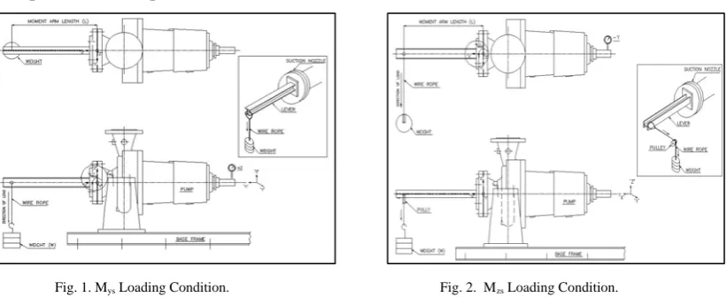
Fig. 1. Mys Loading Condition. Fig. 2. Mzs Loading Condition.
Typical OH2 pump base frame of interest is considered for rigidity analysis. Centrifugal pump consists of the shaft which is supported by two bearings. One end of the shaft is connected to the coupling and the other end of the shaft is connected to the impeller which is in overhung position. Bearing housing consist of bearing through which shaft is fitted. This entire pump assembly is mounted on base frame pedestal. The pump assembly is fixed on base frame pedestal by using bolts, while the base frame is fixed on rails, through foundation bolts. A lever made out of an “I” beam is welded to the flange which is bolted to suction nozzle of pump. At the other end of lever, weights are attached by using wire ropes. To measure the coupling end shaft deflection of pump, a dial indicator is used which is mounted on an independent dial stand. In turn, the dial stand is fixed to the floor. The stiffness test is carried out at pump static condition. For stiffness test purpose four load cases considered are Mys Mzs,Myd,Mzd., out of that only Mys ,Mzs load cases are illustrated in Fig. 1 and Fig. 2.Experimental set up of Myd load case is similar to that of Mys load case, except lever is attached to the delivery nozzle of pump. Experimental setup Mzs Loading Condition is shown in Fig. 2. A pulley is fixed on separate stand to hang the weights using wire ropes. Experimental set up of Mzd load case is similar to that of Mzs load case, except the lever is attached to the delivery nozzle of pump. In stiffness testing depending on pump suction and discharge nozzle diameters, nozzle load values have been taken from API 610 (Table 4).In Existing design the coupling end shaft deflections found to be not in conformance with API 610 stiffness requirement. For the purpose of comparison and validate the experimental results, it was thought to cross verify against FE technique using ANSYS software.
Base plate intended for grouting Loading
condition
Pump shaft displacement
µm (in) Direction
Myc 175 (0.007) +Z
Mzc 75(0.003) -Y
Myc and Mzc equal the sum of the allowable suction and discharge nozzle moments from table 4.
4. FEA of Base Frame
FE analysis of base frame is carried out in order to investigate low stiff area of pump base frame.
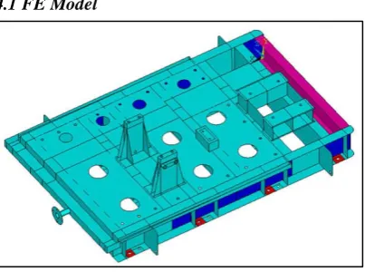
4.1 FE Model
Fig. 3. ANSYS Model of Existing Base Frame Design.
In FEA optimum care must be taken in selection of proper element for analyzing the problem. For analysis SHELL63 element was used to model the base frame. BEAM4 element is used to model the lever. MASS21 element was used for Pump Casing. Pedestal mounting blocks are created by SLOSH190 element. The model is meshed using ANSYS 10.0 confirming that mesh is dense enough, so that results with required accuracy should be obtained and also it should be course enough such that the number of nodes and element should not be too large to solve for a computer used. The numbers of element generated are 119893 and the numbers of nodes are 119415. The meshed model along with loads and boundary condition are discussed section 4.3. Units of analysis were kg and µm.
4.2 Material Properties
Material grade used for pump base frame is IS 2062 Gr.Fe 410B. The Material properties are as listed in Table2
Table 2. Material Properties
4.3 Boundary Conditions
Fig. 4. Boundary Conditions for Mys Load case. Fig. 5. Boundary Conditions for Mzs Load case.
Applying boundary conditions is the most important step in the Finite Element Analysis. Meshing and boundary condition for Mys and Mzs load case is shown in Fig. 4 and Fig. 5. Eight foundation bolts are fixed in all direction (i.e. x, y, and z) as shown in Fig. 4 and Fig. 5. The beam element is used to transfer forces to mass
Density Young’s Modulus Poisson’s Ratio
Ultimate Tensile
Strength Yield Strength
element. Mass element is connected to base frame pedestal using rigid elements. The resistance offered by structure is in terms of beam deflection.
5. Results and Discussions
5.1. Existing Design-Deflection Comparison
Experimental Vs FEA
Fig. 6. Shaft Deflection for Mys andMyd Condition. Fig. 7. Shaft Deflection for Mzs and Mzd Condition.
Experimental and FEA results of Existing design are shown in Fig. 6 and Fig. 7. From above graphs, it can be observed that the existing design is not meeting the stiffness requirements of API 610 (Higher than Maximum Limiting Values). After Analyzing Structural behavior of base frame, it is observed that effective increase in stiffness can be achieved by base frame redesigning. It is clear that base frame stiffness needs to be increased in X-Z plane. However, from the stress plot shown in Fig. 11, it was observed that the induced stress is low for existing design and there is good scope for design optimization.
5.2 Modified Design - Cases
The rigidity of base frame can be improved by any or combination of the following points • Increasing number of stiffeners below Pedestal.
• Increasing number of slant ribs
• Changing “C” section to box-section of cross channels below Pedestal.
Accordingly, the potential design cases have been explored to ensure the design in accordance with API requirement. As a part of design optimization, lower channel sizes are considered while exploring the modified design cases. The descriptions of modified design cases are listed in Table 3.
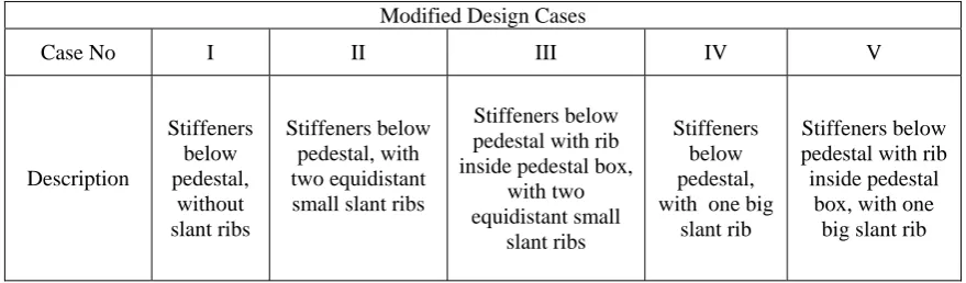
Table 3. Modified Design Cases
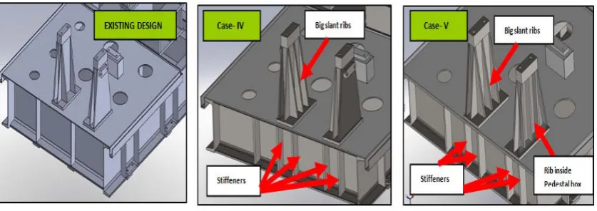
For above cases FE analysis has been carried out. From comparison of FE results of above cases, it is observed that the deflections for all the cases are significantly reduced with the best, in the Cases-IV and V. Hence only these cases have been presented in Fig. 8.However, Case-V is not feasible from Pedestal cooling perspective, as the rib inside pedestal box restricts the water circulation. Henceforth, Modified Design Case-IV, which looks to be the best practical solution, has been considered for test validation.
Modified Design Cases
Case No I II III IV V
Description Stiffeners below pedestal, without slant ribs Stiffeners below pedestal, with two equidistant small slant ribs
Stiffeners below pedestal with rib inside pedestal box,
with two equidistant small slant ribs Stiffeners below pedestal, with one big
slant rib
Stiffeners below pedestal with rib inside pedestal
box, with one big slant rib
Fig. 8. Existing Design Vs Modified Design Cases.
5.3 Modified Design-Deflection Comparison
Following graphs show the deflection comparison between Experimental and FE results of modified design.
Experimental Vs FEA
Fig. 9. Shaft Deflection for Mys andMyd Condition. Fig. 10. Shaft Deflection for Mzs and Mzd Condition
Deflection results of Modified design are within acceptble limits of API 610 stiffness criteria. The stress plots for both the designs are presented in Fig. 11 and Fig. 12.
Fig. 11. Existing Design:σvm - 8.63 kg/mm2 Fig. 12. Modified Design:σvm - 6.75 kg/mm2
The von misses stress (σvm) observed is maximum in existing design among all, for Myd load case. It is 8.63 kg/mm2 and shown in Fig. 11, where as for modified design it is 6.74 kg/mm2 as shown in Fig. 12.In Modified design it is well below Yield point of Material; hence it is concluded that the design is safe and suitable for manufacturing.
6. Conclusions:
1) The Modified Design (Case-IV) is considered as the best design case which meets API 610 stiffness test criteria; it can be implemented for next fleet of pumps.2) The smaller slant ribs have no significant effect on stiffness.3) Since the bigger slant ribs have reasonably good effect on improving stiffness, the rigidity can be increased with more numbers of ribs. However, it has space implications. 4) In Modified Base Frame Design, the Von-mises Stress Levels are well below yield point, thus the design is safe with respect to load applied 5) A weight reduction of 8.3 % of raw material cost is observed in present design improvement of base frame.
7. Acknowledgments
The authors like to express their thanks to the department of Mechanical Engineering of R.I.T. Sakharale, Maharashtra, India for their encouragement and support during this work.
References:
[1] API standard 610, 2004, “Centrifugal Pumps for Petroleum, Petrochemical and Natural Gas Industries,” 10th edition, American
Petroleum Institute, Washington D.C
[2] A.J. Stepanoff, 1953, “Centrifugal and Axial flow pumps - Theory, Design & Application,” John Wiley and Sons, 2nd edition
[3] Fu-Zhen Xuan, Shan-Tung, February-2003, “Bulging Deformation of Ethylene Compressor Base Box,” Engineering Failure Analysis.
[4] N.K.Mehta, 1996, “Machine Tool Design and Numerical Control,” Tata McGraw-Hill Publishing Company, New Delhi, 2nd edition
[5] S.Ramamrutham and R.Narayanan, 1967, “Strength of materials,” Dhanpat Rai publishing company (P) Ltd ,13th edition.
[6] T.R.Chandrupatla and A.D. Belegundu, 2004, “Introduction to Finite Elements in Engineering,” Prentice Hall of India, 3rd edition.