Enhancement of Voltage Stability in Fixed
Speed Wind Energy Conversion Systems
using FACTS Controller
K.MALARVIZHI1*, K.BASKARAN2
1*Department of Electrical and Electronics Engineering,
Kumaraguru College of Technology, Coimbatore,Tamilnadu,India.
Mobile No: +91-98658 52223
2Department of Computer Science Engineering.
Government College of Technology, Coimbatore, Tamilnadu,India.
ABSTRACT
Grid connected Fixed Speed Wind Turbines (FSWT) may cause voltage stability problems which results in islanding of the generator from the grid. Voltage stability is a major issue to achieve the uninterrupted operation of wind farms equipped with FSWTs. In this paper the design of a Static Synchronous Compensator (STATCOM) based on Cascaded H-Bridge (CHB) – Multi Level Converter (MLC) is proposed. The dynamic behavior of 3 level and 5 level CMC based STATCOM is validated by simulation with MATLAB/SIMULINK simulation techniques. A detailed analysis of the operating characteristics of the various inverter topologies are compared in the paper. To analyze the performance of the STATCOM connected in shunt with the transmission line, an induction generator based wind farm has been considered. The complete digital simulation of the STATCOM incorporated into the power system is performed in the MATLAB/SIMULINK environment and the results are presented to validate the feasibility of the proposed topology.
KEYWORDS
Wind Farm, Induction Generator, Point of Common Coupling (PCC), Voltage Source Converter (VSC), Flexible AC Transmission Systems (FACTS), Pulse Width Modulated (PWM) inverter.
I INTRODUCTION
Wind power very often is a source of voltage fluctuating and flicker. The dominating type of wind generators are induction generators, since they are robust and cost effective. But they do not contribute to voltage regulation because they are substantial absorbers of reactive power. Voltage control problems are remedied by installation of fixed and Mechanically Switched Capacitors (MSC). Regular voltage flicker and voltage fluctuations caused by varying output wind generators cannot be solved using conventional methods [1].
voltage support capability with its nature of voltage source [3].The dynamic simulations are used to verify the performance of the proposed STATCOM control strategy using MATLAB/SIMULINK software tool.
2. POWER FLOW CONTROL IN TRANSMISSION LINES
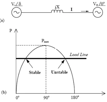
Active and reactive power in a transmission line depend on the voltage magnitudes and phase angles at the sending and receiving ends as well as line impedance. To facilitate the understanding of the basic issues in power flow control using VSC-based FACTS controllers, the simple model shown in Fig 1(a) is used. The sending and receiving ends are connected by an equivalent reactance X, assuming that the resistance of high voltage transmission lines is very small. The receiving end is modeled as an infinite bus with a fixed angle of 0°.
Fig 1 (a) Equivalent Circuit Model (b) Power Angle Curve of a Lossless Line
For the receiving end side;
SR = PR+ j QR (1)
PR = VSVR sin (2)
X QR = VSVR(cos -VR) (3)
X
Similarly, for the sending end Ps = VSVR sin
X
= Pmax sinδ (4)
Qs = VS (VS-VR cos δ) (5)
X
The equations for sending and receiving end active power flows, PS and PR, are equal because the system is
For an angle above 90°, increased demand results in less power transfer, which accelerates the generator, and further increases the angle, making the system unstable; on the left side intersection, however, the increased angle increases the electric power to match the increased mechanical power. In determining an appropriate margin for the load angle, the concepts of dynamic or small signal stability and transient or large signal stability are often used. Typical power transfers correspond to power angles below 30°; to ensure steady state rotor angle stability, the angles across the transmission system are usually kept below 45°.
Eq (2) and Eq(4) shows that the real or active power transfer depends mainly on the power angle and inspection of Eq (3) and Eq(5) shows that the reactive power requirements of the sending and receiving ends are excessive at high angles and high power transfers. It is also possible to conclude that reactive power transfer depends mainly on voltage magnitudes, which flows from the highest voltage to the lowest voltage, while the direction of active power flows depends on the sign of the power angle.
Eq (2) to Eq (5) show that the power flow in the transmission line depends on the transmission line reactance, the magnitudes of sending and receiving end voltages and the phase angle between the voltages. The concepts behind FACTS controllers are to enable control of these parameters in real-time and, thus, vary the transmitted power according to system conditions. The ability to control power rapidly, within appropriately defined boundaries, can increase transient and dynamic stability, as well as the damping of the system. For a given power flow, a change of X also changes the angle between the two ends. Regulating the magnitudes of sending and receiving ends voltages, VS and VR can also control power flow in a transmission line. However, these values are
subject to tight control due to load requirements that limit the voltage variations to a range between 0.95 and 1.05 p.u., and hence cannot influence the power flows in a desired range.
Hence, the regulation of voltage magnitude has much more influence over the reactive power flow than the active power flow. Of the FACTS controllers, the STATCOM has the ability to increase/decrease the terminal voltage magnitude and, consequently, to increase/decrease power flows in the transmission line [4]. FACTS controllers can be used to control steady state active and reactive power flow, but it should be also noted that these fast controllers could have pronounced, positive impact on transient and dynamic conditions in a power system if designed properly. The STATCOM has the ability to control reactive power absorption/generation, and since its time response is very fast, sometimes even less than one cycle, it can be used to effectively prevent the problem of voltage stability in FSWTs.
3. WIND TURBINE MODEL
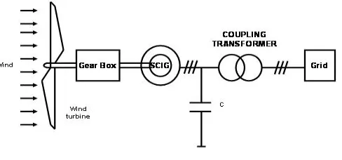
The dynamic stability of induction generators directly connected to a grid as shown in Fig 2 depends on the characteristic of the generator, the grid configuration and the characteristic of the disturbance.
Fig 2 Grid connected FSWT
voltage control because of its rapid and continuous response characteristics. Therefore, it is more suitable for voltage flicker mitigation at the connection point of the wind farm [7].
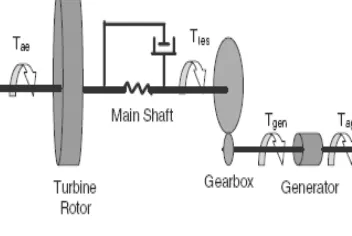
In order to evaluate the improvement of the stability conditions that a STATCOM can produce in the system with a wind farm connected to a weak grid, power system simulation have been performed in MATLAB/ SIMULINK. A sketch of the power system that has been studied is outlined as drive train model as shown in Fig 3.
Fig 3 Drive Train Model
In this model it is known that a wind turbine with squirrel-cage induction generator has a relatively soft coupling between the turbine rotor and the induction generator rotor this means that a two mass representation of the shaft would be recommended. One mass is representing the turbine and another representing the generator rotor. In case of non-representation of the shaft by two-mass model, that is, the shaft is represented by a lumped-mass model, the result would give an oversimplified representation of the wind turbine shaft system, but the behavior of the frequency deviation follows the expected average frequency curve. Considering that the study will compare cases with or without the STATCOM a simpler representation of the shaft has been used in the study, which means, a single mass representation.
4. STATCOM TOPOLOGY
The STATCOM is based on a solid – state voltage source implemented with an inverter and connected in parallel to the power system through a coupling reactor [12]. A STATCOM consists of an inverter and a DC capacitor as shown in Fig 4. With this arrangement, this device can supply both leading and lagging vars with a small energy storage device.
Fig 4 STATCOM Inverter
real power from the AC system if the converter output voltage is made to lag the AC system voltage. The amount of exchanged real power is typically small in steady state; hence, the firing angle is also small. The real power that is being exchanged by the transmission system must be supplied or absorbed at its DC terminals by the DC energy storage. In contrast, the reactive power exchange is internally generated or absorbed by the voltage-sourced converter, without the DC energy storage device playing any part in it.
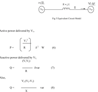
If two sources V1 with a phase angle of δ and V2 with a phase angle of 0 are connected together by means
of an inductive link of impedance (R +j X) ohms as shown in Fig 6 and if the active power flowing into the source V2 is constrained to be zero (because this represents the STATCOM situation) the power delivered by the source V1
(which will not be zero and it will be equal to the power absorbed by the resistance in the link) and the reactive power delivered to the link by the source V2 will be given by the following relations (Assuming is small and R <<
X ).
Fig 5 Equivalent Circuit Model
Active power delivered by V1,
V12
P = R 2 W (6)
Reactive power delivered by V2,
(V1V2)
Q = var (7) R
Also,
V2 (V2-V1)
Q = var (8) X
Where the powers are for one phase and voltages have phase values. These relations can be used up to about 20 degrees for .Active Power drawn from the source V1 is independent of sign of phase angle (only V1 can supply
losses in R because of the zero active power constraint at V2) whereas the reactive power delivered by V2 is directly
proportional to the phase angle. In the STATCOM context, the source V1 is the power system voltage at the bus
where the STATCOM is connected, V2 is the AC voltage generated by the inverter in the STATCOM, R is the total
loss resistance in the link comprising the winding losses in the link inductor, interface magnetic, the inverter switches and snubber etc. It is also possible to derive the following useful relationships in this context. The phase angle of V1 with respect to V2,
R (V2-V1)
= (9)
This shows that the relative phase angle is linearly related to the voltage magnitude difference (for small differences) and hence the reactive power delivered by V2 is proportional to the voltage magnitude difference. Thus Q is
proportional to δ or equivalently to (V2-V1). In the STATCOM, the required AC voltage source V2 is generated by
inverting the DC voltage, which is assumed available across the capacitor in the DC side. But if the active power which goes into the inverter from the mains is kept zero, the initially charged capacitor will soon discharge down to zero due to active power losses in the inverter which the D.C. side will have to supply. The DC side voltage will remain constant (or at least controlled) if the power drawn from mains is just enough to supply all the losses which take place everywhere due to the flow of demanded reactive current. The DC side capacitor voltage is,
V1 X
Vdc = 1- (10)
k R
where V1 is the rms phase voltage of AC mains, k is a constant, which also absorbs the modulation index of PWM
process in the Inverter.VSC transforms, through appropriate switching sequence, DC voltage at its DC terminals into an AC voltage of controllable frequency, magnitude and phase angle at its terminals. The output voltage could be fixed or variable, at a fixed or variable frequency. For FACTS application purposes, it is always assumed that the output voltage waveform has a fixed frequency equal to the fundamental frequency of a power system to which the converter is connected, as high voltage and power harmonics could create many problems.
5. STATCOM CONTROL STRATEGY
Fig.6shows the block diagram of phase angle control scheme implemented in STATCOM. A STATCOM is configured to keep the reactive power delivered by the source at a zero value as long as the reactive demand is within the STATCOM rating [9].
The control of STATCOM reactive power is by pure α control. The source side voltages and currents are sensed and the reactive power is calculated by analog/pulse circuitry. This calculated value is compared with the desired value (usually zero) and the error is processed in a Proportional-Integral Controller [10]. The error output decides the phase shift needed in the inverter output in order to develop the required DC bus voltage such that the inverter output voltage magnitude will be sufficient to make the Inverter deliver the var required by the load. The inverter is gated by a fixed PWM pattern optimized for eliminating chosen harmonics (usually fifth, seventh, eleventh etc; triple harmonics need not be eliminated since they do not result in current flows in a three wire system).
The PWM technique is commonly employed to generate high quality output waveforms by relatively low power converter used in wind power applications[13]. With this technique, the output of each converter pole is switched several times during a fundamental cycle between the positive and negative terminals of the DC source.PWM requires a considerable increase in the number of switch operations ,thereby it generally increases the switching losses of the converter. However, the always increasing switching frequency of modern solid-state power switches used in FACTS controllers made possible the use of PWM in high power applications .
The aim of the PWM control scheme is to maintain constant voltage magnitude at the point of common coupling, under system disturbances. The control system only measures the rms voltages at the PCC, i.e., no reactive power measurements are required. With these converters, the ac output voltage can be controlled, by varying the width of the voltage pulses.
6. TEST SYSTEM AND COMMENTS ON RESULTS
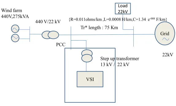
In order to evaluate the improvement of the stability conditions that a STATCOM can produce in the system with a wind farm connected to a weak grid, power system simulation is performed in MATLAB/ SIMULINK as shown in Fig 7.A 220 KW wind farm consisting of single Squirrel Cage Induction Generator (SCIG) driven by Fixed Speed Wind Turbine (FSWT) is connected to a power grid through a step-up transformer T1 and a
power line. The Wind Turbine Generator (WTG) with a rated power capacity of 220kW is considered here. A STATCOM is shunt connected at the 22kV bus (the high voltage terminal of the transformer T1) to provide dynamic
reactive compensation.
To reduce the size of the STATCOM, a fixed capacitor bank is used to supply about 10 Mvar reactive power at the nominal voltage condition. The parameters of the system components are as follows. SCIG: rated power = 220 kW, rated stator voltage = 440 V, stator resistance = 0.0079 pu, rotor resistance = 0.025 pu, stator leakage inductance = 0.07939 pu, rotor leakage inductance = 0.4 pu, magnetizing inductance =4.4 pu; Transformer T1: turns ratio = 440 V/22 kV, equivalent leakage reactance = 0.06 pu; Transformer T2: turns ratio = 22 kV/13 kV.
VSI
Step up transformer 13 kV / 22 kV 440 V/22 kV
Tr* length : 75 Km Wind farm
440V,275kVA
Grid
PCC
{R=0.011ohms/km ,L=0.0008 H/km,C=1.34 e-008F/km}
22kV Load
22kV
Fig 7 Single Line Diagram of the Test System
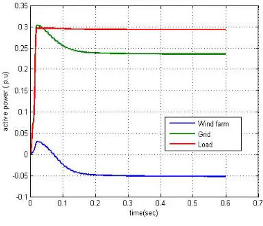
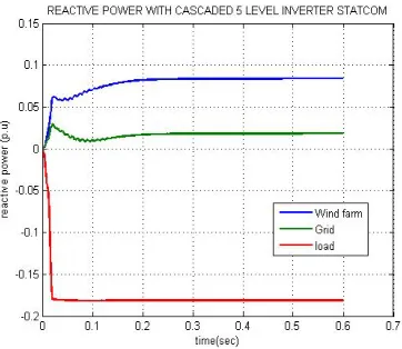
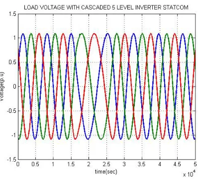
Active power without STATCOM implementation is compared with the active power with conventional STATCOM and 5 level STATCOM.Similarly reactive power and voltage power are compared.
Fig8 Active power without STATCOM
Fig 9 Active power with 3 level inverter STATCOM
Fig11 Reactive power without STATCOM
Fig 12 Reactive power with 3 level inverter STATCOM
Fig14 Load voltage without STATCOM
Fig 15 Load voltage with 3 level inverter STATCOM
7. CONCLUSIONS
This paper has analyzed the transient stability limits of a wind farm with squirrel-cage induction generators. It has been analyzed that the squirrel-cage induction generators used in constant-speed turbines can lead to voltage and rotor instability. The study has demonstrated that an additional active voltage / Var support produced by a STATCOM can significantly improve the recovery of wind turbines from voltage collapse since this device can make a faster restoration of the voltage, improving the stability limit conditions of the induction generators. It is found in the simulation results that the STATCOM can provide a major increase in the transient stability margin of power systems that integrate wind generation. The experimental results provide a clear qualitative verification of transient margin increase in the wind energy conversion system with STATCOM when compared to the system without the STATCOM support. The STATCOM is an optimum candidate for providing ride through in wind farms equipped with asynchronous generators directly connected to the grid. Voltage fluctuations during normal operations can be mitigated and voltage instability during islanding operation can be prevented by using dynamic reactive compensation.
REFERENCES
[1] Pierre Bousseau, Floriane Fesquet, Régine Belhomme, Samuel Nguefeu and Thanh Chau Thai, 2006, “Solutions for the Grid
Integration of Wind Farms—a Survey”. WIND ENERGY; 9:13–25.
[2] N.G.Hingorani andL.Gyugyi2000, Understanding FACTS: Concepts and Technology of Flexible AC Transmission Systems”, New
York: IEEE Press, pp. 135-143.
[3] S.Sirisukprasert, A.Q.Huang, andJ.S.Lai, 2003, “Modeling, analysis and con-trol of cascaded- multilevel converter –based
STATCOM,” in Proc .IEEE PES Gen .Meeting, vol.4, pp.2561–2568.
[4] T. Sun, Z. Chen, and F. Blaabjerg, 2004, “Flicker mitigation of grid connected wind turbines using STATCOM,” in Proc. 2nd
International Conference on Power Electronics, Machines and Drives, Mar. 31-Apr. 2, vol. 1, pp. 175-180.
[5] Z. Saad-Saoud, M. L. Lisboa, J. B. Ekanayake, N. Jenkins, and G. Strbac, 1998., “Application of STATCOMs to wind farms,” IEE
Proc – Generation, Transmission and Distribution, vol. 145, no. 5, pp. 511-516,
[6] C. Banos, M. Aten, P. Cartwright, and T. C Green, 2006, “Benefits and control of STATCOM with energy storage in wind power
generation,” in Proc. 8th IEE International Conference on AC and DC Power Transmission,Mar. 28-31, pp. 230-235.
[7] T. Sun, Z. Chen, and F. Blaabjerg, Mar. 31-Apr. 2, 2004, “Flicker mitigation of grid connected wind turbines using STATCOM,” in
Proc. 2nd International Conference on Power Electronics, Machines and Drives, vol. 1, pp. 175-180.
[8] C. Chompoo-inwai, C. Yingvivatanapong, K. Methaprayoon, and W.J. Lee, “Reactive compensation techniques to improve the
ride-through capability of wind turbine during disturbance,” IEEE Tans. Industry Applications, vol. 41, no. 3, pp. 666-672.
[9] Mohan, N.; Undeland, T. 2005.Robbins, W. Power Electronics. 3rd edition. New York: Wiley, pp. 16–30.
[10] P. C. Krause, 1992, Analysis of Electric Machinery, New York: Mc Graw-Hill, pp.133-163.
[11] V. Akhmatov, 2003, “Analysis of dynamic behavior of electric power systems with large amount of wind power,” Ph.D. thesis,
Technical University of Denmark, Kgs. Lyngby, Denmark.
[12] C. Chompoo-inwai, C. Yingvivatanapong, K. Methaprayoon, and W.-J. Lee,2005, “Reactive compensation techniques to improve the
ride-through capability of wind turbine during disturbance,” IEEE Tans. Industry Applications, vol. 41, no. 3, pp. 666-672.
[13] K.C. Divya, P.S. Nagendra Rao,,2004, “Study of dynamic behaviour of grid connected induction generator,” IEEE Power
Engineering Society General Meeting, vol.2, pp. 2200-2205.
AUTHORS
K.Malarvizhi received her Bachelor of Engineering degree in Electrical and Electronics Engineering from Bharathiar University, India in 1993, Master of Engineering degree in Electrical and Electronics Engineering from Anna University, Chennai, India in 2006.She is currently a Research Scholar in the department of Electrical and Electronics Engineering, Anna University, Coimbatore ,India. She is a member of ISTE, and member of SSI. She is working as an Assistant Professor in the department of Electrical and Electronics Engineering, Kumaraguru College of Technology, Coimbatore, India. Her areas of interest are Electrical Machines, Power Electronics, Power Systems, Renewable Energy Generation and its Applications.